

Page 1
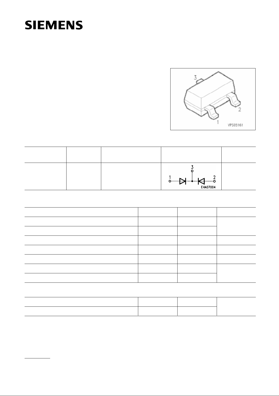
Silicon Switching Diode Array SMBD 6100
● For high-speed switching applications
● Common cathode
Type Ordering Code
Marking
Pin Configuration
Package
(tape and reel)
SMBD 6100 Q68000-A8438s5B SOT-23
Maximum Ratings
Parameter Symbol Values Unit
Reverse voltage V
R 70 V
Peak reverse voltage VRM 70
Forward current IF 200 mA
Surge forward current, t= 1
Total power dissipation, T
µs IFS 4.5 A
S =35˚C Ptot 250 mW
Junction temperature Tj 150 ˚C
Storage temperature range T
stg – 65 … + 150
1)
Thermal Resistance
Junction - ambient
2)
Rth JA ≤ 600 K/W
Junction - soldering point Rth JS ≤ 460
1)
For detailed information see chapter Package Outlines.
2)
Package mounted on epoxy pcb 40 mm × 40 mm × 1.5 mm/6 cm2 Cu.
Semiconductor Group 1
5.91
Page 2
Electrical Characteristics
I
I
I
I
A = 25 ˚C, unless otherwise specified.
at T
SMBD 6100
Parameter Symbol
DC characteristics
V
(BR) 70 – –
(BR) = 100 µA
F
V
F = 1mA
F = 100 mA
I
R – – 100
VR = 50 V
AC characteristics
C
D – – 2.5
R = 0, f = 1 MHz
V
rr ––15
t
F = 10 mA, IR = 10 mA, RL = 100 Ω
measured at I
R = 1 mA
min. typ. max.
550
850
–
–
700
1100
UnitValues
VBreakdown voltage
mVForward voltage
nAReverse current
pFDiode capacitance
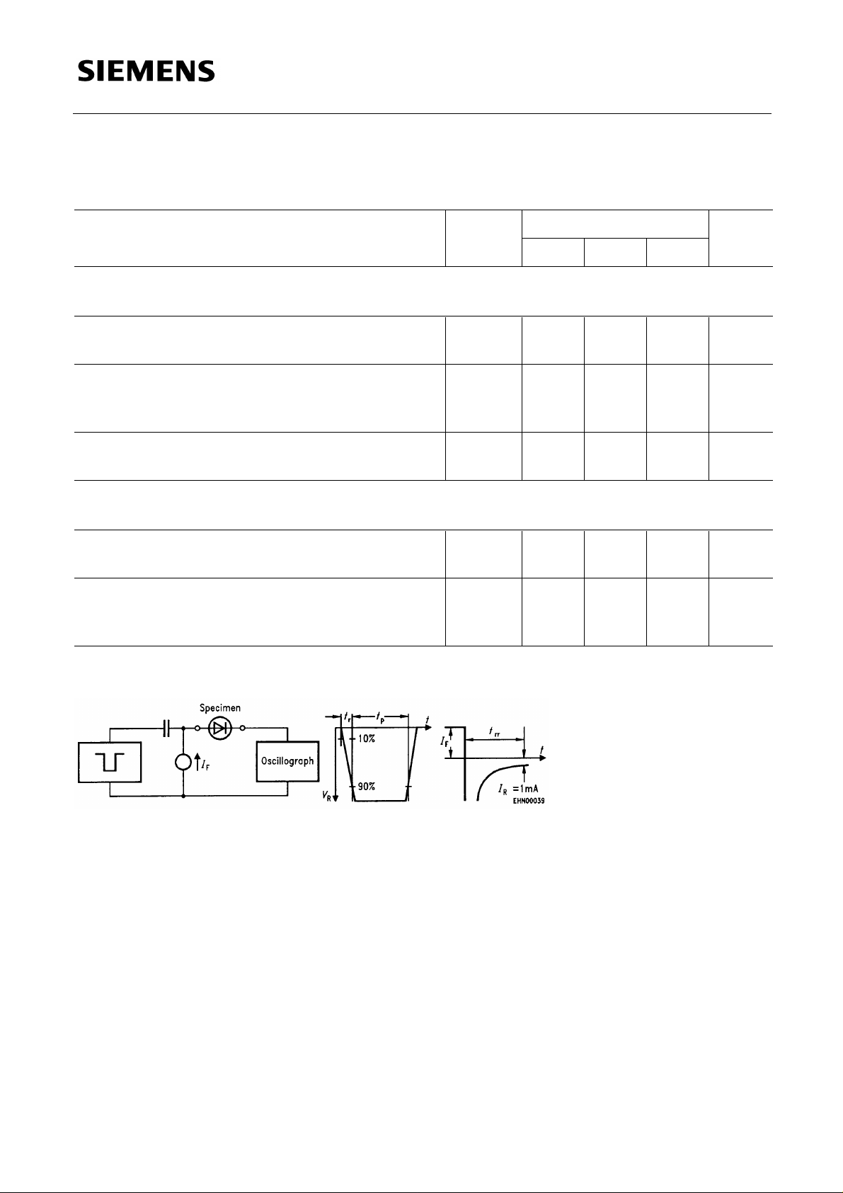
nsReverse recovery time
Test circuit for reverse recovery time
Pulse generator: t
p = 100 ns, D = 0.05 Oscillograph: R = 50 Ω
r = 0.6 ns, Rj = 50 Ω tr = 0.35 ns
t
≤ 1pF
C
Semiconductor Group 2
Page 3

SMBD 6100
Forward current IF = f (TA*; TS)
* Package mounted on epoxy
Reverse current IR = f (TA)
Forward current I
A = 25 ˚C
T
F = f (VF)
Peak forward current I
A = 25 ˚C
T
FM = f (t)
Semiconductor Group 3
Page 4

Forward voltage VF = f (TA)
SMBD 6100
Semiconductor Group 4
 Loading...