

Page 1
−∆
SM6780AS
NIPPON PRECISION CIRCUITS INC.
Ni-Cd/Ni-MH Battery Charger IC
OVERVIEW
The SM6780AS is a quick charge control IC for Nickel-Cadmium (Ni-Cd) and Nickel Metal Hydride (Ni-MH)
rechargeable batteries. It supports quick charge, supplemental and pulse trickle charging modes. The charging
mode is selected automatically in response to the battery voltage, temperature and charging time.
The quick charge uses either negative delta voltage detection ( −∆ V), temperature detection ( ∆ T/ ∆ t), or charging time cutoff to control the charging process. In addition, the quick charge mode can be placed on hold, if the
battery voltage or battery temperature are abnormal, until normal conditions are restored.
The SM6780AS requires few external components to realize a high-stability quick charge battery charger.
FEATURES
■
Ni-Cd/Ni-MH battery quick charge control
■
V, ∆ T/ ∆ t, and maximum charge time cutoffs
■
3 charge modes (quick charge, supplemental,
pulse trickle charge)
■
3 selectable charge times (80, 120, and 240 minutes)
■
Charge condition LED indicator output (on,
pulsed, off)
■
Low power dissipation mode
■
4.0 to 5.5V operating supply voltage
■
300sec (typ) −∆ V detection invalid time
■
8mV (typ) −∆ V detection accuracy
■
25mV/min (typ) ∆ T/ ∆ t detection accuracy
■
8-pin SOP package
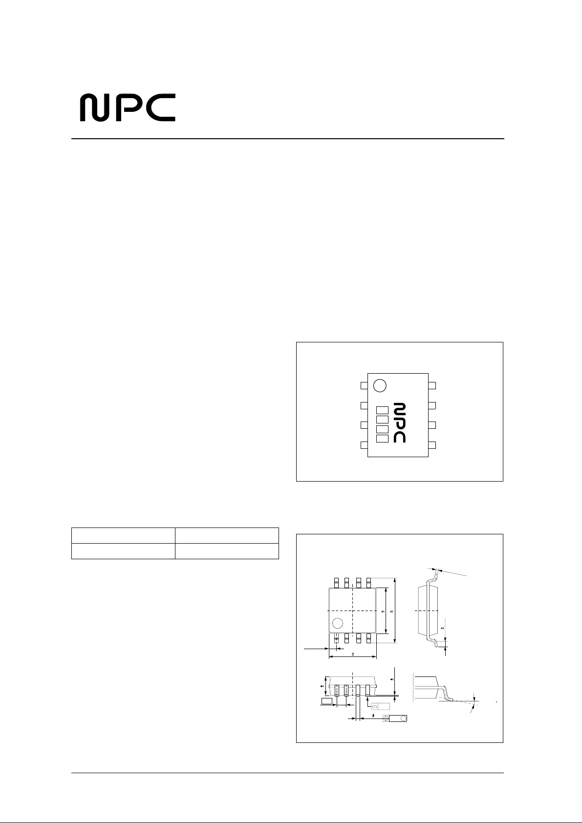
PINOUT
(Top view)
TIME CHGN
LEDN
BATT
VSS
6780AS
INH
VDD
TEMP
ORDERING INFORMATION
Device Package
SM6780AS 8-pin SOP
PACKAGE DIMENSIONS
(Unit: mm)
4.4 0.2
6.2 0.3
0.695typ
1.5 0.1
1.27
5.2 0.3
0.05 0.05
0.10
0.4 0.1
M
0.12
NIPPON PRECISION CIRCUITS—1
0.15
− 0.05
0.4 0.2
+
0.1
0 to 10
Page 2
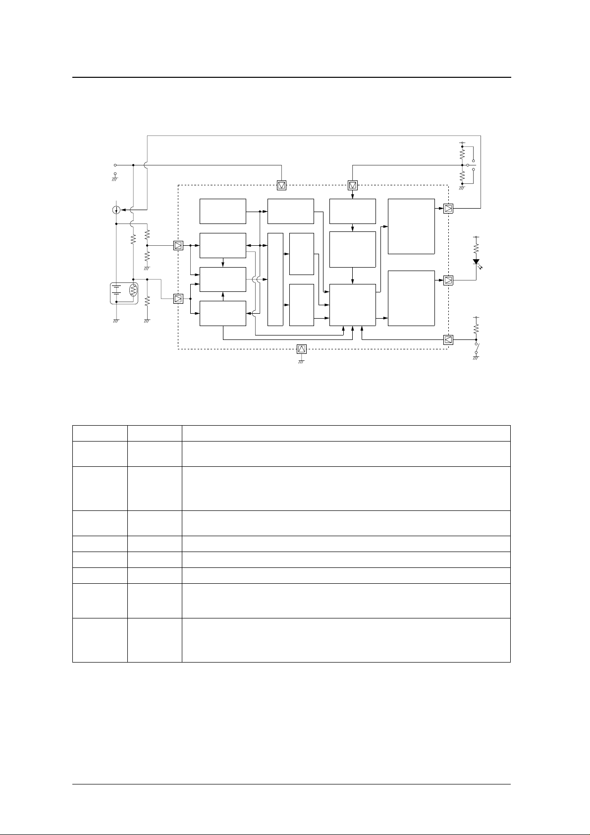
BLOCK DIAGRAM
DC
Input
SM6780AS
VDD
TIMEVDD
Current
Source
Battery
Pack
NTC
BATT
TEMP
Reference
Regulators
Maximum
Cell-voltage Check
Input Select
Temp Check
A/D
OSC
−∆V
Function
Block
∆V/∆t
Function
Block
VSS
PIN DESCRIPTION
Number Name Description
1 TIME
2 LEDN
3BATT
4 VSS Ground
5 TEMP Battery temperature thermistor sensor voltage input
6 VDD Supply
7 INH
8 CHGN
Charge time select 3-level input.
HIGH: 240 minutes, MID (V
/2): 120 minutes, LOW: 80 minutes
DD
Charge indicator LED driver output.
Open-drain output. LOW-level output in quick charge mode. 1Hz pulse output when abnormal battery voltage or
temperature is detected during quick charge mode. High impedance output in supplemental and trickle charge
modes.
Battery voltage detector input.
Connect a high-impedance resistor voltage divider between the poles of the battery for v oltage detection.
Charge inhibit input.
Charging is stopped when HIGH. Charging resumes with the same charge parameters in force prior to the stop
when INH goes LOW again.
Charger control output.
Open-drain output. Battery charging current flows when CHGN is high impedance. Charge current stops when
LOW. High-impedance output in quick charge mode, and pulse output in supplemental and trickle charge
modes.
Timer Mode
Selector
Timing Control
Logic
Charge Control
Logic
CHGN
CHG Driver
VDD
LEDN
LED Driver
VDD
INH
NIPPON PRECISION CIRCUITS—2
Page 3
≤
≤
≤
−
−
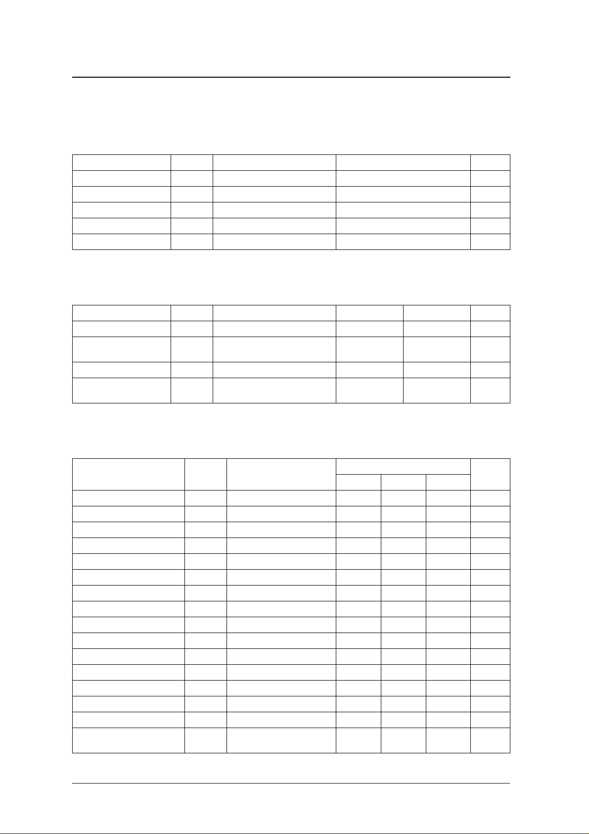
SPECIFICATIONS
Absolute Maximum Ratings
V
= 0V
SS
Parameter Symbol Condition Rating Unit
Supply voltage range V
Input voltage range V
Storage temperature range T
Operating temperature range T
Power dissipation P
DC Characteristics 1
DD
IN
stg
opr
D
−
−
−
−
SM6780AS
0.3 to 7.0 V
0.3 to 7.0 V
55 to 125
0 to 85
150 mW
° C
° C
V
= 4.0 to 5.5V, V
DD
= 0V, Ta = 25 ° C
SS
Parameter Symbol Condition Rating Variation Unit
Maximum temperature voltage V
High-temperature sense
voltage
Low-temperature sense voltage V
Maximum battery voltage V
V
MXT
HTS
LTS
MXV
DC Characteristics 2
V
= 4.0 to 5.5V, V
DD
Parameter Symbol Condition
VDD supply voltage V
BATT input voltage V
TEMP input voltage V
INH HIGH-level input voltage V
INH LOW-level input voltage V
TIME HIGH-level input voltage V
TIME MID-level input voltage V
TIME LOW-level input voltage V
V detection voltage range V
BATT −∆
LEDN output pulse frequency f
BATT standby voltage V
VDD current consumption I
VDD standby current I
LEDN, CHGN sink current I
INH, TIME input leakage current I
LEDN, CHGN output leakage
current
= 0V, Ta = 0 to 85 ° C unless otherwise noted
SS
DD
BATT
TEMP
IH1
IL1
IH2
IM
IL2
DET
LED
STB
DD
STB
OL
L
I
OZ
V
V
TEMP
V
V
HTS
V
> V
TEMP
V
> V
BATT
prohibition
charge cutoff 0.225V
MXT
V
TEMP
LTS
MXV
charge start 0.25V
LTS
charge prohibition 0.4V
charge cutoff or
DD
DD
DD
2.0 ±5% V
±5% V
±5% V
±5% V
Rating
min typ ma x
4.0 5.0 5.5 V
0–V
Disabled when V
< 0.5V 0.5 – V
TEMP
0.7 – – V
– – 0.1 V
V
− 0.5 – – V
DD
(V
/2) − 0.5 – (V
DD
– – 0.5 V
1–2V
–1–Hz
V
1.5 – V
DD
V
= 5V, no load – – 0.5 mA
DD
V
V
V
DD
OL
INH
= 5V, V
= V
= V
= V
BATT
+ 0.8V 10 – – mA
SS
TIME
, no load – – 1 µA
DD
= V
to V
SS
DD
––±1µA
5– –µA
DD
DD
/2) + 0.5 V
DD
0.5 V
DD
Unit
V
V
NIPPON PRECISION CIRCUITS—3
Page 4

FUNCTIONAL DESCRIPTION
Charger Operation
SM6780AS
The SM6780AS battery charger operation starts
when the power is applied or when standby mode is
released. The charging operation is determined by
the BATT and TEMP pin states, and the timer mode
selected.
After charging starts, the battery voltage and temperature are monitored to check that they are within
quick charging rated ranges. If within rated range,
quick charge mode is selected. If outside rated range,
pulse trickle charge mode is selected.
Charging Rate
The charging rate is determined by the external
charger current source. If the quick charge mode
charging rate is considered as unity, then the supplemental charging rate is 1/16, and the pulse trickle
charging rate is 1/256. The charging rate for supple-
286µs
Hi-Z
Low
4576µs
Quick charge uses either negative delta voltage
detection ( −∆ V), temperature detection ( ∆ T/ ∆ t), or
charging time cutoff to terminate the charging process. The charging mode changes to supplemental
charge mode when quick charge mode is completed.
Supplemental mode terminates when the charging
time finishes or battery is full, and the charging mode
changes to pulse trickle mode.
mental and pulse trickle modes are shown in figure 1.
The CHGN output is high impedance when the
charging current is flowing, and LOW when the current stops.
286µs
73.1ms
Quick charge
mode
Start
(power ON or battery insertion)
Supplemental
charge mode Pulse trickle mode
Figure 1. CHGN output (external charger control)
Charging Status Indicator LED Control (LEDN)
The SM6780AS LEDN output can be used to drive a
charging status indicator LED.
The LED timing when power is applied or standby
mode is released is shown in figure 2.
Hi-Z
LED OFF
Low
Approximately
1.5 s
Power ON or Standby mode cancel
LED ON
Approximately
3.5 s
In quick charge mode, the LEDN output is LOW and
the LED turns ON. If the battery temperature or battery voltage exceeds the charging rated ranges, the
LEDN output pulses at a frequency of 1Hz to indicate battery out-of-range condition. In supplemental
and pulse trickle modes, the LEDN output is high
impedance and the LED turns OFF.
Depends on charge mode
Figure 2. LEDN output timing
NIPPON PRECISION CIRCUITS—4
Page 5

SM6780AS
Battery Voltage and Temperature Detection
The battery voltage detector input is BATT. The
charger treats the input voltage as the equivalent
voltage of a single cell. For multiple cells (connected
in series), a high-resistance (> 100k Ω ) battery
divider can be used to input the voltage equivalent of
a single cell, as shown in figure 3.
Ra
BATT pin
The battery temperature detector input is TEMP. The
input voltage is provided by a negative temperature
coefficient thermistor (NTC thermistor) located in
close proximity to the battery, as shown in figure 4.
The input voltage range is 0.5V to V
DD
.
Battery
Rb
Figure 3. BATT connection example
Rc
Battery
NTC
Rd
Figure 4. TEMP connection example
Ra
= N − 1
Rb
N:Number of cells
TEMP pin
Note that the thermistor temperature characteristics
are non-linear, so a correction resistance Rc should
be used for linearity correction. The temperature rating of resistances Rc and Rd should be chosen to
match the battery temperature range rating. If the
temperature detection function is not used, the
TEMP input should be fixed at a potential in the
range 0.25V
to 0.4V
DD
.
DD
NIPPON PRECISION CIRCUITS—5
Page 6

Charging Modes
SM6780AS
<
The SM6780AS has 3 modes of operation: quick
charge, supplemental charge, and pulse trickle mode.
The SM6780AS uses the various detection functions
to monitor the state of the battery and select the
charging mode automatically.
Hi-Z
CHGN output Cell voltage
Low
Quick charge mode
Start
In quick charge mode, charging occurs at a rate set
by the external current source. In supplemental
charge mode, the battery is charged by current pulses
to the full stable capacity of the chemical substances
within the battery. Pulse trickle mode maintains the
level within the battery, compensating for internal
losses.
Supplemental
charge mode
Quick charge
mode end
Charge
complete
Pulse trickle
mode
Figure 5. Charging mode, battery voltage and charging current
Quick (Supplemental) Charge Conditions — Battery Check
The SM6780AS monitors the battery voltage and
battery temperature to confirm the values are within
the rated range of the battery during quick charge
and supplemental charging modes to realize a highstability battery charger.
If the battery voltage or battery temperature charging
rating is exceeded before quick charging mode terminates, the charging mode is placed on hold. The
Low temperature sense
Maximum cell
Voltage
2.0V
0V
Charge
valid range
Voltage (0.4 × V
High temperature sense
Voltage (0.25 × V
Maximum temperature
Voltage (0.225 × V
DD)
Charge
valid range
DD)
DD)
internal timer continues to operate, and pulse trickle
charging occurs. The LEDN output pulses at a rate of
approximately 1Hz. If the charging rating is
exceeded during supplemental charging mode, the
mode terminates and charging switches to pulse
trickle mode.
VTEMP VBATT
Pulse trickle
Power ON
Pulse trickle
mode
Quick charge
start
Quick charge
mode
Quick charge
is suspended
High-temperature quick charge hold state: V
High-temperature quick charge hold release state: V
Figure 6. Quick (supplemental) charge ranges
Quick charge
restart
V
(0.225 × V
MXT
>
TEMP
Quick charge
mode
V
(0.25 × V
HTS
DD
)
)
DD
mode
TEMP
NIPPON PRECISION CIRCUITS—6
Page 7

V Invalid Time
SM6780AS
−∆
Generally, the battery voltage becomes unstable just
after quick charging starts, so the −∆ V battery voltage detection is disabled for 5 minutes to avoid error
in battery voltage detection. However, the ∆ T/ ∆t
−∆V Detection (BATT)
After Ni-Cd and Ni-MH batteries are fully charged
in quick charge mode, the battery voltage begins to
drop after reaching a peak value. The SM6780AS
monitors the delta voltage (−∆V) to help determine
when the battery is fully charged. When the voltage
has fallen a minimum of 8mV (typ), the battery is
fully charged and quick charge mode terminates.
Note that −∆V detection is disabled for 5 minutes
when quick charge mode is first started to avoid error
in battery voltage detection, as described in the previous section.
∆T/∆t Detection (TEMP)
When Ni-Cd and Ni-MH batteries are close to full
charge in quick charge mode, the temperature of the
battery begins to greatly increase. The SM6780AS
monitors the temperature change rate (∆V/∆t) to help
determine when the battery is fully charged. When
the temperature voltage on TEMP decreases by a
temperature detection function continues to operate.
After the −∆V detection is enabled, both detection
functions operate.
8mV
Vpeak
Cell voltage
Quick charge time
− ∆V detect
Figure 7. Battery voltage change
minimum of 25mV (typ) within a 60-second interval,
the battery is considered to be fully charged and
quick charge mode terminates.
Note that the TEMP voltage decreases with increasing temperature due to the negative temperature
coefficient of the thermistor.
Cell voltage
Cell temperature
Voltage
Quick charge time
Figure 8. Battery temperature change
Voltage
Cell voltage
25mV
Quick charge time
Figure 9. V
NIPPON PRECISION CIRCUITS—7
TEMP
∆t
60s
∆T/∆t detect
change
∆T
V
TEMP
Page 8

Maximum Charging Time (TIME)
SM6780AS
The SM6780AS supports 3 different maximum
charging time settings, in quick charge and supplemental charge modes, which can be selected on the
3-level input TIME (HIGH, MID, LOW). HIGH
level is achieved by pull-up, LOW level by pull-
VDD = 5V, Ta = 25°C
TIME voltage level
min typ max
HIGH 192 240 288
MID 96 120 144
LOW648096
Quick charge/supplemental charge time (minutes)
Quick (Supplemental) Charge Inhibit (INH)
When INH goes HIGH, quick charge mode or supplemental charge mode operation stops. While INH
is HIGH, the internal timer stops and pulse trickle
Standby Mode
When the BATT input voltage is ≥ V
SM6780AS is in standby mode. In this mode, the
internal timer is reset, and the LEDN and CHGN
STB
, the
down, and MID level by a high-resistance voltage
divider arrangement to set the voltage at VDD/2. The
voltage level on TIME should only be switched in
standby mode.
charging occurs. When INH goes LOW, the charging
mode is restored to the previously active mode and
the internal timer restarts.
outputs become high impedance. Standby mode is
released when the voltage applied to BATT falls
below V
STB
.
NIPPON PRECISION CIRCUITS—8
Page 9

Charging Flow Diagram
Supply applied
Standby mode released
LED ON
SM6780AS
(maximum battery voltage: VBATT ≥ 2V)
(battery temperature: 0.225VDD ≤ VTEMP ≤ 0.4VDD)
continuously battery check operation
Maximum quick charge time count start
Initial timer (5 minutes) count start
− ∆V detection
∆T/∆t detection
maximum charge time passed
Maximum supplemental charge time count start
LEDN = High impedance (OFF)
Battery check
and
OK
− ∆V detection disabled
∆T/∆t detection enabled
Quick charge mode
LEDN = LOW (ON)
CHGN = High impedance
or
or
Supplemental mode
CHGN = pulse
Not OK
Battery check OK
Maximum battery voltage:
and
battery temperature:
0.25VDD ≤ VTEMP ≤ 0.4VDD
Battery check not OK
VBATT ≥ 2V
Battery out-of-range
Pulse trickle mode charging
LEDN = pulse (flashing)
CHGN = pulse
Maximum charging time passed
Battery check not OK
or
maximum charging time passed
Charging terminates
Pulse trickle mode charging
LEDN = High impedance (OFF)
CHGN = pulse
NIPPON PRECISION CIRCUITS—9
Page 10

Charging Operating Status
SM6780AS
Conditions
Charging status
INH
Battery
check OK
Charging mode CHGN output
1
LEDN output Internal timer
Quick charge LOW Yes Quick charge High impedance LOW (ON) Count
Quick charge hold LOW No Pulse trickle 13.68Hz, 3.91% duty 1Hz (pulsing) Count
Quick charge inhibit HIGH – Pulse trickle 13.68Hz, 3.91% duty
Same condition as
when INH went HIGH
Hold
Supplemental charge LOW OK Supplemental 218Hz, 6.25% duty High impedance (OFF) Count
Supplemental charge inhibit HIGH OK Pulse trickle 13.68Hz, 3.91% duty High impedance (OFF) Hold
Pulse trickle – – Pulse trickle 13.68Hz, 3.91% duty High impedance (OFF) –
Standby – – – High impedance High impedance (OFF) Reset
1. Frequency and duty are typical values.
TYPICAL APPLICATION CIRCUIT
External current source
VBB 12V
R1
5.1kΩ
Q1
2SC945
IN
78L05
VSS
OUT
5V
VBEQ2
Q2
2SD525
R2
4/5W
ICHG
I
CHG =
=
5 − V
R2
5 − 0.65
BEQ2
4
VDD 5V
SW1
1.8kΩ
R3
100kΩ
R4
100kΩ
R5
6
2
1
4
VDD
LEDN
TIME
VSS
R6
33kΩ
SM6780AS
CHGN
INH
TEMP
BATT
9
R
= N − 1
R10
N= Number of cells
R7
100kΩ
8
7
5
3
Q3
2SC945
R9
200kΩ
R10
200kΩ
SW2
R8
100kΩ
NTC
R:10kΩ
(at 25 C)
B:3435K
R11
640Ω
R12
12kΩ
R13
14kΩ
Note that the above circuit is an example circuit to demonstrate the connections for device functions. Battery
charger operation is not guaranteed.
NIPPON PRECISION CIRCUITS—10
Page 11

SM6780AS
NIPPON PRECISION CIRCUITS INC. reserves the right to make changes to the products described in this data sheet in order to
improve the design or performance and to supply the best possible products. Nippon Precision Circuits Inc. assumes no responsibility for
the use of any circuits shown in this data sheet, conveys no license under any patent or other rights, and makes no claim that the circuits
are free from patent infringement. Applications for any devices shown in this data sheet are for illustration only and Nippon Precision
Circuits Inc. makes no claim or warr anty that such applications will be suitab le for the use specified without further testing or modification.
The products described in this data sheet are not intended to use for the apparatus which influence human lives due to the failure or
malfunction of the products. Customers are requested to comply with applicable laws and regulations in effect now and hereinafter,
including compliance with export controls on the distribution or dissemination of the products. Customers shall not expor t, directly or
indirectly, any products without first obtaining required licenses and approvals from appropriate government agencies.
NIPPON PRECISION CIRCUITS INC.
4-3, Fukuzumi 2-chome
Koto-ku, Tokyo 135-8430, Japan
NIPPON PRECISION CIRCUITS INC.
Telephone: 03-3642-6661
Facsimile: 03-3642-6698
NC9918AE 2000.05
NIPPON PRECISION CIRCUITS—11
 Loading...