

Page 1
Block-type 100mW High Power Laser Diode
Description
The SLD301B is a high power laser diode mounted on a 3 × 3 × 5mm Copper block.
It is ideal for applications which require a minimal distance between the laser facet and external optical parts.
Features
• Compact size 3 × 3 × 5mm block
• High power output Po = 100mW
• Hole for thermistor
Applications
• Solid state laser excitation
• Medical use
Structure
GaAlAs double hetero-type laser diode
Absolute Maximum Ratings (Tc = 25°C)
• Optical power output Po 100 mW
• Recommended optical power output Po 90 mW
• Reverse voltage VR LD 2 V
• Operating temperature Topr –10 to +50 °C
• Storage temperature Tstg –40 to +85 °C
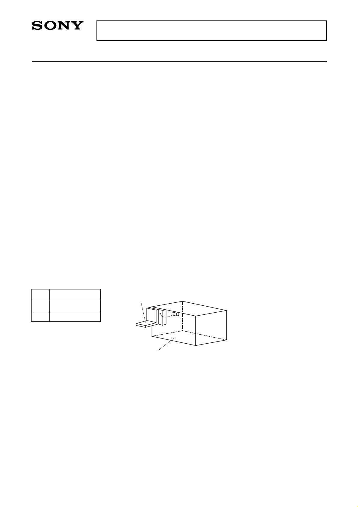
Pin Configuration
– 1 –
E89103A81-PS
Sony reserves the right to change products and specifications without prior notice. This information does not convey any license by
any implication or otherwise under any patents or other right. Application circuits shown, if any, are typical examples illustrating the
operation of the devices. Sony cannot assume responsibility for any problems arising out of the use of these circuits.
SLD301B
No.
1
2
Function
LD cathode
LD anode
2 LD anode
1 LD cathode
Page 2
– 2 –
SLD301B
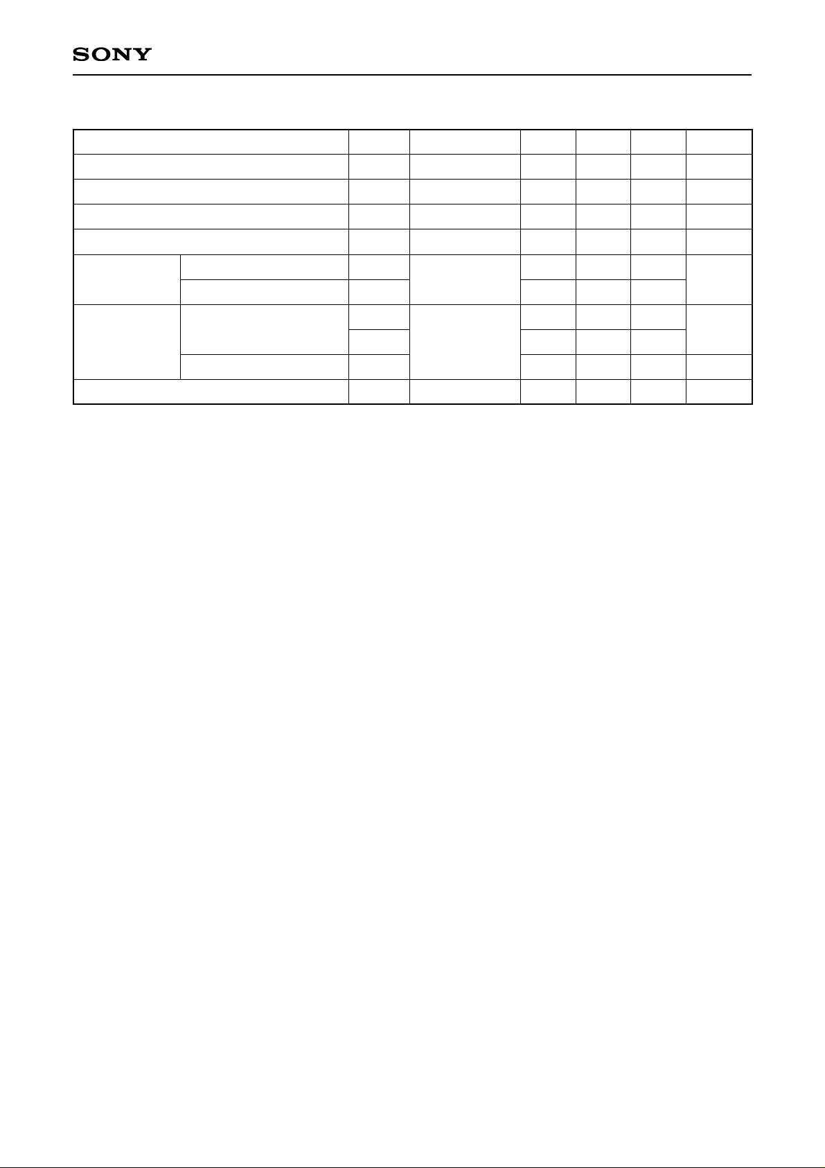
Electrical and Optical Characteristics (Tc = 25°C)
Item Symbol Conditions Min. Typ. Max. Unit
Threshold current
Operating current
Operating voltage
Wavelength
Radiation angle
(F. W. H. M.∗)
Positional
accuracy
Differential efficiency
Ith
Iop
Vop
λp
θ⊥
θ//
∆X
∆Y, ∆Z
∆φ⊥
ηD
PO = 90mW
PO = 90mW
PO = 90mW
PO = 90mW
PO = 90mW
PO = 90mW
770
0.5
150
300
1.9
28
12
0.7
200
400
3.0
840
40
17
±300
±100
±3
mA
mA
V
nm
degree
µm
degree
mW/mA
Perpendicular to junction
Parallel to junction
Position
Angle
∗
F. W. H. M. : Full Width at Half Maximum
Page 3
– 3 –
SLD301B
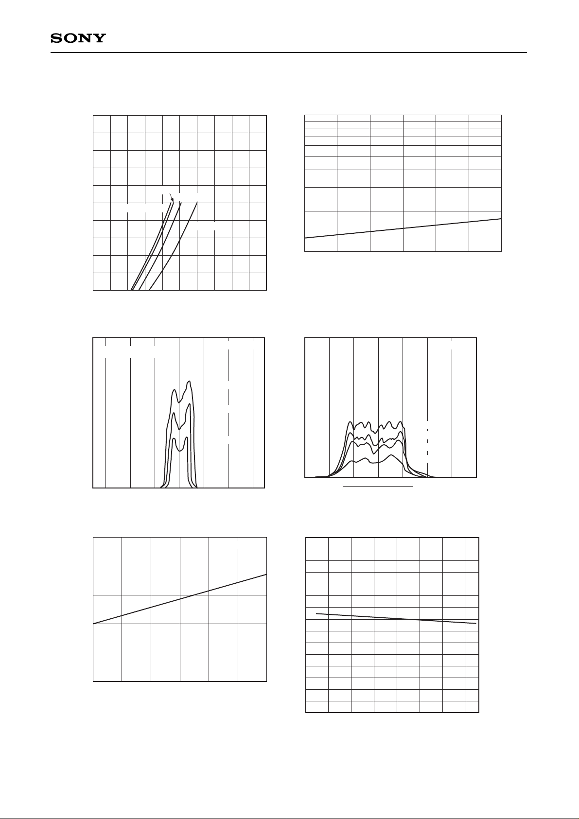
Example of Representative Characteristics
Optical power output vs. Forward current
IF – Forward current [mA]
0 250 500
0
100
200
PO – Optical power output [mW]
Tc = –10°C
Tc = 0°C
Tc = 25°C
Tc = 50°C
Threshold current vs. Temperature characteristics
Tc – Case temperature [°C]
–10 0 10 20 30 40 50
100
500
1000
Ith – Threshold current [mA]
Power dependence of far field pattern
Angle [degree]
–30 –20 –10 0 10 20 30
Radiation intensity (optional scale)
Tc = 25°C
PO = 90mW
PO = 60mW
PO = 30mW
Power dependence of near field pattern
50µm
Radiation intensity (optional scale)
Tc = 25°C
PO = 90mW
PO = 75mW
PO = 50mW
PO = 25mW
Oscillation wavelength vs. Temperature characteristics
Tc – Case temperature [°C]
–10 0 10 20 30 40 50
780
790
830
820
810
800
λp – Oscillation wavelength [nm]
PO = 90mW
Differential efficiency vs. Temperature characteristics
Tc – Case temperature [°C]
–10 0 5040302010
0
0.5
1.0
1.5
ηD – Differential efficiency [mW/mA]
(Parallel to junction)
Page 4
– 4 –
SLD301B
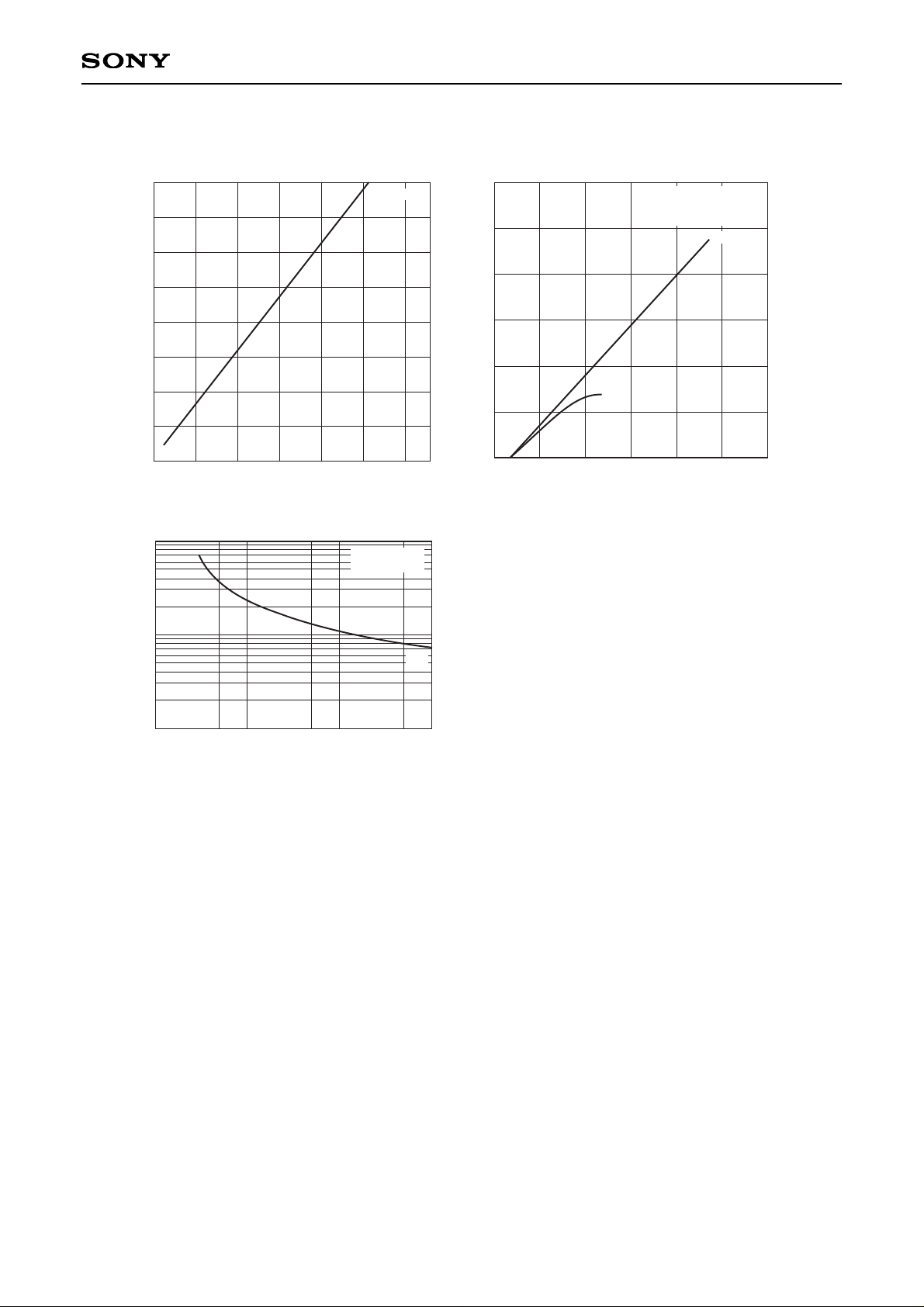
Power dependence of polarization ratio
Po – Optical power output [mW]
0 20 40 60 80 100 120
0
10
30
20
40
Polarization ratio
Tc = 25°C
0.1
0.5
1.0
5.0
10
COD output [W]
Pulse width [µs]
0.1 1.0 5.00.5 10 50 100
Duty = 10%
T
C
= 23°C
CW
0
1.0
3.0
2.0
1.5
0.5
2.5
Po – Optical power output [W]
Optical power output vs. Operating current
Iop – Operating current [A]
0 1.0 2.00.5 1.5 2.5
Pulse width = 1µs
Duty = 10%
Tc = 23°C
PULSE
CW
Pulse width dependence of COD∗ power
∗
COD (Catastrophic Optical Damage)
Page 5
– 5 –
SLD301B
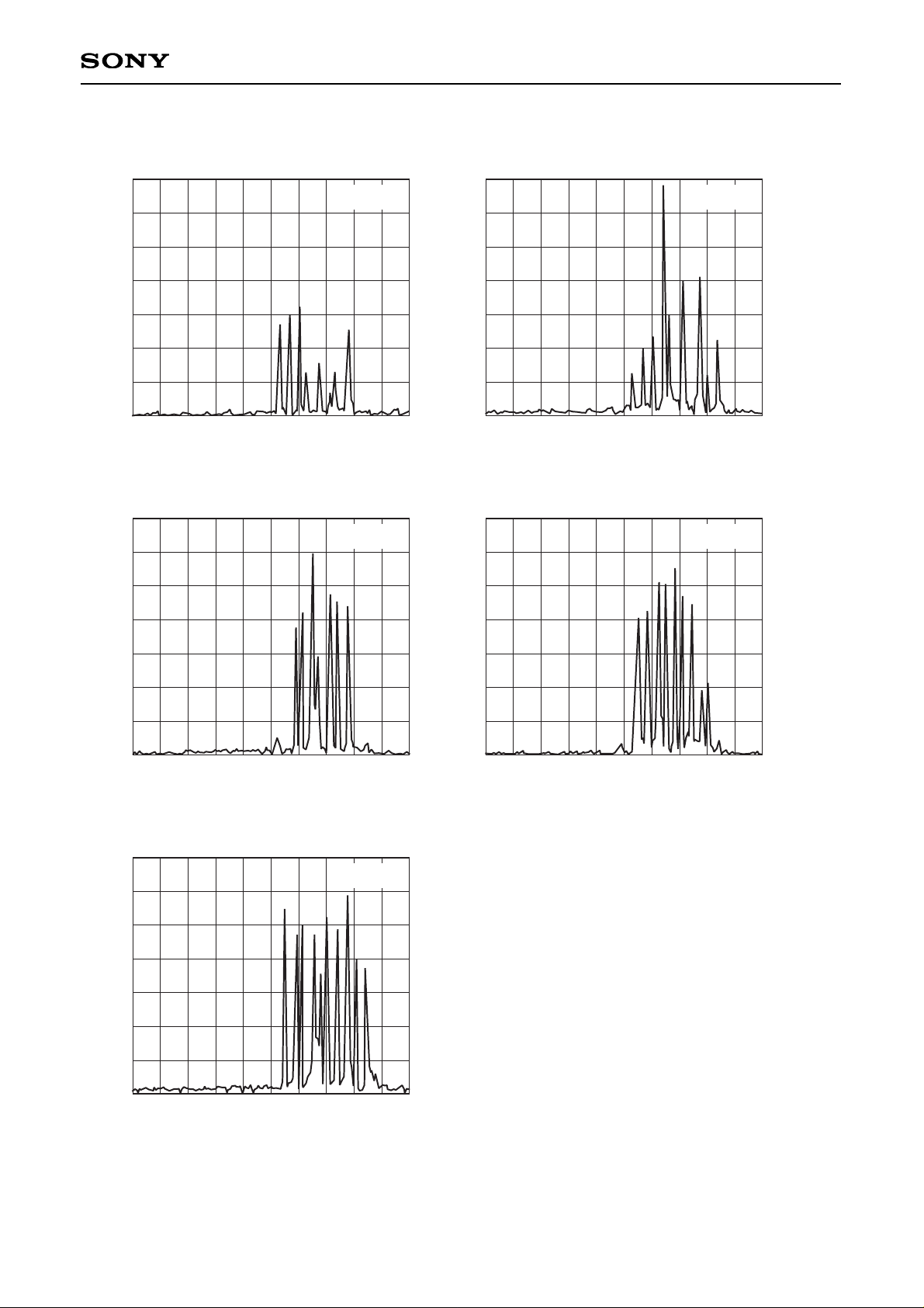
Wavelength [nm]
800 810805
Reletive radiant intensity
Tc = 25°C
Po = 20mW
Wavelength [nm]
800 810805
Reletive radiant intensity
Tc = 25°C
Po = 40mW
Wavelength [nm]
800 810805
Reletive radiant intensity
Tc = 25°C
Po = 80mW
Wavelength [nm]
800 810805
Reletive radiant intensity
Tc = 25°C
Po = 100mW
Wavelength [nm]
800 810805
Reletive radiant intensity
Tc = 25°C
Po = 60mW
Power Dependence of Wavelength
Page 6
– 6 –
SLD301B
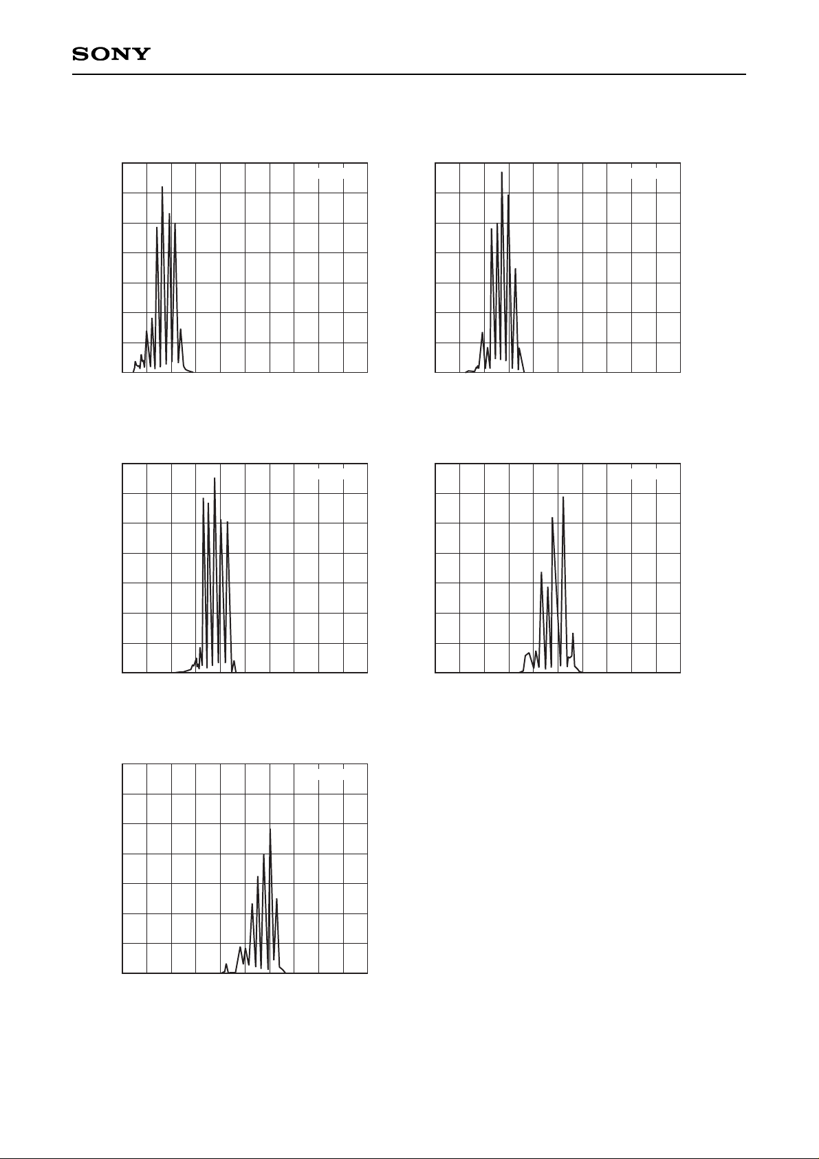
Wavelength [nm]
805 825815
Reletive radiant intensity
Tc = –6°C
Wavelength [nm]
805 825815
Reletive radiant intensity
Tc = 12°C
Wavelength [nm]
805 825815
Reletive radiant intensity
Tc = 23°C
Wavelength [nm]
805 825815
Reletive radiant intensity
Tc = 35°C
Wavelength [nm]
805 825815
Reletive radiant intensity
Tc = 45°C
Temperature Dependence of Wavelength (PO = 90mW)
Page 7
– 7 –
SLD301B
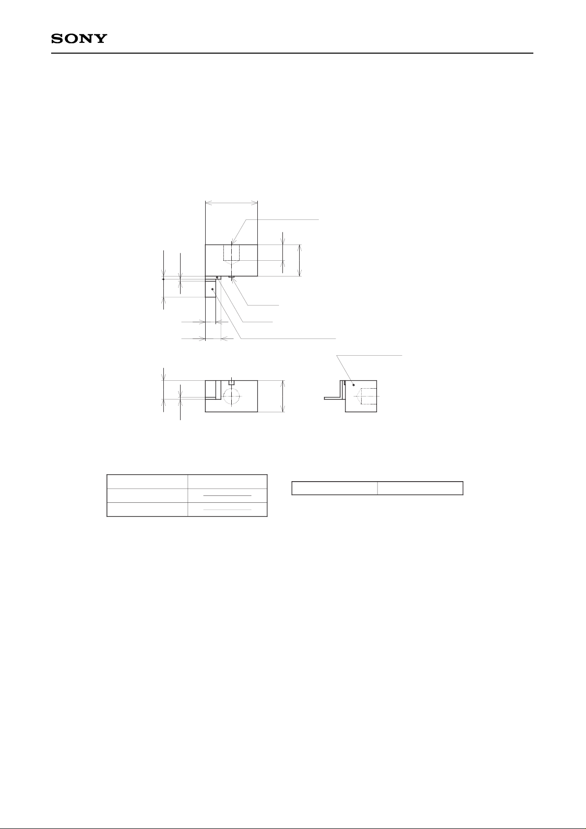
Package Outline Unit: mm
M – 261
5.0 ± 0.1
Ø1.5
for Thermistor
3.0 ± 0.1
1.5
LD Chip
Ceramic
Contact Plate (LD Cathode)
Body (LD Anode)
1.0
1.5
0.2
0.31.7
1.8
0.2
3.0 ± 0.1
SONY CODE
EIAJ CODE
JEDEC CODE
PACKAGE STRUCTURE
M-261
PACKAGE WEIGHT
1g
 Loading...