

Page 1
SLD1231VL
For the availability of this product, please contact the sales office.
High Power Red Laser Diode
Description
The SLD1231VL is a short wavelength high power
laser diode, created as a light source for the nextgeneration high density magneto-optical discs.
Features
• Red visible light (685nm)
• Longitudinal single mode
• High power
(Recommended optical power output: 30mW)
Applications
Magneto-optical discs
Structure
• AlGaInP quantum well structure laser diode
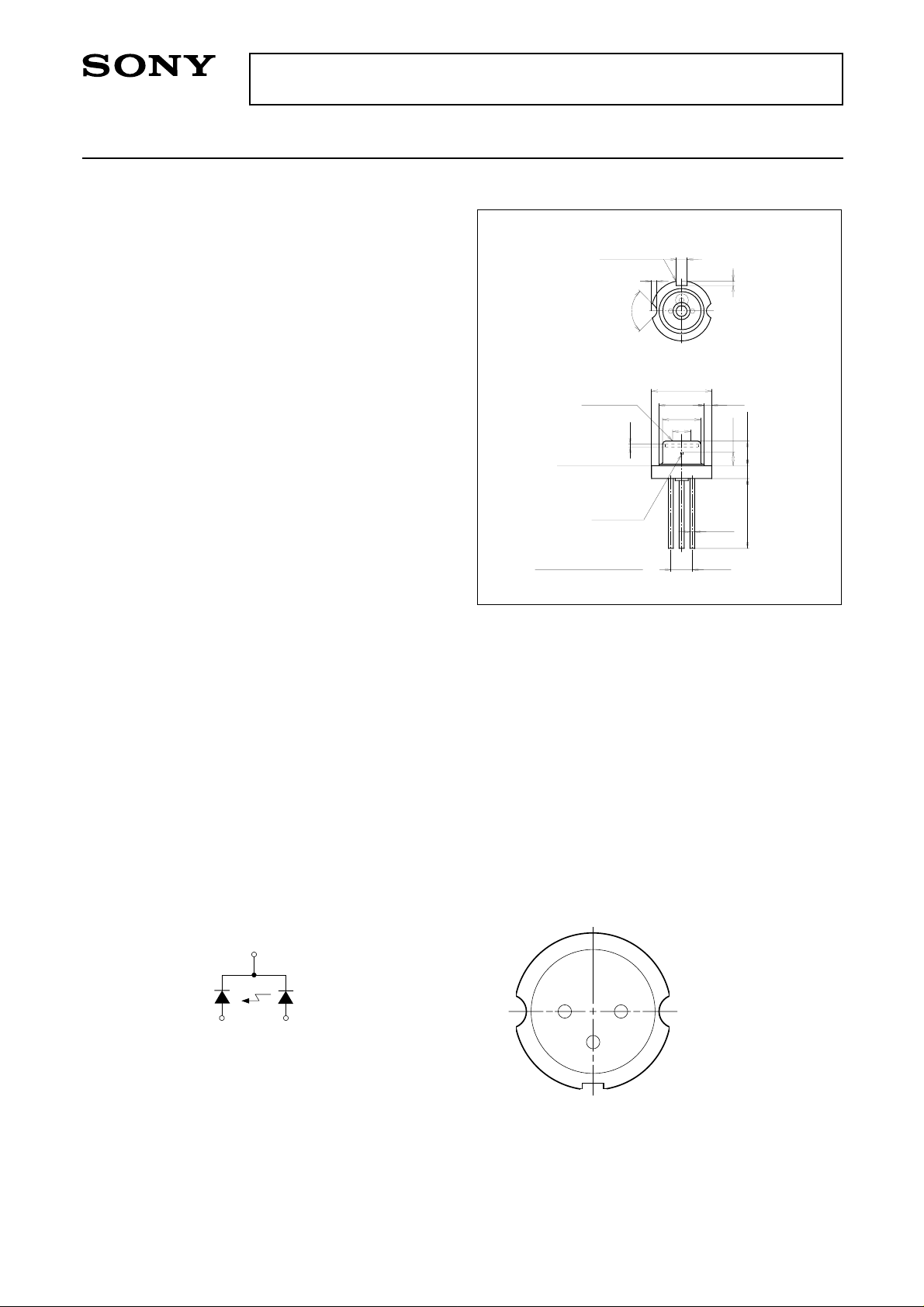
Package Outline
Window Glass
Reference
Plane
∗Optical
Distance = 1.35 ± 0.08
Reference
Slot
LD Chip
& Photo
Diode
90°
0.25
Preliminary
M-274
1.0
0.5
3
2
φ5.6 – 0.025
φ4.4 MAX
φ3.7 MAX
φ1.0 MIN
231
0.4
1
0
0.5 MIN
∗1.26
3 – φ0.45
PCD φ2.0
Unit : mm
2.6 MAX
1.2 ± 0.1
6.5
Recommended Optical Power Output
30mW
Absolute Maximum Ratings
• Optical power output Po 35 mW
• Reverse voltage VR LD 2 V
PD 15 V
• Operating temperature Topr –10 to +50 °C
• Storage temperature Tstg –40 to +85 °C
Connection Diagram Pin Configuration
COMMON
3
PD
LD
2
1
21
3
Bottom View
1. LD anode
2. PD anode
3. COMMON
Sony reserves the right to change products and specifications without prior notice. This information does not convey any license by
any implication or otherwise under any patents or other right. Application circuits shown, if any, are typical examples illustrating the
operation of the devices. Sony cannot assume responsibility for any problems arising out of the use of these circuits.
– 1 –
PE95313-PP
Page 2
SLD1231VL
Electrical and Optical Characteristics (Tc = 25°C) Tc: Case temperature
Item
Threshold current
Operating current
Operating voltage
Wavelength
Radiation
angle
Perpendicular
Parallel
Position
Positional
accuracy
Angle
Symbol Conditions Min. Typ. Max. Unit
Ith
Iop
Vop
λp
θ⊥
θ//
∆X, ∆Y, ∆Z
∆φ⊥
∆φ//
Differential efficiency
Astigmatism
SE
As
Handling Precautions
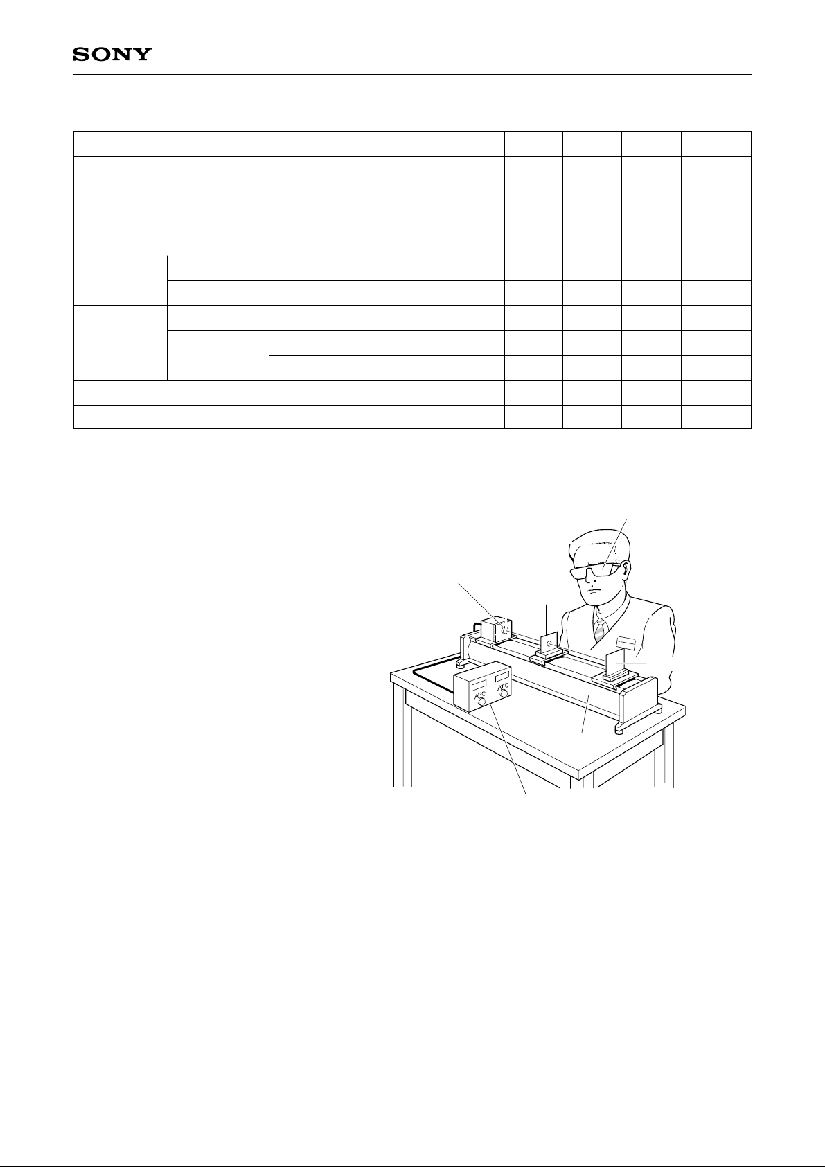
(1) Eye protection against laser beams
The optical output of laser diodes ranges from
several mW to 3W. However the optical power
density of the laser beam at the diode chip
reaches 1MW/cm2. Unlike gas lasers, since
laser diode beams are divergent, uncollimated
laser diode beams are fairly safe at a laser
diode. For observing laser beams, ALWAYS
use safety goggles that block infrared rays.
Usage of IR scopes, IR cameras and
fluorescent plates is also recommended for
monitoring laser beams safely.
Po = 30mW
Po = 30mW
Po = 30mW
Po = 30mW
Po = 30mW
Po = 30mW
Po = 30mW
Po = 30mW
Po = 30mW
Laser diode
Lens
670
19
6
0.15
Optical
material
Optical board
55
95
2.4
685
23
9
70
120
3.0
699
27
12
degree
degree
±80
±3
±3
0.60
5
Safety goggles for
protection from laser beam
1.0
10
IR fluorescent plate
degree
degree
mW/mA
mA
mA
V
nm
µm
µm
Optical power output control device
Temperature control device
(2) Prevention of surge current and electrostatic discharge
Laser diode is most sensitive to electrostatic discharge among semiconductors. When a large current is
passed through the laser diode even for an extremely short time (in the order of nanosecond), the strong light
emitted from the laser diode promotes deterioration and then laser diodes are destroyed. Therefore, note that
the surge current should not flow the laser diode driving circuit from switches and others. Also, if the laser
diode is handled carelessly, it may be destructed instantly because electrostatic discharge is easily applied by
a human body. Be great careful about excess current and electrostatic discharge.
– 2 –
Page 3
Example of Representative Characteristics
SLD1231VL
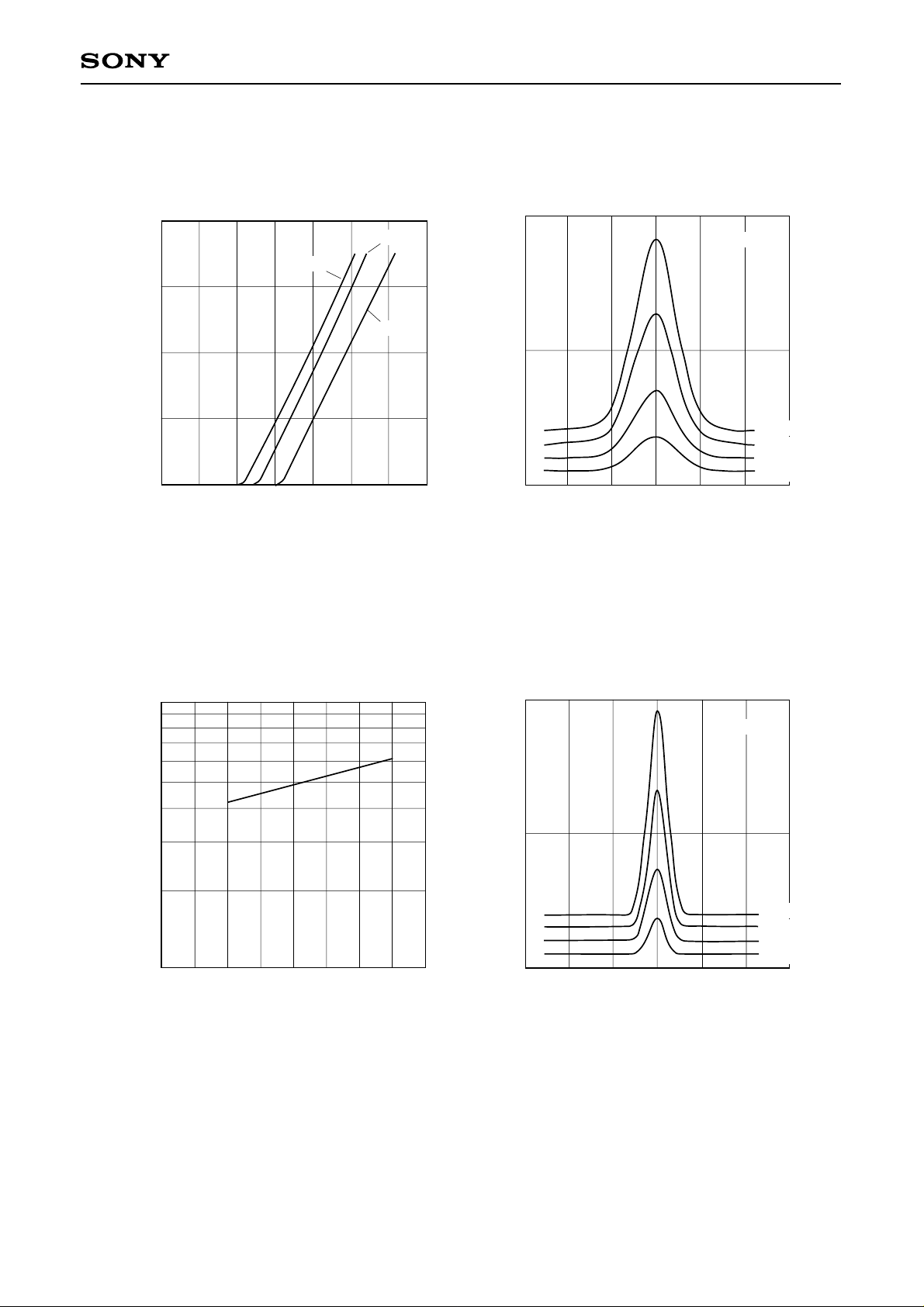
Optical power output vs. Forward current characteristics
40
TC = 25°C
TC = 0°C
30
TC = 50°C
20
10
Po — Optical power output [mW]
0
120100800 20 40 60 140
IF — Forward current [mA]
Power dependence of far field pattern
(Perpendicular to junction)
TC = 25°C
Relative radiant intensity
–60 –40 –20 60
0
Angle [degree]
4020
Po = 30mW
Po = 20mW
Po = 10mW
Po = 5mW
Threshold current vs. Temperature characteristics
100
50
Ith — Threshold current [mA]
0
504030–20 –10 0 20 6010
Tc — Case temperature [°C]
Power dependence of far field pattern
(Parallel to junction)
Relative radiant intensity
Angle [degree]
TC = 25°C
Po = 30mW
Po = 20mW
Po = 10mW
Po = 5mW
40200–60 –40 –20 60
– 3 –
Page 4
Tc = 25°C
SLD1231VL
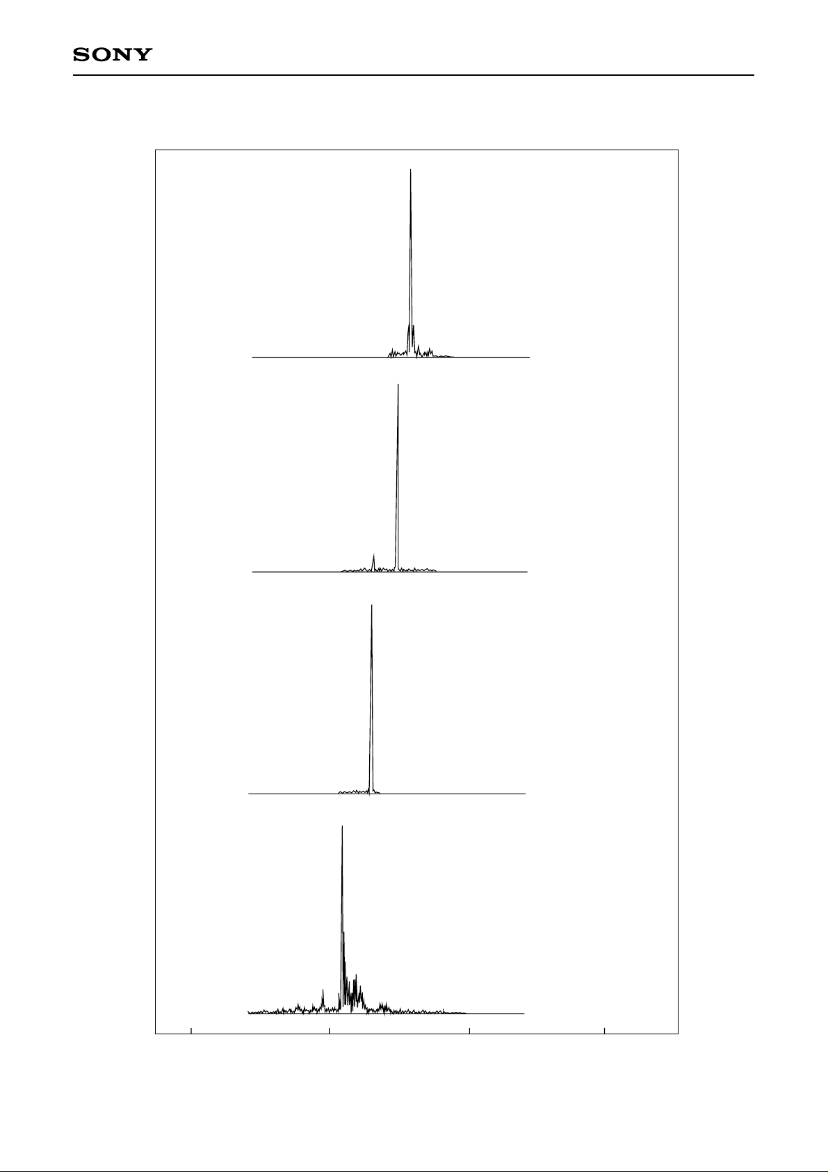
Power dependence of spectrum
Po = 30mW
Po = 20mW
intensity
Relative radiant
Po = 10mW
Po = 5mW
680
685 690 695
λ — Wavelength [nm]
– 4 –
Page 5
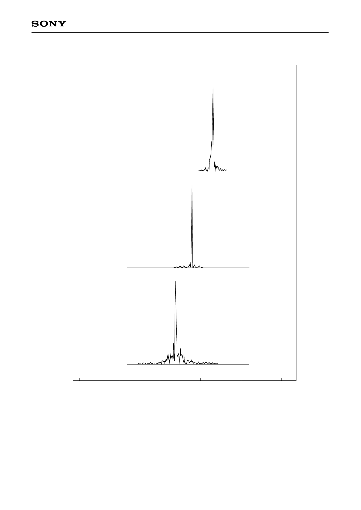
Po = 30mW
SLD1231VL
Temperature dependence of spectrum
Tc = 50°C
intensity
Relative radiant
660
Tc = 25°C
Tc = 0°C
670 680 690 700 710
λ — Wavelength [
nm]
– 5 –
 Loading...