

Page 1
Timing Circuit
SLC555
The SLC555 monolithic timing circuit is a highly stable controller
capable of producing accurate time delays, or oscillation.
• Direct Replacement for NE555 Timers
• Timing From Microseconds Through Hours
• Operates in Both Astable and Monostable Modes
• High Current Output Can Source or Sink 200 mA
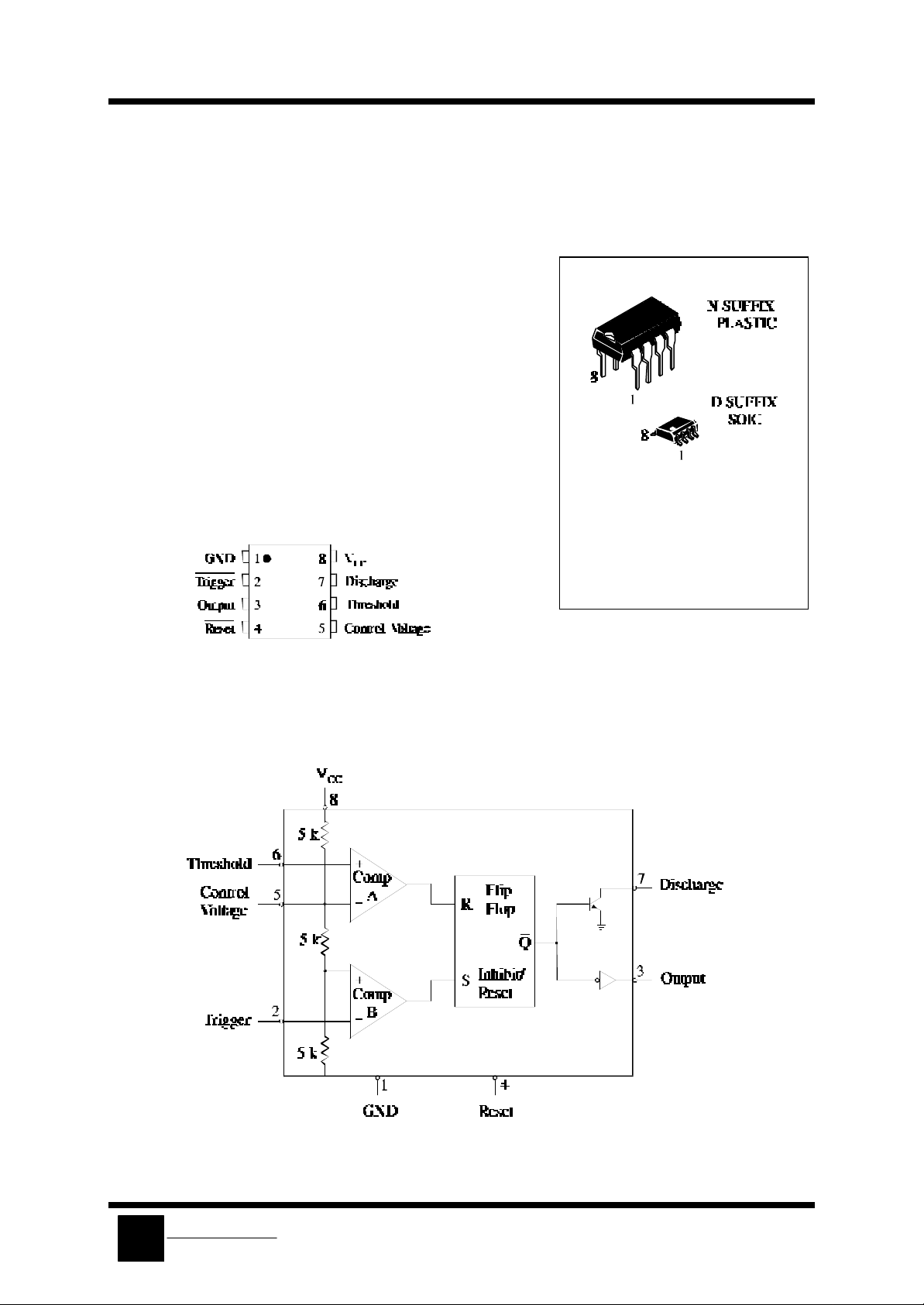
PIN ASSIGNMENT
ORDERING INFORMATION
SLC555N Plastic
SLC555D SOIC
TA = -10° to 70° C for
all packages
LOGIC DIAGRAM
System Logic
SLS
Semiconductor
Page 2
SLC555
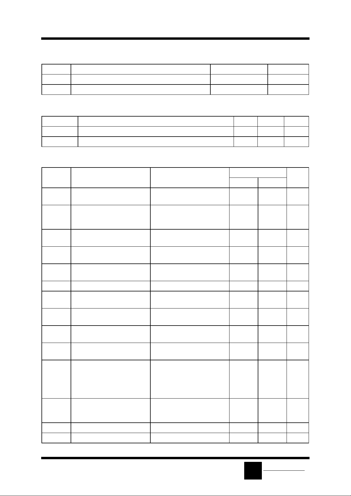
MAXIMUM RATINGS*
Symbol Parameter Value Unit
VCC Supply Voltage 18 V
Tstg Storage Temperature -60 to +85 °C
RECOMMENDED OPERATING CONDITIONS
Symbol Parameter Min Max Unit
VCC Supply Voltage 4.5 16 V
TA Operating Temperature, All Package Types -10 +70 °C
ELECTRICAL CHARACTERISTICS(T
=+25°C)
A
Symbol Parameter Test Condit ions Guaranteed Limits Unit
Min Max
ICC Supply Current VCC=5.0 V, RL =∞
VCC=15 V, RL=∞
Timing Error R=1.0 kΩ to 100 kΩ
6.0
15
4 %
Initial Accuracy C = 0.1 µF
VCC=5.0 V and VCC=15 V
Vth Threshold Voltage VCC=5.0 V
VCC=15 V
VT Trigger Voltage VCC=5.0 V
VCC=15 V
IT Trigger Current V02=0 V, VCC=15 V
V02=15 V, VCC=15 V
2.6
9
1.1
4.5
-2
4.0
11
2.2
5.6
0.5
VR Reset Voltage VCC=15 V 0.4 1.0 V
IR Reset Current V04=0 V, VCC=15 V
V04=15 V, VCC=15 V
Ith Threshold Current (Note 1) V06=0 V, VCC=15 V
V06=10 V, VCC=15 V
I
Discharge Leakage Current (Pin
dis
VCC=15 V, V07=15 V 100 nA
-0.4
0.5
-0.5
0.25
7)
mA
V
V
µA
mA
µA
µA
V
Control Voltage Level VCC=15 V
REF
VCC=5.0 V
VOL Output Voltage Low (VCC=15 V)
I
=10 mA,
sink
I
=50 mA,
sink
I
=100 mA,
sink
VCC=5.0 V, I
VOH Output Voltage High I
t
Rise Time of Output VCC=15 V 150 ns
OLH
t
Fall Time of Output VCC=15 V 150 ns
OHL
=200 mA,VCC=15 V
source
I
=100 mA, VCC=15 V
source
I
=100 mA, VCC=5.0 V
source
=5.0 mA
sink
9.0
2.6
12
12.75
2.75
SLS
11
4.0
0.25
0.75
2.3
0.35
V
System Logic
Semiconductor
V
V
Page 3

Note 1. This will determine the maximum value of RA + RB for 15 V operation.
The maximum total R=20 MΩ.
IL34119
3
 Loading...