

Page 1
SL2418
System Logic
Semiconductor
SLS
Telephone Tone Ringer with Bridge Diode
The SL2418 is a monolithic integrated circuit telephone tone ringer
with bridge diode, when coupled with an appropriate transducer, it
replaces the electro-mechanical bell. The device is designed for use
with either a piezo transducer or an inexpensive transformer coupled
speaker to produce a pleasing tone composed of a high frequency (fR)
alternating with a low frequency (fL) resulting in a warble frequency.
The supply voltage is obtained from the AC ring signal and the circuit
is designed so that noise on the line or variation of the ringing signal
can not affect correct operation of the device.
• On chip high voltage full wave diode bridge rectifier
• Low current consumption, in order to allow the parallel operation
of the 4 devices
• Low external component count
• Tone and switching frequencies adjustable by external
components
• High noise immunity due to built-in voltage-current hysteresis
• Activation voltage adjustable
• Internal zener diodes to protect against over voltages
• Ringer impedance adjustable with external components
ORDERING INFORMATION
SL2418N Plastic
SL2418D SOIC
TA = -20° to 70° C
for package
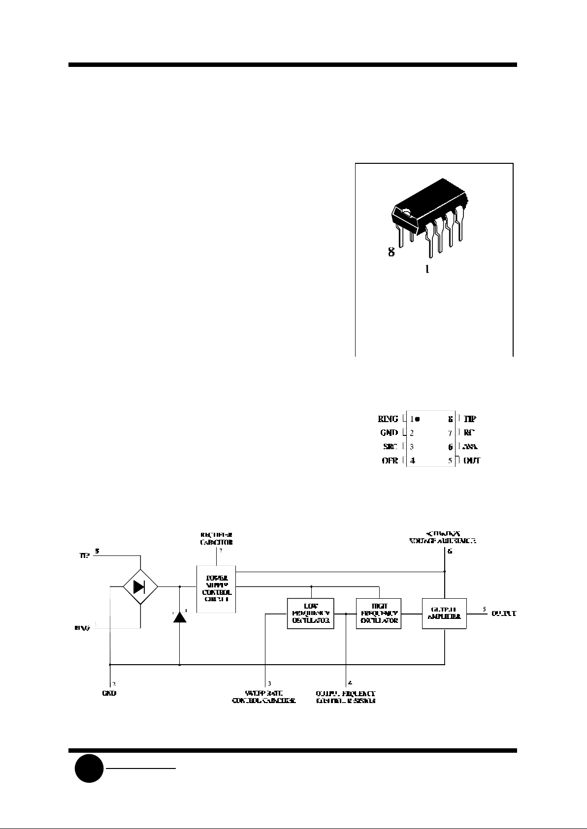
PIN ASSIGNMENT
BLOCK DIAGRAM
Page 2
SL2418
System Logic
Semiconductor
SLS
MAXIMUM RATINGS* (TA = 25°C)
Symbol Parameter Value Unit
VTP Calling Voltage (f = 50 Hz) Continuous 120 Vrms
VTP Calling Voltage (f = 50 Hz) 5 Sec ON/10 Sec OFF 200 Vrms
ICC Supply Current 22 mA
Tstg Storage and Junction Temperature -65 to +150 °C
*
Maximum Ratings are those values beyond which damage to the device may occur.
Functional operation should be restricted to the Recommended Operating Conditions.
RECOMMENDED OPERATING CONDITIONS
Symbol Parameter Min Max Unit
VCC Supply Voltage 26 V
TA Operating Temperatur e -20 +70 °C
This device contains protection circuitry to guard against damage due to high static voltages or electric
fields. However, precautions must be taken to avoid applications of any voltage higher than maximum rated
voltages to this high-impedance circuit. For proper operation, VIN and V
OUT
should be constrained to the range
GND≤(VIN or V
OUT
)≤VCC.
Unused inputs must always be tied to an appropriate logic voltage level (e.g., either GND or VCC).
Unused outputs must be left open.
ELECTRICAL CHARACTERISTICS(T
A
= 25°C)
Symbol
Parameter
Test Conditions
Guaranteed Limits
Unit
Min Typ Max
ICC Current Consumption without
Load
VS=8.8 to 26 V 1.8 mA
VON Activiation Voltage 12.2 13 V
V
ONR
Activiation Voltage Range RA = 1 KΩ 8 10 V
V
SUS
Sustaining Voltage 8 8.8 V
RD Differential Resistance in Off
Condition
6.4 KΩ
V
OUT
Output Voltage Swing VCC-3 V
I
OUT
Short Circuit Current VS = 26 V 35 mA
Page 3
SL2418
System Logic
Semiconductor
SLS
AC CHARACTERISTICS
Symbol
Parameter
Test Conditions
Guaranteed Limits
Unit
Min Typ Max
fH1
fH2
Output Frequencies
fH1
fH2
V
CC
= 26 V, R1 = 14 KΩ
VCC = 0 V
VCC = 6 V
2300
1700
Hz
Hz
fH1 Range R1 = 27 KΩ to 1.7 KΩ 0.1 15 KHz
fL Sweep Frequency R1 = 14 KΩ, C1 = 100 nF 10 Hz
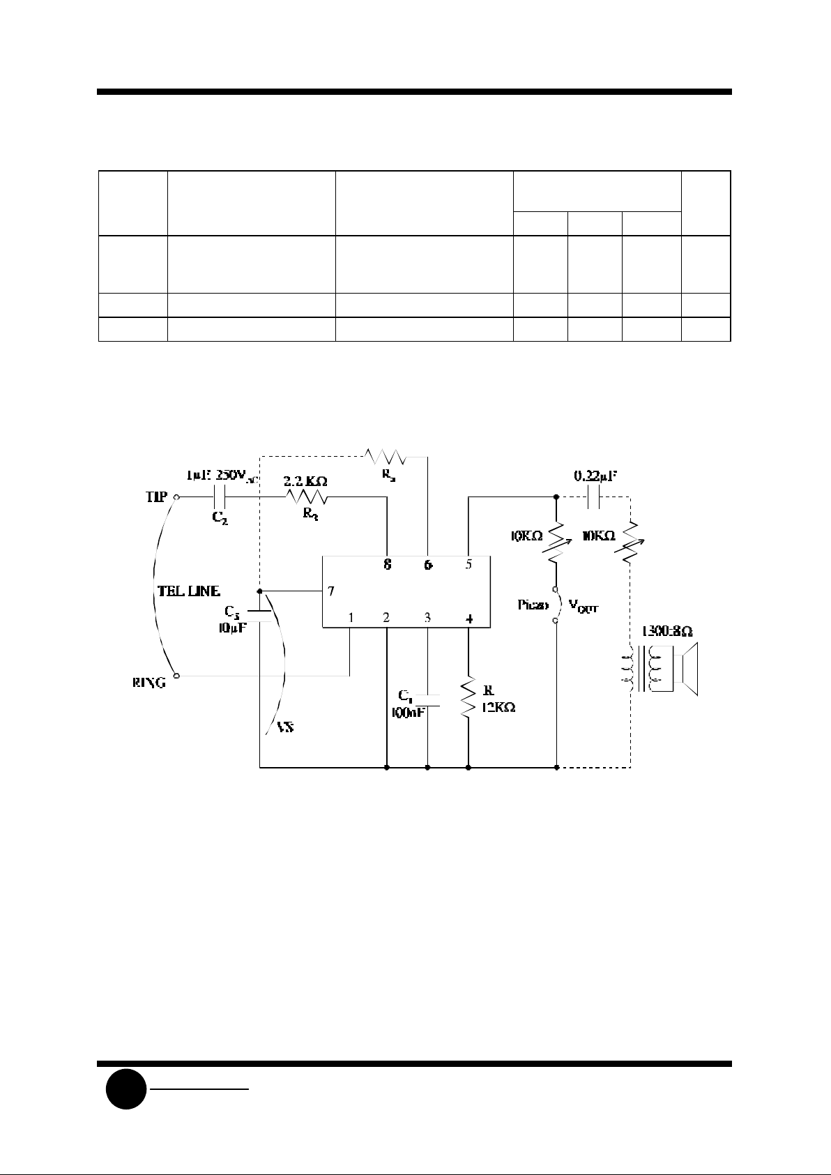
TEST AND APPLICATION CIRCUIT
f1 = 3.22 •104 / R1 (KΩ); f2 = 5/7 f1; f
sweep
= 1000 / C1(nF)
DESCRIPTION
The SL2418 tone ringer derives its power supply by rectifying the AC ringing signal. It uses this power to
activate two tone generators. The two tone frequencies generated are switched by internal oscillator in a fast
sequence and made audible across an output amplifier in the loudspeaker; both tone frequencies and the
switching frequency can be externally adjusted.
The device can drive either directly a piezo ceramic converter (buzzer) or small loudspeaker. In case of using
a loud-speaker, a transformer is needed.
An internal shunt voltage regulator provides DC voltage to the output stage, low frequency oscillator, and
high frequency oscillator. To protect the IC from telephone line transients, a zener Diode is included.
 Loading...