

Page 1
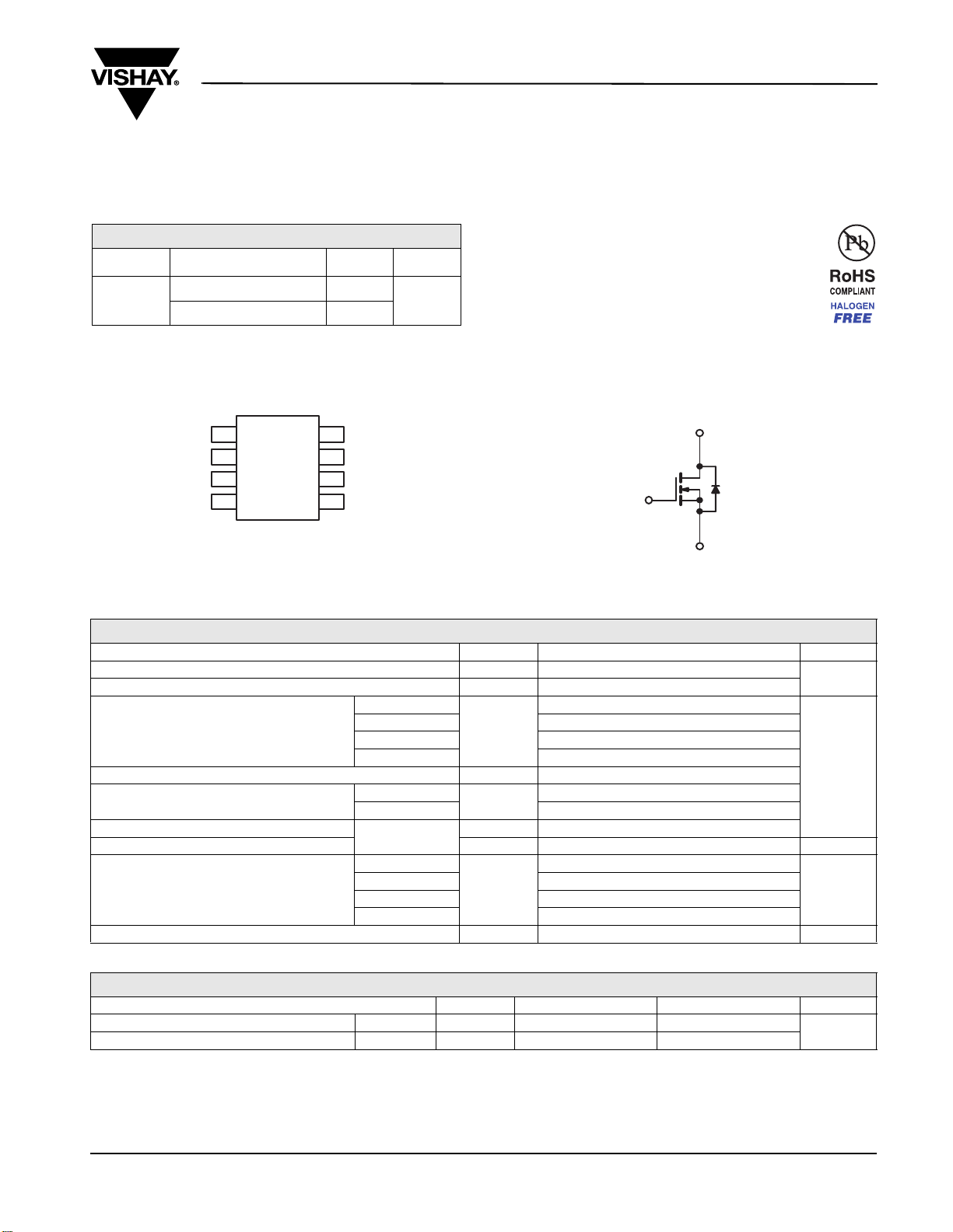
New Product
D
N-Channel 20-V (D-S) MOSFET
Si4136DY
Vishay Siliconix
PRODUCT SUMMARY
VDS (V) R
0.002 at V
20
0.0025 at V
DS(on)
(Ω)
GS
GS
= 10 V
= 4.5 V
a
I
(A)
D
46
Qg (Typ.)
34 nC
41
FEATURES
• Halogen-free According to IEC 61249-2-21
• TrenchFET
• 100 % R
®
Power MOSFET
and UIS Tested
g
APPLICATIONS
• OR-ing
• DC/DC
SO-8
SD
1
SD
2
SD
3
GD
4
Top View
Ordering Information: Si4136DY-T1-GE3 (Lead (Pb)-free and Halogen-free)
8
7
6
5
G
N-Channel MOSFET
S
ABSOLUTE MAXIMUM RATINGS TA = 25 °C, unless otherwise noted
Parameter Symbol Limit Unit
Drain-Source Voltage
Gate-Source Voltage
T
Continuous Drain Current (T
= 150 °C)
J
T
T
TA = 70 °C
Pulsed Drain Current
Continuous Source-Drain Diode Current
Single Pulse Avalanche Current
Avalanche Energy
T
T
L = 0.1 mH
T
Maximum Power Dissipation
T
T
TA = 70 °C
Operating Junction and Storage Temperature Range
= 25 °C
C
= 70 °C
C
= 25 °C
A
= 25 °C
C
= 25 °C
A
= 25 °C
C
= 70 °C
C
= 25 °C
A
V
DS
V
GS
20
± 20
V
46
I
D
I
DM
I
S
I
AS
E
AS
31
24.7
3.1
37
70
30
45
7
b, c
b, c
b, c
A
mJ
7.8
P
D
, T
T
J
stg
3.5
2.2
5
b, c
b, c
W
- 55 to 150 °C
THERMAL RESISTANCE RATINGS
Parameter Symbol Typical Maximum Unit
Maximum Junction-to-Ambient
Maximum Junction-to-Foot (Drain) Steady State
Notes:
a. Based on T
b. Surface Mounted on 1" x 1" FR4 board.
= 25 °C.
C
c. t = 10 s.
d. Maximum under Steady State conditions is 80 °C/W.
Document Number: 64718
S09-0139-Rev. A, 02-Feb-09
b, d
t ≤ 10 s
R
thJA
R
thJF
29 35
13 16
°C/W
www.vishay.com
1
Page 2
New Product
Si4136DY
Vishay Siliconix
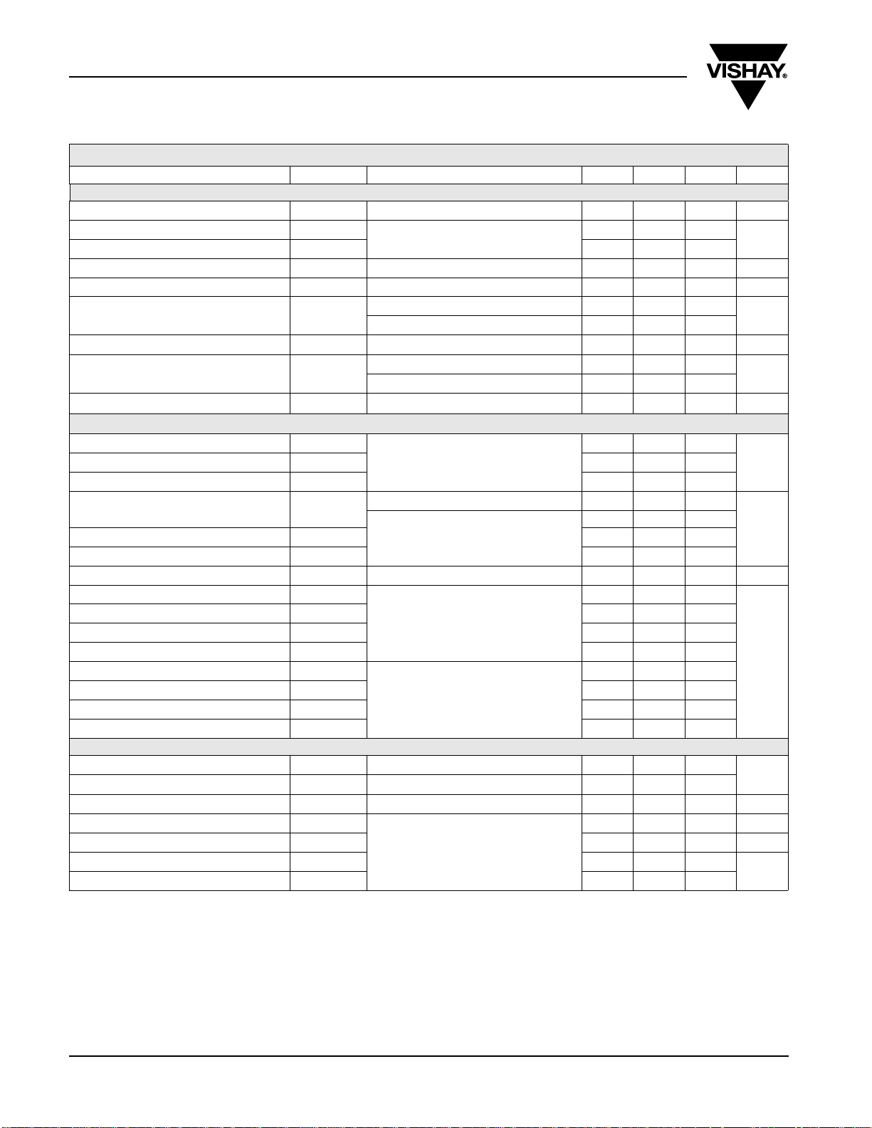
SPECIFICATIONS TJ = 25 °C, unless otherwise noted
Parameter Symbol Test Conditions Min. Typ. Max. Unit
Static
V
Drain-Source Breakdown Voltage
V
Temperature Coefficient ΔVDS/T
DS
V
Temperature Coefficient ΔV
GS(th)
Gate-Source Threshold Voltage
Gate-Source Leakage
Zero Gate Voltage Drain Current
On-State Drain Current
Drain-Source On-State Resistance
Forward Transconductance
Dynamic
b
a
a
a
Input Capacitance
Reverse Transfer Capacitance
Total Gate Charge
Gate-Source Charge
Gate-Drain Charge
Gate Resistance
Tur n -O n De l ay Ti m e
Rise Time
Turn-Off Delay Time
Fall Time
Tur n -O n De l ay Ti m e
Rise Time
Turn-Off Delay Time
Fall Time
V
DS
J
GS(th)/TJ
V
GS(th)
I
GSS
I
DSS
I
V
D(on)
R
DS(on)
g
fs
C
iss
C
oss
C
rss
Q
g
Q
gs
Q
gd
R
g
t
d(on)
t
r
t
d(off)
t
f
t
d(on)
t
r
t
d(off)
t
f
Drain-Source Body Diode Characteristics
Continuous Source-Drain Diode Current
Pulse Diode Forward Current
a
Body Diode Voltage
Body Diode Reverse Recovery Time
Body Diode Reverse Recovery Charge
Reverse Recovery Fall Time
Reverse Recovery Rise Time
I
S
I
SM
V
SD
t
rr
Q
rr
t
a
t
b
Notes
a. Pulse test; pulse width ≤ 300 µs, duty cycle ≤ 2 %
b. Guaranteed by design, not subject to production testing.
V
DS
V
V
DS
V
DS
I
D
I
D
IF = 10 A, dI/dt = 100 A/µs, TJ = 25 °C
GS
VDS = V
V
DS
V
DS
= 20 V, V
DS
V
GS
V
GS
V
DS
= 10 V, V
DS
= 10 V, V
= 10 V, V
V
DD
≅ 10 A, V
V
DD
≅ 10 A, V
= 0 V, V
= 0 V, ID = 250 µA
ID = 250 µA
, ID = 250 µA
GS
= ± 20 V
GS
= 20 V, V
GS
≥ 5 V, V
= 0 V
GS
= 0 V, TJ = 55 °C
= 10 V
GS
= 10 V, ID = 15 A
= 4.5 V, ID = 10 A
= 10 V, ID = 15 A
20 V
19
- 6
1.0 2.2 V
± 100 nA
1
10
30 A
0.00155 0.002
0.00195 0.0025
85 S
4560
= 0 V, f = 1 MHz
GS
1285
545
= 10 V, ID = 20 A
GS
73 110
34 50
= 4.5 V, ID = 20 A
GS
11
9
f = 1 MHz 0.3 1.5 3 Ω
34 60
= 10 V, RL = 1 Ω
= 4.5 V, Rg = 1 Ω
GEN
26 45
50 90
23 40
13 25
= 10 V, RL = 1 Ω
= 10 V, Rg = 1 Ω
GEN
11 22
43 70
918
TC = 25 °C
7
70
IS = 2 A
0.69 1.1 V
31 47 ns
24 36 nC
15.5
15.5
mV/°C
µA
Ω
pFOutput Capacitance
nC
ns
A
ns
Stresses beyond those listed under “Absolute Maximum Ratings” may cause permanent damage to the de vice. These are stress rating s only, and functiona l operation
of the device at these or any other conditions beyond those indicated in the operational sections of the specifications is not implied. Exposure to absolute maximum
rating conditions for extended periods may affect device reliability.
www.vishay.com
2
Document Number: 64718
S09-0139-Rev. A, 02-Feb-09
Page 3
New Product
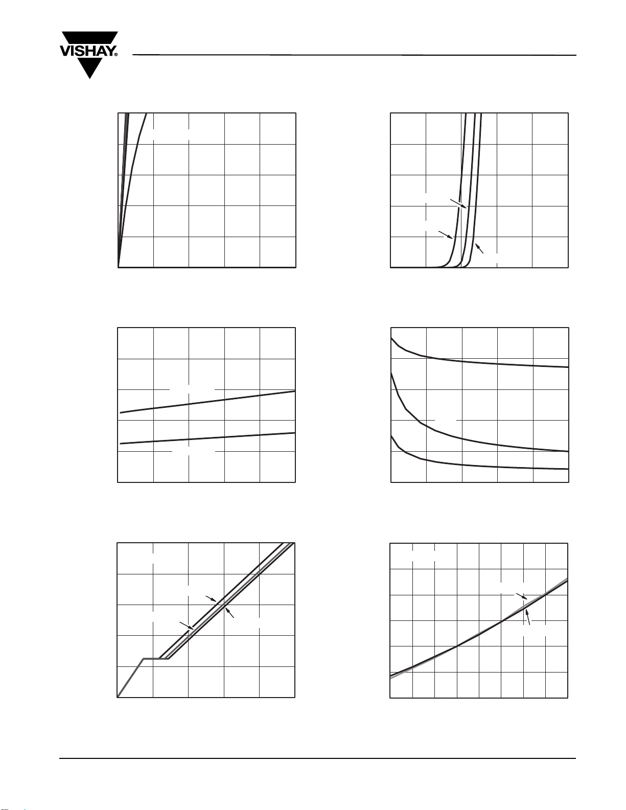
TYPICAL CHARACTERISTICS 25 °C, unless otherwise noted
Si4136DY
Vishay Siliconix
70
56
42
28
- Drain Current (A)I
D
14
0
0.0 0.5 1.0 1.5 2.0 2.5
VGS=10thru 3 V
- Drain-to-Source Voltage (V)
V
DS
Output Characteristics
0.0030
0.0026
0.0022
VGS=4.5V
10
8
6
4
- Drain Current (A)I
D
2
0
TC= 25 °C
TC= 125 °C
TC= - 55 °C
012345
- Gate-to-Source Voltage (V)
V
GS
Transfer Characteristics
6000
C
4800
3600
iss
- On-Resistance (Ω)R
0.0018
DS(on)
0.0014
0.0010
01428 42 56 70
VGS=10V
ID- Drain Current (A)
On-Resistance vs. Drain Current and Gate Voltage
10
ID=20A
8
VDS=5V
6
VDS=10V
4
- Gate-to-Source Voltage (V)
GS
2
V
0
0 1530456075
Qg- Total Gate Charge (nC)
VDS=15V
Gate Charge
2400
C - Capacitance (pF)
1200
C
0
0.0 2.4 4.8 7.2 9.6 12.0
C
oss
rss
VDS- Drain-to-Source Voltage (V)
Capacitance
1.8
ID=15A
1.6
1.4
1.2
- On-ResistanceR
(Normalized)
1.0
DS(on)
0.8
0.6
- 50 - 25 0 25 50 75 100 125 150
T
-Junction Temperature (°C)
J
VGS=10V
On-Resistance vs. Junction Temperature
VGS=4.5V
Document Number: 64718
S09-0139-Rev. A, 02-Feb-09
www.vishay.com
3
Page 4
New Product
Si4136DY
Vishay Siliconix
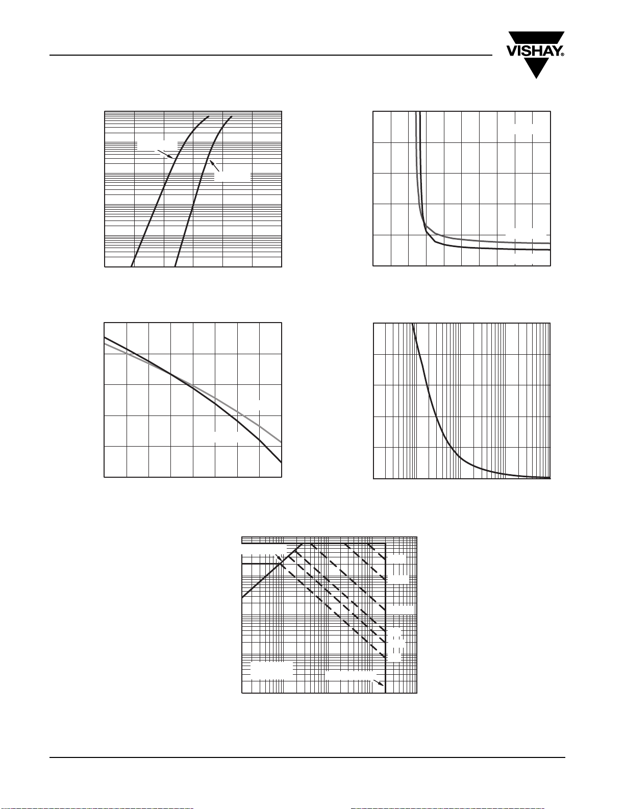
TYPICAL CHARACTERISTICS 25 °C, unless otherwise noted
100
10
TJ= 150 °C
0.015
ID=15A
0.012
1
0.1
- Source Current (A)I
S
0.01
0.001
0.0 0.2 0.4 0.6 0.8 1.0 1.2
-Source-to-Drain Voltage (V)
V
SD
TJ= 25 °C
Source-Drain Diode Forward Voltage
0.5
0.2
- 0.1
Variance (V)V
- 0.4
GS(th)
ID= 250 µA
- 0.7
ID=5mA
0.009
0.006
- On-Resistance (Ω)
DS(on)
R
0.003
0.000
012345678 910
VGS- Gate-to-Source Voltage (V)
TJ= 125 °C
TJ=25 °C
On-Resistance vs. Gate-to-Source Voltage
200
160
120
Power (W)
80
40
- 1.0
- 50 - 25 0 25 50 75 100 125 150
www.vishay.com
4
TJ- Temperature (°C)
Threshold Voltage
- Drain Current (A)
D
I
100
Limited byR
10
1
0.1
0.01
0.01
* V
*
DS(on)
TA= 25 °C
Single Pulse
0.1 1 10
- Drain-to-Source Voltage (V)
V
DS
> minimum VGSat which R
GS
BVDSS Limited
Safe Operating Area, Junction-to-Ambient
0
DS(on)
0.1
Time (s)
Single Pulse Power, Junction-to-Ambient
1ms
10 ms
100 ms
1s
10 s
DC
100
is specified
Document Number: 64718
S09-0139-Rev. A, 02-Feb-09
011100.00.01
Page 5
New Product
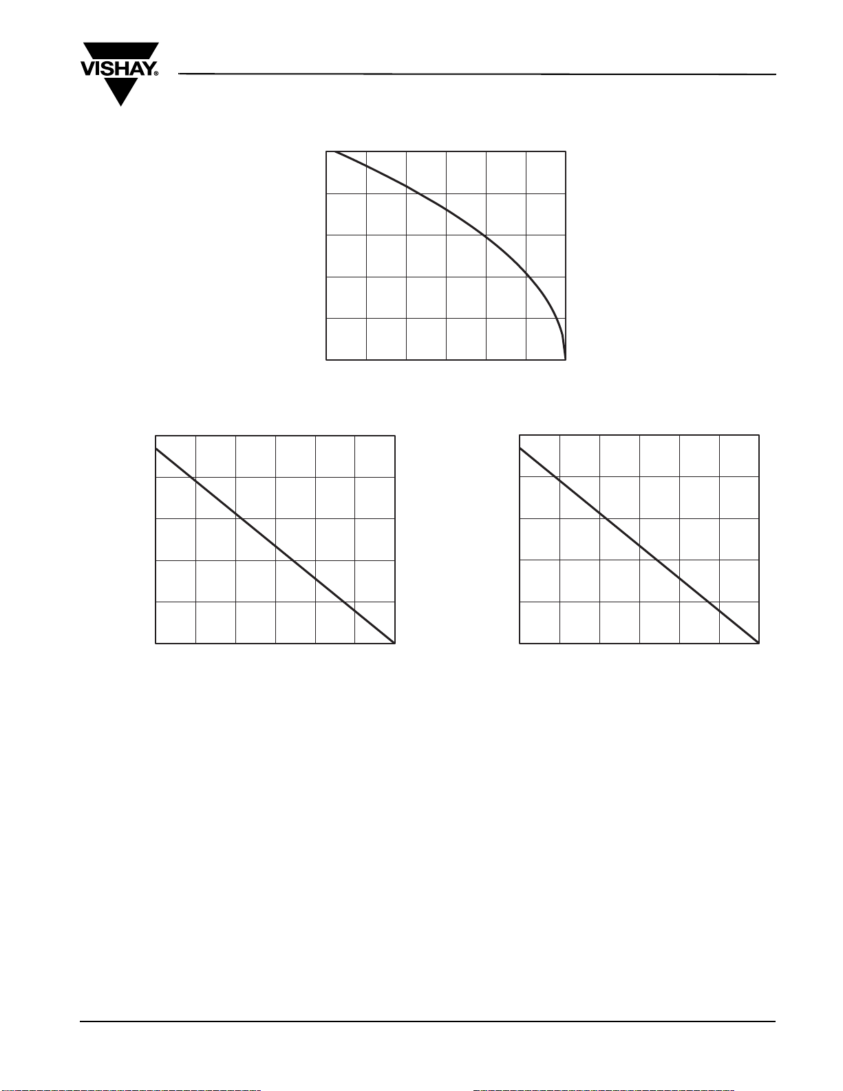
TYPICAL CHARACTERISTICS 25 °C, unless otherwise noted
50
40
30
20
- Drain Current (A)
D
I
10
0
0 25 50 75 100 125 150
- Case Temperature (°C)
T
C
Current Derating*
Si4136DY
Vishay Siliconix
10
8
6
Power (W)
4
2
0
0 25 50 75 100 125 150
T
- Case Temperature (°C)
C
Power Derating, Junction-to-Case
* The power dissipation PD is based on T
dissipation limit for cases where additional heatsinking is used. It is used to determine the current rating, when this rating falls below the package
= 150 °C, using junction-to-case thermal resistance, and is more useful in settling the upper
J(max)
2.0
1.6
1.2
Power (W)
0.8
0.4
0.0
0 25 50 75 100 125 150
-Ambient Temperature (°C)
T
A
Power Derating, Junction-to-Ambient
limit.
Document Number: 64718
S09-0139-Rev. A, 02-Feb-09
www.vishay.com
5
Page 6
New Product
Si4136DY
Vishay Siliconix
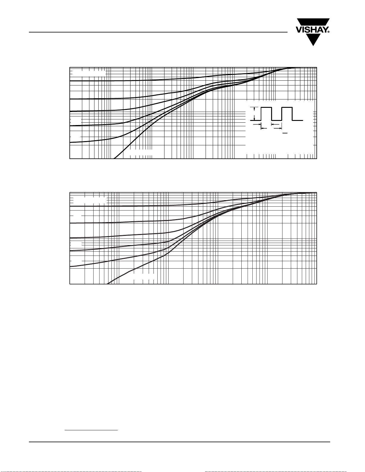
TYPICAL CHARACTERISTICS 25 °C, unless otherwise noted
1
Duty Cycle = 0.5
0.2
0.1
0.1
0.01
0.05
0.02
Single Pulse
-3
10
-2
10
-1
Square WavePulse Duration (s)
Normalized Thermal Transient Impedance, Junction-to-Ambient
Thermal Impedance
Normalized Effective Transient
Notes:
P
DM
t
1
t
1. Duty Cycle, D =
2. Per Unit Base = R
3. T
4. Surface Mounted
2
JM-TA=PDMZthJA
100
thJA
t
1
t
2
(t)
= 80°C/W
000101110
Thermal Impedance
Normalized Effective Transient
1
0.1
0.01
10
Duty Cycle = 0.5
0.2
0.1
0.05
0.02
-4
Single Pulse
-3
10
-2
10
-1
Square WavePulse Duration (s)
Normalized Thermal Transient Impedance, Junction-to-Foot
01110
Vishay Siliconix maintains worldwide manufacturing capability. Products may be manufactured at one of several qualified locations. Reliability data for Silicon
Technology and Package Reliability represent a composite of all qualified locations. For related documents such as package/tape drawings, part marking, and
reliability data, see www.vishay.com/ppg?64718
www.vishay.com
6
.
Document Number: 64718
S09-0139-Rev. A, 02-Feb-09
Page 7
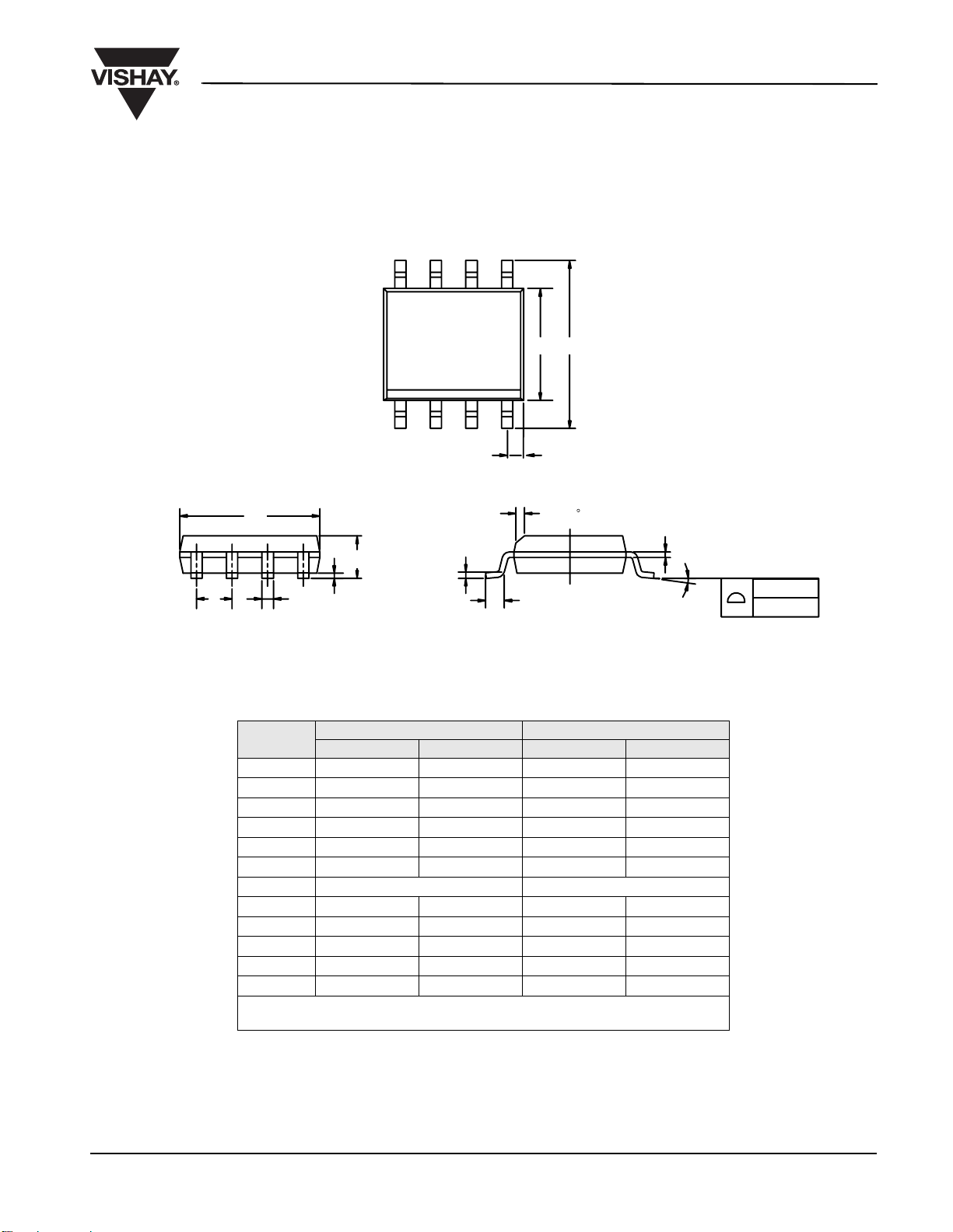
SOIC (NARROW): 8-LEAD
JEDEC Part Number: MS-012
Package Information
Vishay Siliconix
D
e
BA
1
DIM
A 1.35 1.75 0.053 0.069
A
1
B 0.35 0.51 0.014 0.020
C 0.19 0.25 0.0075 0.010
D 4.80 5.00 0.189 0.196
E 3.80 4.00 0.150 0.157
e 1.27 BSC 0.050 BSC
H 5.80 6.20 0.228 0.244
h 0.25 0.50 0.010 0.020
L 0.50 0.93 0.020 0.037
q0°8°0°8°
S 0.44 0.64 0.018 0.026
ECN: C-06527-Rev. I, 11-Sep-06
DWG: 5498
8
1
0.25 mm (Gage Plane)
A
6
7
2
5
HE
3
4
S
h x 45
C
L
MILLIMETERS INCHES
Min Max Min Max
0.10 0.20 0.004 0.008
All Leads
q
0.101 mm
0.004"
Document Number: 71192
11-Sep-06
www.vishay.com
1
Page 8
VISHAY SILICONIX
TrenchFET® Power MOSFETs
Application Note 808
Mounting LITTLE FOOT®, SO-8 Power MOSFETs
Wharton McDaniel
Surface-mounted LITTLE FOOT power MOSFETs use
integrated circuit and small-signal packages which have
been been modified to provide the heat transfer capabilities
required by power devices. Leadframe materials and
0.050
1.27
design, molding compounds, and die attach materials have
been changed, while the footprint of the packages remains
the same.
See Application Note 826, Recommended Minimum Pad
Patterns With Outline Drawing Access for Vishay Siliconix
MOSFETs, (http://www.vishay.com/ppg?72286), for the
0.027
0.69
0.07
1.98
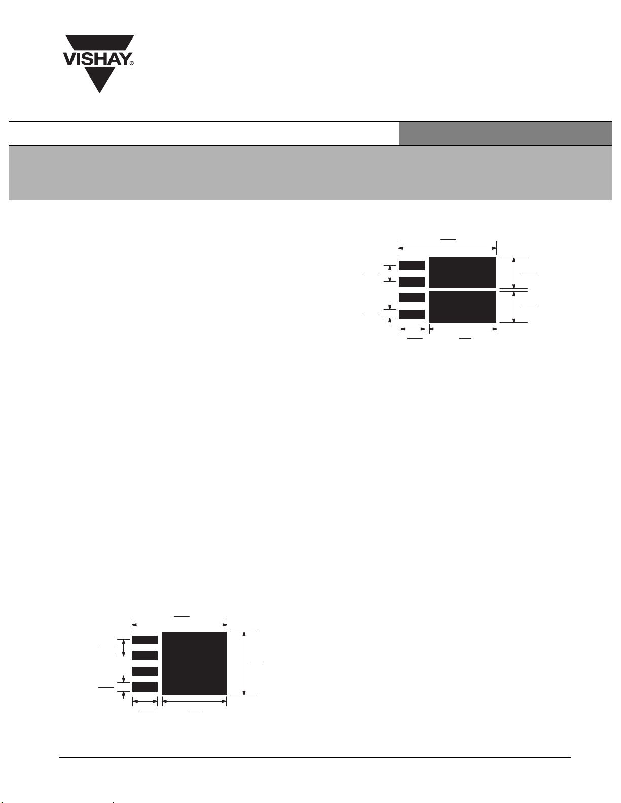
Figure 2. Dual MOSFET SO-8 Pad Pattern
basis of the pad design for a LITTLE FOOT SO-8 power
MOSFET. In converting this recommended minimum pad
to the pad set for a power MOSFET, designers must make
two connections: an electrical connection and a thermal
connection, to draw heat away from the package.
In the case of the SO-8 package, the thermal connections
are very simple. Pins 5, 6, 7, and 8 are the drain of the
MOSFET for a single MOSFET package and are connected
together. In a dual package, pins 5 and 6 are one drain, and
pins 7 and 8 are the other drain. For a small-signal device or
integrated circuit, typical connections would be made with
traces that are 0.020 inches wide. Since the drain pins serve
the additional function of providing the thermal connection
to the package, this level of connection is inadequate. The
The minimum recommended pad patterns for the
single-MOSFET SO-8 with copper spreading (Figure 1) and
dual-MOSFET SO-8 with copper spreading (Figure 2) show
the starting point for utilizing the board area available for the
heat-spreading copper. To create this pattern, a plane of
copper overlies the drain pins. The copper plane connects
the drain pins electrically, but more importantly provides
planar copper to draw heat from the drain leads and start the
process of spreading the heat so it can be dissipated into the
ambient air. These patterns use all the available area
underneath the body for this purpose.
total cross section of the copper may be adequate to carry
the current required for the application, but it presents a
large thermal impedance. Also, heat spreads in a circular
fashion from the heat source. In this case the drain pins are
the heat sources when looking at heat spread on the PC
board.
Since surface-mounted packages are small, and reflow
soldering is the most common way in which these are
affixed to the PC board, “thermal” connections from the
planar copper to the pads have not been used. Even if
additional planar copper area is used, there should be no
problems in the soldering process. The actual solder
0.288
7.3
connections are defined by the solder mask openings. By
combining the basic footprint with the copper plane on the
0.050
1.27
0.027
0.69
0.078
1.98
0.2
5.07
0.196
5.0
Figure 1. Single MOSFET SO-8 Pad
Pattern With Copper Spreading
Document Number: 70740 www.vishay.com
Revision: 18-Jun-07 1
drain pins, the solder mask generation occurs automatically.
A final item to keep in mind is the width of the power traces.
The absolute minimum power trace width must be
determined by the amount of current it has to carry. For
thermal reasons, this minimum width should be at least
0.020 inches. The use of wide traces connected to the drain
plane provides a low impedance path for heat to move away
from the device.
0.288
7.3
8
0.2
5.07
With Copper Spreading
0.088
2.25
0.088
2.25
APPLICATION NOTE
Page 9
Application Note 826
Vishay Siliconix
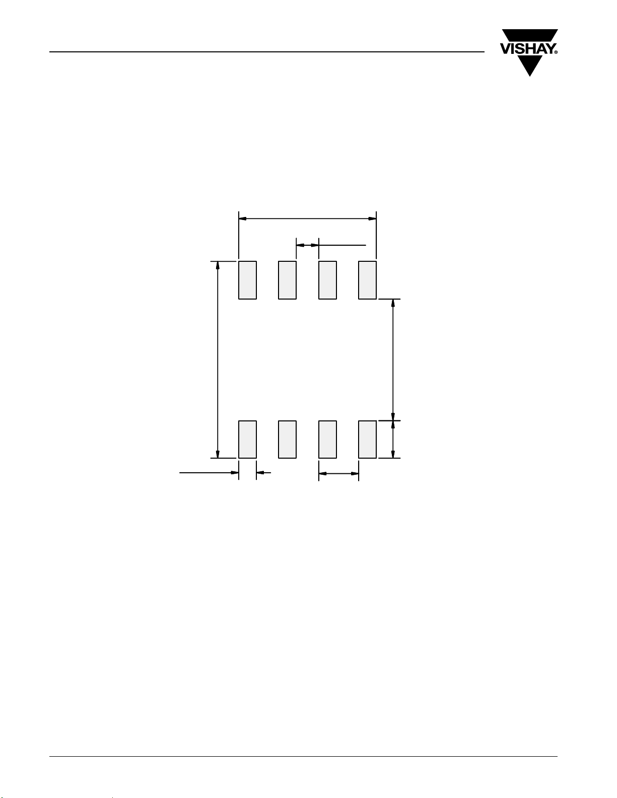
RECOMMENDED MINIMUM PADS FOR SO-8
0.172
(4.369)
0.028
(0.711)
Return to Index
Return to Index
0.022
(0.559)
0.246
(6.248)
Recommended Minimum Pads
Dimensions in Inches/(mm)
0.050
(1.270)
0.152
0.047
(3.861)
(1.194)
APPLICATION NOTE
www.vishay.com Document Number: 72606
22 Revision: 21-Jan-08
Page 10

Legal Disclaimer Notice
Vishay
Disclaimer
ALL PRODUCT, PRODUCT SPECIFICATIONS AND DATA ARE SUBJECT TO CHANGE WITHOUT NOTICE TO IMPROVE
RELIABILITY, FUNCTION OR DESIGN OR OTHERWISE.
Vishay Intertechnology, Inc., its affiliates, agents, and employees, and all persons acting on its or their behalf (collectively,
“Vishay”), disclaim any and all liability for any errors, inaccuracies or incompleteness contained in any datasheet or in any other
disclosure relating to any product.
Vishay makes no warranty, representation or guarantee regarding the suitability of the products for any particular purpose or
the continuing production of any product. To the maximum extent permitted by applicable law, Vishay disclaims (i) any and all
liability arising out of the application or use of any product, (ii) any and all liability, including without limitation special,
consequential or incidental damages, and (iii) any and all implied warranties, including warranties of fitness for particular
purpose, non-infringement and merchantability.
Statements regarding the suitability of products for certain types of applications are based on Vishay’s knowledge of typical
requirements that are often placed on Vishay products in generic applications. Such statements are not binding statements
about the suitability of products for a particular application. It is the customer’s responsibility to validate that a particular
product with the properties described in the product specification is suitable for use in a particular application. Parameters
provided in datasheets and/or specifications may vary in different applications and performance may vary over time. All
operating parameters, including typical parameters, must be validated for each customer application by the customer’s
technical experts. Product specifications do not expand or otherwise modify Vishay’s terms and conditions of purchase,
including but not limited to the warranty expressed therein.
Except as expressly indicated in writing, Vishay products are not designed for use in medical, life-saving, or life-sustaining
applications or for any other application in which the failure of the Vishay product could result in personal injury or death.
Customers using or selling Vishay products not expressly indicated for use in such applications do so at their own risk and agree
to fully indemnify and hold Vishay and its distributors harmless from and against any and all claims, liabilities, expenses and
damages arising or resulting in connection with such use or sale, including attorneys fees, even if such claim alleges that Vishay
or its distributor was negligent regarding the design or manufacture of the part. Please contact authorized Vishay personnel to
obtain written terms and conditions regarding products designed for such applications.
No license, express or implied, by estoppel or otherwise, to any intellectual property rights is granted by this document or by
any conduct of Vishay. Product names and markings noted herein may be trademarks of their respective owners.
Document Number: 91000 www.vishay.com
Revision: 11-Mar-11 1
 Loading...