

Page 1
Ultraviolet Selective Sensor SFH 530
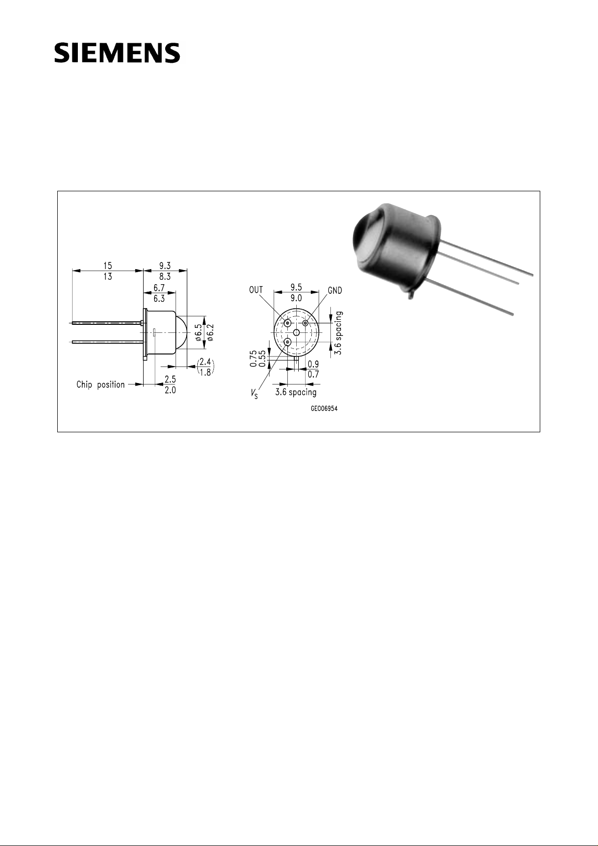
Maße in mm, wenn nicht anders angegeben/Dimensions in mm, unless otherwise specified.
Wesentliche Merkmale
• Hohe UV-Empfindlichkeit
• Speziell geeignet für Anwendungen bei
310 nm
• Geringe Empfindlichkeit bei sichtbarem und
IR-Licht
• Eine Versorgungsspannung
• Geringe Stromaufnahme
• Hermetisch dichte Metallbauform (TO-39)
Anwendungen
• Flammenmelder
• Chem. und biomedizinische Analyse
• Photometrie
• Excimerlasersteuerung und -überwachung
• Umwelt-Kartierung
• Hautbestrahlungsforschung
• Überwachung von UV-Sterilisierungsgeräten
• Medizinische Fehlerdiagnose
• Schweißprozeßüberwachung
Features
• High UV sensitivity
• Suitable esp. for applications at 310 nm
• Low sensitivity for visible and infrared light
• Single supply voltage
• Low current consumption
• Hermetically sealed metal package (TO-39)
Applications
• Flame detector
• Chemical and biomedical analysis
• Photometry
• Excimer laser control and monitoring
• Environment mapping
• Skin irradiation studies
• Monitoring of UV sterilising equipment
• Medical diagnostic
• Welding monitoring
Semiconductor Group 1 1998-08-27
Page 2

SFH 530
Typ
Type
Bestellnummer
Ordering Code
SFH 530 Q62702-P1706
Grenzwerte
Maximum Ratings
Bezeichnung
Description
Betriebs- und Lagertemperatur
Operating and storage temperature range
Versorgungsspannung
Supply voltage
Kennwerte (TA=25 °C)
Characteristics
Bezeichnung
Description
Symbol
Symbol
Top; T
stg
V
S
Symbol
Symbol
Wert
Value
–20…+80 °C
8V
Wert
Value
min. typ. max.
Einheit
Unit
Einheit
Unit
Versorgungsstrom
Supply current
5 V, 20 °C, dark, no load
Max. Ausgangsstrom
Max. output current
5 V, 20 °C, saturation, 1.4 kΩ load
Schwingungsbreite für die Ausgangsspannung
Output swing
5 V, 20 °C, saturation, no load
5 V, 20 °C, dark, no load
PSRR (50 … 100 Hz)
5 V, 20 °C, no load
Offsetspannung
Offset voltage
5 V, 25 °C, no load
5 V, 60 °C, no load
5 V, 80 °C, no load
Halbwinkel
Half angle
NEP at 310 nm
5 V, 20 °C, no load
I
S
I
out
50 65 90 µA
35 51 72 µA
–
2.1
0
2.6
0.2
3.1
1
V
mV
– 40 – 62 dB
V
off
–5
–10
–60
0
–2
–10
1
0
–1
mV
ϕ – ± 7.5 – Grad
Deg.
NEP
–7×10
-14
–W/√Hz
Semiconductor Group 2 1998-08-27
Page 3

Kennwerte (TA=25 °C)
Characteristics (cont’d)
SFH 530
Bezeichnung
Description
Nachweisgrenze, λ = 310 nm
Symbol
Symbol
D
*–5×10
Detection limit
5 V, 20 °C, no load
Aktive Fläche
A
10 11 12 mm
Active area (1)
Empfindlichkeit bei 310 nm
– 135 – – mV
Responsivity at 310 nm
5 V, 20 °C, no load
Selectivity (2)
–––10-4–
5 V, 20 °C, no load
Responsivity to a 2856 K quartz-halogen lamp
– – – 0.5 mV/lx
without UV (glass filter GG400)
5 V, 20 °C, no load
Transimpedanz
– 1.1 1.3 1.5 GΩ
Transimpedance
(1) Aufgrund der Lichtbündelung der Linse.
Due to the light concentration of the lens.
(2) Selektivität = max {Empfindlichkeit von 400 nm bis 1200 nm}
Selectivity = max {Responsivity in the range of 400 … 1200 nm}
_________________________________________________
Empfindlichkeit bei 310 nm
___________________________________________________
Responsivity at 310 nm
Wert
Value
11
Einheit
Unit
– m · √Hz
W
2
nW/mm
2
Fig. 1
Typ. spektr. Verhalten des UV Sensors
Typ. spectr. response of the UV sensor
OHF00262
2
10
mV
nW
1
10
0
10
Responsivity
-1
10
-2
10
-3
10
-4
10
200
400 600 800 1000 nm 1300
Wavelength
2
10
%
1
10
0
10
-1
10
Quantum Efficiency
-2
10
-3
10
-4
10
Fig. 2
Empfangscharakteristik
Response characteristic
1.0
V
out rel
0.9
0.8
0.7
0.6
0.5
0.4
0.3
0.2
0.1
0
-15 -10 -5 0 5 10 15
V
= f(ϕ)
out
OHF00425
)(
ϕ
Semiconductor Group 3 1998-08-27
Page 4

SFH 530
Ultraviolet Selective Sensor
Allgemeines
Der SFH 530, ein ultraviolett (UV)-selektiver optischer Sensor, wurde speziell für die hohen Anforderungen an die Flammenüberwachung in
Ölbrennern (Blaubrenner) entwickelt und ist für
viele weitere anspruchsvolle Meßaufgaben im
Bereich der UV-Detektion einsetzbar. Die Fotodiode und die Verstärkerschaltung (Verstärkung des Fotostromes, Umsetzung in ein Spannungssignal) befinden sich in einem hermetisch
dichten TO-39 Gehäuse mit drei Anschlußpins
(GND, Vs: Betriebsspannung, OUT: Ausgangsspannung). Das Gehäuse bietet besonderen
Schutz vor Störungen durch elektromagnetische Felder und vor Feuchtigkeit über den gesamten Betriebstemperaturbereich von – 20 ˚C
bis + 80 ˚C.
Ultraviolet Selective Sensor
General
The SFH 530, an ultraviolet (UV) selective optical sensor has been specially developed for the
exacting requirements placed on flame monitoring in oil burners and can be used for many other important measuring tasks in the UV detection area. The photodiode and the amplifier circuit (amplification of the photocurrent, conversion to a voltage signal) are housed in a hermetically sealed TO-39 package with three terminal
pins (GND, Vs: operating voltage, OUT: output
voltage). The package is specially protected
against electromagnetic interference and moisture over the entire operating temperature
range of – 20 ˚C to + 80 ˚C.
Optisches Verhalten
Das optische Verhalten des SFH 530 wird
durch die Kombination aus einer UV-durchlässigen Sammellinse, einem UV-Filterglas und einer Si-Fotodiode mit hoher Selektivität für
UV-Strahlung bestimmt. Die Selektivität im Wellenlängenbereich von 290 nm bis 350 nm wird
durch eine definierte Dotierung der Fotodiode
und ein aufgedampftes Interferenzfilter erreicht.
Dadurch wird der Einfluß sichtbarer und infraroter Strahlung auf das Nutzsignal stark unterdrückt. Die Empfindlichkeit für Wellenlängen
≥ 400 nm ist stets kleiner als ein Zehntausendstel der maximalen Empfindlichkeit bei
ca. 310 nm.
Optical Characteristics
The optical behavior of the SFH 530 is determined by the combination of a UV-permeable
focusing lens, a UV filter glass and a Si photodiode with high selectivity for UV radiation. The
selectivity in the wavelength range 290 to
350 nm is achieved by means of a defined doping of the photodiode and a vapor-deposited interference filter. This heavily suppresses the effect of visible and infrared radiation on the signal. The sensitivity to wavelengths ≥ 400 nm is
always less than one ten-thousandth of the
maximum sensitivity at approximately 310 nm.
Semiconductor Group 4 1998-08-27
Page 5

SFH 530
Elektrisches Verhalten
• Betrieb mit nur einer Versorgungsspannung
• Der Fotostrom der UV-Diode liegt typischerweise bei Iph= 100 pA. Für ein hohes Ausgangssignal muß der Rückkopplungswiderstand R1 der Verstärkerschaltung sehr hochohmig typ.1 GΩ sein.
Die wesentlichen elektrischen Funktionen des
UV-Sensors zeigt das Ersatzschaltbild (Bild 3).
Electrical Characteristics
• Operated from a single supply voltage.
• The photocurrent of the UV diode is typically
I
= 100 pA. For a high output signal the val-
ph
ue of the feedback resistor R1 in the amplifier
circuit must be very high typ. 1 GΩ.
The main electrical functions of the UV sensor
are shown in the equivalent circuit diagram
(Figure 3).
Bild 3
•
V
=(Iph-IL) Rk + V
out
(1 + R1/Rd)
off
• Für oszillierende Beleuchtungsstärken stellt
die Schaltung einen Tiefpaß erster Ordnung
mit einer Grenzfrequenz von typisch 100 Hz
dar.
Temperaturverhalten:
I
: ist bei Raumtemperatur typisch < 1 pA
L
und verdoppelt sich alle 12 ˚C
R
: ist bei Raumtemperatur typisch > 10 GΩ,
d
besteht aus der Parallelschaltung der entsprechenden Widerstände des
– Rekombinationsstromes
(verdoppelt sich alle 12 ˚C),
– Diffusionsstromes
Figure 3
•
V
=(Iph-IL) Rk+ V
out
(1 + R1/Rd)
off
• For oscillating illuminances the circuit constitutes a first-order lowpass filter with a cutoff
frequency of typically 100 Hz.
Temperature behavior:
I
: is typically < 1 pA at room temperature
L
and doubles every 12 ˚C
R
: is typically > 10 GΩ (at room temperature,
d
consisting of the parallel connection of the
corresponding resistances of the
– recombination current
(doubles every 12 ˚C),
– diffusion current
(doubles every 5.6 ˚C)
(verdoppelt sich alle 5.6 ˚C)
Semiconductor Group 5 1998-08-27
Page 6

SFH 530
• Das Temperaturverhalten zeigt großen Einfluß auf das Ausgangssignal des Sensors.
Der ASIC ist so ausgelegt, daß er bei Raumtemperatur 0 … – 1 mV Offset und einen negativen Temperaturkoeffizienten aufweist.
Auch auftretende Leckströme würden das
Nutzsignal nur verringern (der Leckstrom ist
stets subtraktiv bezüglich des Ausgangssignals).
• The temperature behavior shows the marked
effect on the sensor’s output signal. The
ASIC is so designed that it exhibits a 0 to
– 1 mV offset and a negative temperature
coefficient at room temperature. Even any
leakage currents present would only reduce
the wanted signal (the leakage current is always subtractive with respect to the output
signal).
Semiconductor Group 6 1998-08-27
 Loading...