

Page 1
SFH 507
IR-Empfänger für Fernbedienungen (für kurze Burst)
IR-Receiver for Remote Control Systems (for Short Burst)
31.1
30.1
16.3
15.9
12.9
12.1
9.7
10.3
1.5
9.7
8.7
0.8 max.
4.45
3.85
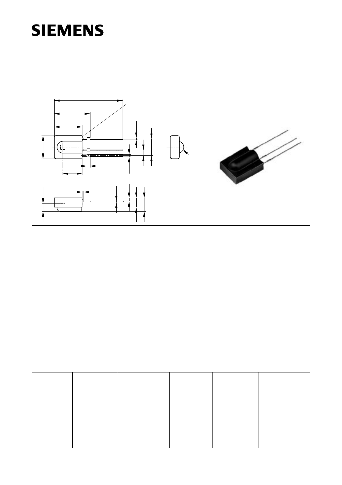
Maße in mm, wenn nicht anders angegeben/Dimensions in mm, unless otherwise specified.
V
V
Wesentliche Merkmale
● Empfängermodul für Übertragungsprotokolle
mit kurzen Pulspaketen (N≥ 6 Pulse pro Bit)
● Fotodiode mit integriertem Verstärker
● Gehäuse schwarz eingefärbt: Verguß optimiert
für eine Wellenlänge von 950 nm
● Hohe Störsicherheit
● Geringe Stromaufnahme (0.5 mA typ.)
● 5 V Betriebsspannung
● Hohe Empfindlichkeit
● TTL und CMOS kompatibel
● Mögliche Datenübertragungsrate 2.4 kbit/s
(N = 6, f0= 56 kHz)
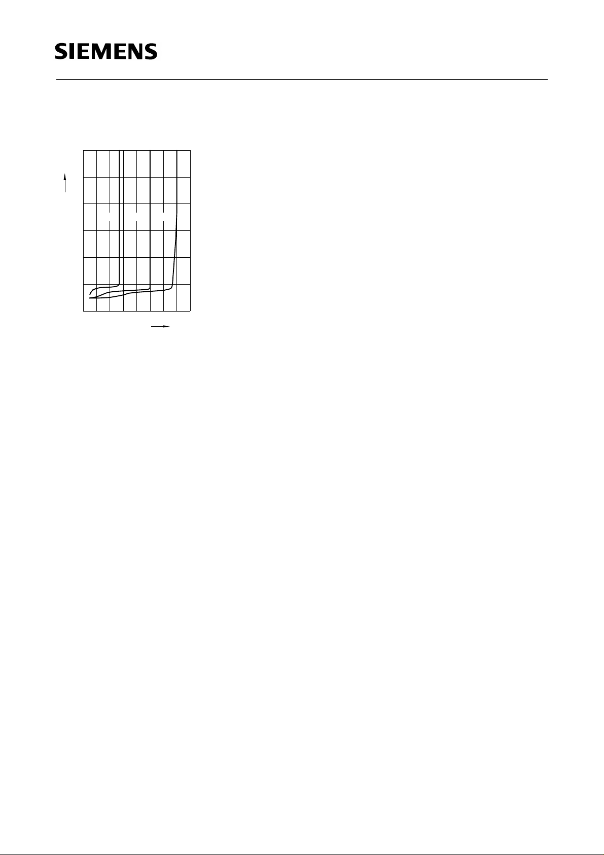
Surface not flat
OUT
S
GND
0.65
1.7
0.4
0.50
0.50
1.1
4.3
6.1
3.7
2.54
5.5
3x2.54 = 7.62
R 2.75
GEX06910
Features
● Receiver module for transmission codes
with short bursts (N≥ 6 pulses per bit)
● Photodiode with hybride integrated circuit
● Black epoxy resin: daylight filter optimized
for 950 nm
● High immunity against ambient light
● Low power consumption (0.5 mA typ.)
● 5 V supply voltage
● High sensitivity (internal shield case)
● TTL and CMOS compatibility
● 2.4 kbit/s data transmission possible
(N = 6, f0= 56 kHz)
SFH 507
fex06841
Anwendungen
● Empfänger für IR-Fernsteuerungen
Typ
Type
Trägerfrequ.
Carrier
Bestellnr.
Ordering Code
Frequency
kHz
Applications
● IR-remote control preamplifier module
Typ
Type
Trägerfrequ.
Carrier
Bestellnr.
Ordering Code
Frequency
kHz
SFH 507-30 30 Q62702-P1701 SFH 507-38 38 Q62702-P1704
SFH 507-33 33 Q62702-P1702 SFH 507-40 40 Q62702-P1705
SFH 507-36 36 Q62702-P1703 SFH 507-56 56 Q62702-P1822
Semiconductor Group 1
05.97
Page 2
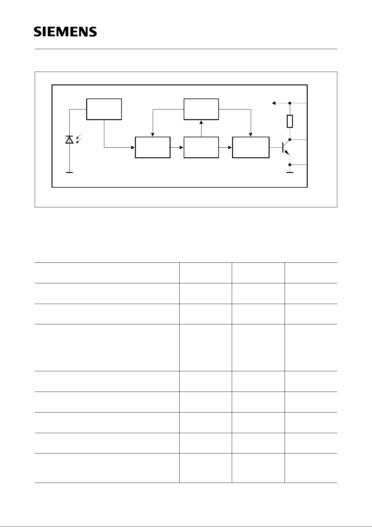
PIN
Input
AGC
Control
Circuit
Bandpass
Demodulator
100 kΩ
SFH 507
2
3
1
OHF02198
V
S
OUT
GND
Blockschaltbild
Block Diagram
Grenzwerte (TA = 25°C)
Maximum Ratings
Bezeichnung
Description
Betriebs- und Lagertemperatur
Operation and storage temperature range
Sperrschichttemperatur
Junction temperature range
Löttemperatur
Lötstelle 1 mm vom Gehäuse; Lötzeit
t ≤ 10 s
Soldering temperature
soldering joint ≥ 1 mm distance from
package, soldering time t ≤10 s
Betriebsspannung Pin 2
Supply voltage
Symbol
Symbol
T
, T
A
stg
T
j
T
S
V
S
Wert
Value
Einheit
Unit
– 25 ... + 85 °C
100 °C
260 °C
– 0.3 ... + 6.0 V
Betriebsstrom Pin 2
I
Supply current
Ausgangsspannung Pin 3
V
Output voltage
Ausgangsstrom Pin 3
I
Output current
Verlustleistung
P
Total power dissipation
T
≤ 85 °C
A
Semiconductor Group 2
CC
OUT
OUT
tot
5mA
– 0.3 ... + 6.0 V
5mA
50 mW
Page 3

Kennwerte (TA = 25 °C)
Characteristics
SFH 507
Bezeichnung
Description
Betriebsspannung
Supply voltage
Bestrahlungsstärke (Testsignal, s. Figure 2)
Threshold irradiance (test signal, see Fig. 2)
Wellenlänge der max. Fotoempfindlichkeit
Symbol
Symbol
V
S
E
e min(30-40 kHz)
E
e min(56 kHZ)
1)
E
e max
λ
s max
Wert
Value
typ. 5.0
Einheit
Unit
V
(4.5 ... 5.5)
1)
1)
typ. 0.4 (< 0.6)
typ. 0.45 (< 0.7)
30
mW/m
mW/m
W/m
950 nm
Wavelength of max. sensitivity
Halbwinkel
ϕ±45 deg.
Half angle
Stromaufnahme Pin 2
Current consumption
V
= 5 V, Ev = 0
s
V
= 5 V, Ev = 40 kIx, sunlight
s
Ausgangsspannung Pin 3
I
CC
I
CC
V
OUT low
0.5 (< 0.8)
1.0
mA
mA
≤ 250 mV
Output voltage
I
= 0.5 mA, Ee = 0.7 mW/m
OUT
2
(Testsignal, s. Figure 2)
(test signal, see Fig. 2)
1)
In Verbindung mit einer typ. SFH 415 bei Betrieb mit IF= 0.5 A wird eine Reichweite von ca. 35 m erreicht.
1)
Together with an IRED SFH 415 under operation conditions of IF= 0.5 A a distance of 35 m is possible.
2
2
2
Semiconductor Group 3
Page 4
SFH
506/507
SFH 507
*)
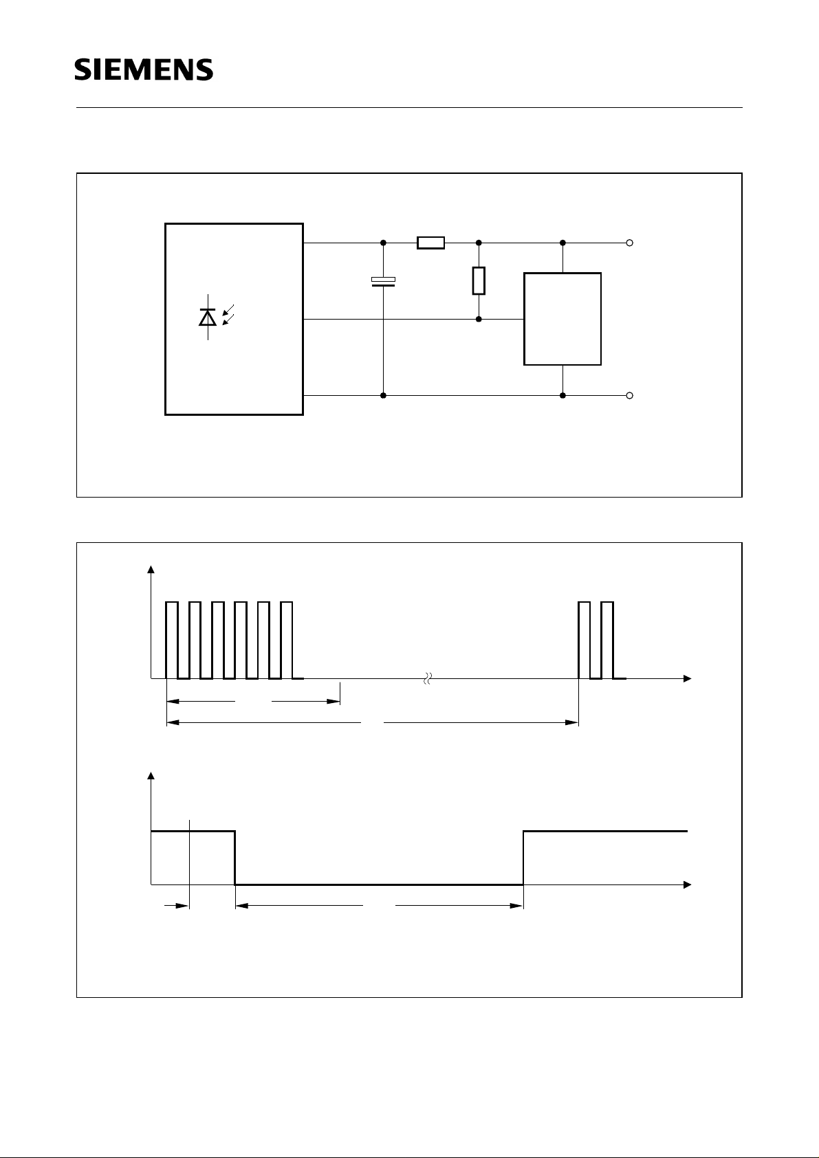
330 Ω
2
*)
µ
F
4.7
3
>10 kΩ
optional
µ
C
+5V
*)
only necessary to suppress power supply disturbances
Figure 1 Externe Beschaltung
External circuit
E
e
*)
t
pi
V
O
1
GND
OHF02197
t
T
*)
_
<
N
6 Pulses is recommended for optimal function
V
OH
V
OL
1)
2)
t
t
<4/
f
o
3/ <
pi-o
t
d
<
10/
d
f
t
po
f
o
<6/
+
t
pi
f
o
2)1)
t
po
t
OHF00220
Figure 2 Optisches Testsignal (IR-Diode SFH 415, IF = 0.5 A, N = 6 pulses, f = f0, T = 10 ms)
Optical test signal
Semiconductor Group 4
Page 5
SFH 507
Sensitivity vs. electric field disturbance
E
= f (E), field strength of disturbance,
e min
f = f
0
1.0
mW/m
E
e min
0.8
2
(E) =
OHF00217
ff
0
0.6
0.4
(E) = 10 kHz
f
0.2
0
0
0.4 0.8 1.2 kV/m 2.0
E
Relative luminous sensitivity
S
= f (λ), TA = 25oC
rel
1.0
S
rel
0.8
OHF02193
Vertical directivity ϕ
y
-10 0
ϕ
-20
1.6
1.4
1.2
-30
1.0
0.8
-40
-50
0.6
0.4
-60
-70
0.2
-80
-90
0 0.6
-0.2-0.4-0.6 0.2 0.4
Horizontal directivity ϕ
-10 0
ϕ
-20
1.6
1.4
1.2
Sensitivity vs. bright ambient
E
= f (E)
e min
10
OHF00246
20
2
10
Correlation with ambient light sources
2
mW/m
(disturbance effect) : 10 W/m
E
e min
(daylight, T = 5900 K)
1
10
30
40
0
50
10
60
70
80
90
x
10
OHF00247
20
-1
10
-2
10 10
Sensitivity vs. supply volt. disturbances,
E
= f (∆V
e min
1
10
2
mW/m
E
e min
Ambient, = 950 nmλ
-1 0
S RMS
f0f
=
10110
)
OHF00215
2
_
_
~
1.4 klx
_
_
~
8.2 klx(stand. illum. A, T= 2855 K)
W/m
E
OHF00214
10 kHz 1 kHz
2
2
10
0.6
0.4
0.2
0.0
800λ850 900 950 1000 1050 nm 1150
Output pulse
T
, T
= f(Ee)
on
off
1.0
ms
T
T
on,
off
0.8
0.6
0.4
= 950 nmλ
0.2
-30
1.0
0.8
-40
-50
-60
-70
0.6
0.4
0.2
-80
OHF00245
-90
Relative sensitivity E
f = f
± 5 %, ∆f (3 dB) = f0/7
0
1.0
E
E
e min/e
0 0.6
-0.2-0.4-0.6 0.2 0.4
/
Ee= f (f / f0)
e min
0.8
T
on
OHF00219
30
0
10
40
50
60
100 Hz
70
80
90
-1
10
-1
-2
10
0
10
10 10
2
1
10
3
mV
10
V
∆
s RMS
Sensitivity vs. dark ambient
T
= f (Ee)
T
p out
p out
300
250
s
µ
OHF00216
200
0.6
Input burst duration
T
off
150
0.4
100
0.2
50
λ= 950 nm
0.0
-1
012 4
10 10 10
2
mW/m10
10
E
e
0
0.7
0.8 0.9 1.0 1.1 1.2 1.3
Semiconductor Group 5
0
-1
10 mW/m
f
/
f
0
10010110
2
4
2
10
E
e
Page 6
Sensitivity vs. duty cycle
= f (tp / T)
E
e
3.0
2
mW/m
E
e min
2.5
2.0
N
= 6 = 16
N
1.5
0.1
0.5
0.0
0.0
0.2 0.4 0.6 0.8
N
= 32
OHL00218
t
/T
p
SFH 507
Semiconductor Group 6
 Loading...