

Page 1
GaAIAs-IR-Lumineszenzdiode (880 nm)
GaAIAs Infrared Emitter (880 nm)
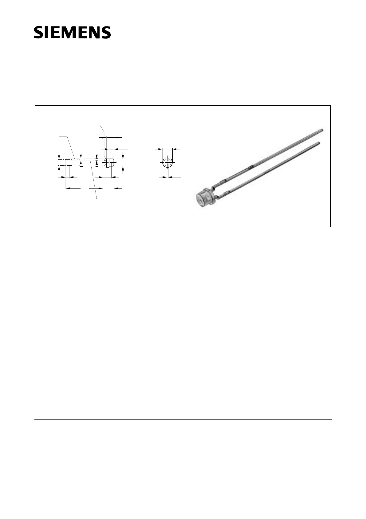
SFH 487 P
Area not flat
0.6
0.4
spacing
2.54 mm
Approx. weight 0.3 g
Maβe in mm, wenn nicht anders angegeben/Dimensions in mm, unless otherwise specified.
1.8
1.2
0.7
29
27
0.4
Wesentliche Merkmale
● GaAIAs-IR-Lumineszenzdiode, hergestellt
im Schmelzepitaxieverfahren
● Hohe Zuverlässigkeit
● Enge Toleranz: Chipoberfläche/
Bauteiloberkante
● Hohe Impulsbelastbarkeit
● Gute spektrale Anpassung an
Si-Fotoempfänger
● Sehr plane Oberfläche
● Gehäusegleich mit SFH 309
0.8
0.4
4.5
4.0
Cathode
3.1
2.5
2.0
1.7
3.5
Chip position
ø3.1
ø2.9
4.0
3.6
0.6
0.4
GEX06308
Features
● GaAIAs infrared emitting diode, fabricated in
a liquid phase epitaxy process
● High reliability
● Small tolerance: Chip surface to case
surface
● High pulse handling capability
● Good spectral match to silicon
photodetectors
● Plane surface
● Same package as SFH 309
fex06308
Anwendungen
● Lichtschranken für Gleich- und
Wechsellichtbetrieb bis 500 kHz
● LWL
Typ
Type
Bestellnummer
Ordering Code
Gehäuse
Package
Applications
● Photointerrupters
● Fibre optic transmission
SFH 487 P Q62703-Q517 3-mm-LED-Gehäuse, plan, klares violettes Epoxy-
Gieβharz, Anschlüsse im 2.54-mm-Raster (
1
/10’’),
Anodenkennzeichnung: kürzerer Anschluβ
3 mm LED package (T 1), plane, violet-colored transparent epoxy resin, solder tabs lead spacing 2.54 mm
(1/10’’), anode marking: short lead
Semiconductor Group 1 1997-11-01
Page 2
Grenzwerte (TA = 25 °C)
Maximum Ratings
SFH 487 P
Bezeichnung
Description
Betriebs- und Lagertemperatur
Operating and storage temperature range
Sperrschichttemperatur
Junction temperature
Sperrspannung
Reverse voltage
Durchlaβstrom
Forward current
Stoβstrom, τ≤10 µs
Surge current
Verlustleistung
Power dissipation
Wärmewiderstand, freie Beinchenlänge
max. 10 mm
Thermal resistance, lead length between
package bottom and PC-board max. 10 mm
Symbol
Symbol
T
; T
op
stg
T
j
V
R
I
F
I
FSM
P
tot
R
thJA
Wert
Value
Einheit
Unit
– 55 ... + 100 °C
100 °C
5V
100 mA
2.5 A
200 mW
375 K/W
Kennwerte (
T
= 25 °C)
A
Characteristics
Bezeichnung
Description
Wellenlänge der Strahlung
Wavelength at peak emission
I
= 100 mA
F
Spektrale Bandbreite bei 50 % von
I
= 100 mA
F
Spectral bandwidth at 50 % of I
I
max
Abstrahlwinkel
Half angle
Aktive Chipfläche
Active chip area
Abmessungen der aktiven Chipfläche
Dimension of the active chip area
max
Symbol
Symbol
λ
peak
,
∆λ 80 nm
Wert
Value
Einheit
Unit
880 nm
ϕ±65 Grad
deg.
A
L × B
L
× W
0.16 mm
0.4 × 0.4 mm
2
Semiconductor Group 2 1997-11-01
Page 3

SFH 487 P
Kennwerte (
T
= 25 °C)
A
Characteristics
Bezeichnung
Description
Abstand Chipoberfläche bis
Gehäusevorderseite
Distance chip front to case surface
Schaltzeiten, I
von 10 % auf 90 % und von
e
90 % auf 10 %, bei IF = 100 mA, RL = 50 Ω
Switching times, Ie from 10 % to 90 % and
from 90 % to 10 %, IF = 100 mA, RL = 50 Ω
Kapazität
Capacitance
V
= 0 V, f = 1 MHz
R
Durchlaβspannung
Forward voltage
I
= 100 mA, tp = 20 ms
F
I
= 1 A, tp = 100 µs
F
Sperrstrom
Reverse current
V
= 5 V
R
Gesamtstrahlungsfluβ
Total radiant flux
I
= 100 mA, tp = 20 ms
F
Temperaturkoeffizient von I
I
= 100 mA
F
bzw. Φe,
e
Temperature coefficient or Ie or Φe,
I
= 100 mA
F
Temperaturkoeffizient von
V
, IF = 100 mA
F
Temperature coefficient of VF, IF = 100 mA
Symbol
Symbol
H
t
, t
r
f
C
o
V
F
I
R
Φ
e
TC
I
TC
V
Wert
Value
Einheit
Unit
0.4 ... 0.8 mm
0.6/0.5 µs
25 pF
1.5 (< 1.8)
V
3.0 (< 3.8)
0.01 (≤ 1)µA
25 mW
– 0.5 %/K
– 2 mV/K
Temperaturkoeffizient von λ
Temperature coefficient of λ
, IF = 100 mA
peak
, IF = 100 mA
peak
TC
λ
0.25 nm/K
Semiconductor Group 3 1997-11-01
Page 4

Strahlstärke Ie in Achsrichtung
gemessen bei einem Raumwinkel Ω = 0.01 sr
Grouping of radiant intensity Ie in axial direction
at a solid angle of Ω = 0.01 sr
SFH 487 P
Bezeichnung
Description
Strahlstärke
Radiant intensity
I
= 100 mA, tp = 20 ms I
F
Strahlstärke
Radiant intensity
I
= 1 A, tp = 100 µs I
F
Radiation characteristics I
50
60
70
rel
= f (ϕ)
10203040
ϕ
0
1.0
0.8
0.6
0.4
Symbol Wert
Value
e
e typ.
> 2 mW/sr
30 mW/sr
OHR01894
Einheit
Unit
80
90
100
0.2
0
02040 60 80 100 1200.40.60.81.0
Semiconductor Group 4 1997-11-01
Page 5

Relative spectral emission
I
= f (λ)
rel
100
%
Ι
rel
80
60
40
20
0
750
800 850 900 950 nm 1000
OHR00877
λ
Radiant intensity
t
Single pulse,
10
Ι
e
Ι
(100mA)
e
10
10
-1
10
-2
10
-3
10
= 20 µs
p
2
1
0
0
10 10110
I
e
Ie100 mA
2
= f (IF)
OHR00878
3
10
Ι
SFH 487 P
Max. permissible forward current
I
= f (TA)
F
125
Ι
mA
F
100
75
50
25
0
104mA
F
0 20 40 60 80 100˚C
OHR00880
T
t
= 20 µs
p
= f (VF)
F
Forward current, I
Single pulse,
1
10
A
Ι
F
0
10
-1
10
-2
10
-3
10
0123456V8
OHR00881
V
F
Permissible pulse handling capability
I
= f (τ), TA = 25oC,
F
duty cycle D = parameter
Ι
F
OHR00886
t
p
4
10
mA
0.1
0.005=
D
0.01
0.02
0.05
Ι
F
3
10
0.2
0.5
DC
2
10
t
p
t
p
D
=
T
1
10
-5
10 s
10-410-310-210-110010110
T
Forward current versus lead length
between the package bottom and the
2
PC-board I
120
mA
Ι
100
F
80
60
40
20
= f (I), TA = 25oC
F
0
0 5 10 15 20 25 mm 30
OHR00949
Semiconductor Group 5 1997-11-01
 Loading...