

Page 1
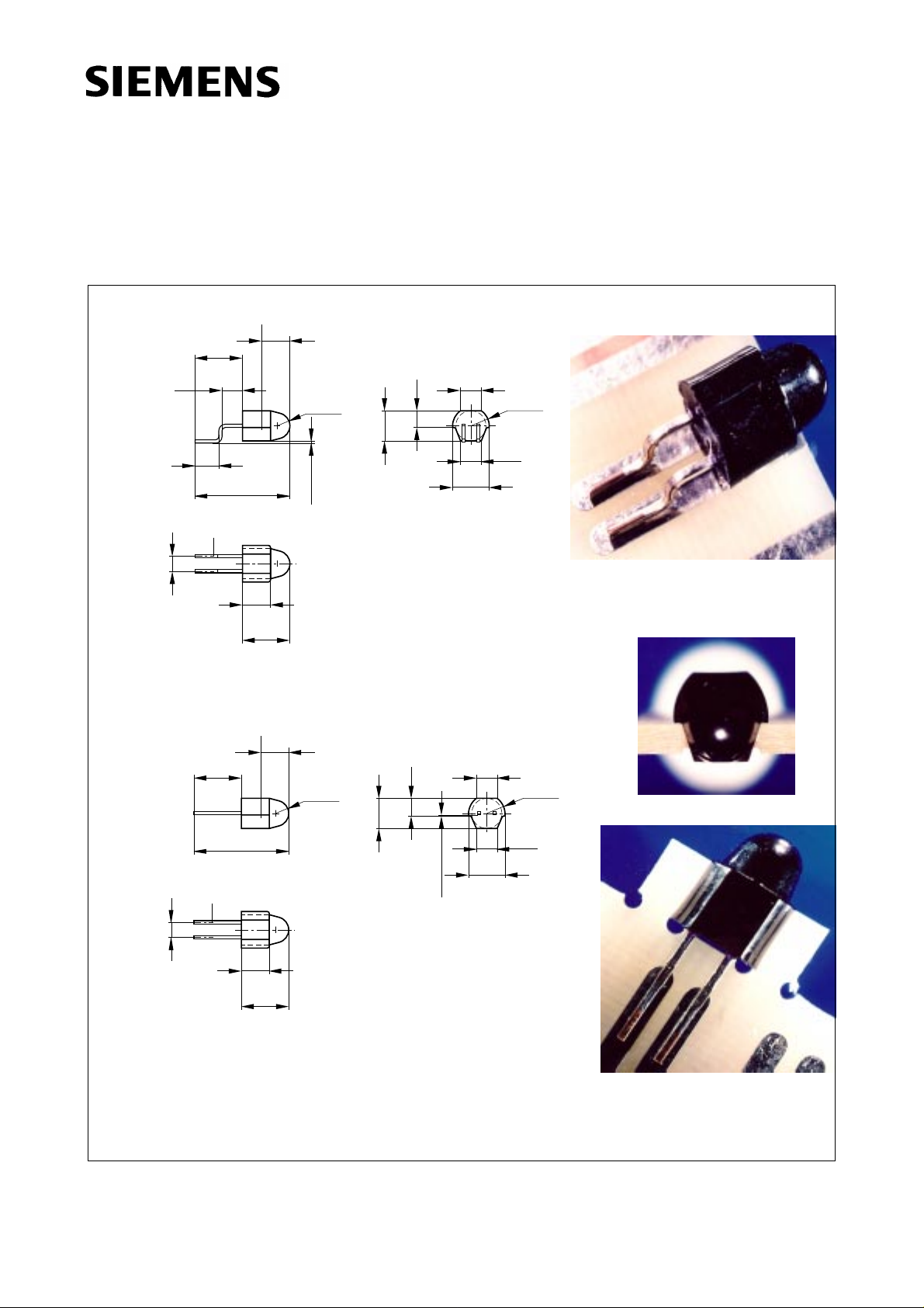
GaAIAs-IR-Lumineszenzdioden (880 nm)
GaAIAs Infrared Emitters (880 nm)
Chip position
4.5
2.7
2.3
Cathode
spacing
2.54 mm
7.5
5.5
3.7
3.3
14.7
13.1
4.5
3.9
3.9
7.7
7.1
2.05
R
1.95
-0.1...0.1
4.8
4.4
2.7
(3.2)
2.4
6.0
5.4
SFH 4580
SFH 4585
(R2.8)
(3.2)
GEO06960
Chip position
4.5
15.5
14.7
4.5
3.9
3.9
7.7
7.1
R
2.05
1.95
4.8
4.4
2.7
2.4
8.0
7.4
Cathode
spacing
2.54 mm
Maße in mm, wenn nicht anders angegeben/Dimensions in mm, unless otherwise specified.
(3.2)
(3.2)
6.0
5.4
-0.15...0..15
(R2.8)
GEO06961
Semiconductor Group 1 1998-11-12
Page 2
SFH 4580
W
●
●
●
●
●
●
A
●
●
s
SFH 4585
esentliche Merkmale
Hergestellt im Schmelzepitaxieverfahren
Für Oberflächenmontage geeignet
Gegurtet lieferbar
Gehäusegleich mit Fotodiode SFH 2500/
SFH 2505
Hohe Zuverlässigkeit
Gute spektrale Anpassung an
Si-Fotoempfänger
nwendungen
IR-Fernsteuerung von Fernseh- und
Rundfunkgeräten, Videorecordern,
Lichtdimmern
Gerätefernsteuerungen für Gleich- und
Wechsellichtbetrieb
Typ
Type
Bestellnummer
Ordering Code
Features
● Fabricated in a liquid phase epitaxy proces
● Suitable for surface mounting (SMT)
● Available on tape and reel
● Same package as photodiode SFH 2500/
SFH 2505
● High reliability
● Spectral match with silicon photodetectors
Applications
● IR remote control of hi-fi and TV-sets, video
tape recorders, dimmers
● Remote control for steady and varying
intensity
Gehäuse
Package
SFH 4580 on request 5-mm-LED-Gehäuse (T 13/4), klares violettes EpoxySFH 4585 on request
Gießharz, Anschlüsse (SFH 4580 gebogen, SFH 4585
gerade) im 2.54-mm-Raster (1/10’’),Kathodenkennzeichnung: siehe Maßzeichnung.
5 mm LED package (T 13/4), violet-colored epoxy resin, solder tabs (SFH 4580 bent, SFH 4585 straight)
lead spacing 2.54 mm (1/10’’), cathode marking: see
package outline.
Semiconductor Group 2 1998-11-12
Page 3

Grenzwerte (TA = 25 °C)
Maximum Ratings
SFH 4580
SFH 4585
Bezeichnung
Description
Betriebs- und Lagertemperatur
Operating and storage temperature range
Sperrschichttemperatur
Junction temperature
Sperrspannung
Reverse voltage
Durchlaßstrom
Forward current
Stoßstrom, tp = 10 µs, D = 0
Surge current
Verlustleistung
Power dissipation
Wärmewiderstand, freie Beinchenlänge
max. 10 mm
Thermal resistance, lead length between
package bottom and PC-board max. 10 mm
Symbol
Symbol
T
; T
op
stg
T
j
V
R
I
F
I
FSM
P
tot
R
thJA
Wert
Value
Einheit
Unit
– 55 ... + 100 °C
100 °C
5V
100 mA
2.5 A
200 mW
375 K/W
Semiconductor Group 3 1998-11-12
Page 4

Kennwerte (TA = 25 °C)
Characteristics
SFH 4580
SFH 4585
Bezeichnung
Description
Wellenlänge der Strahlung
Wavelength at peak emission
I
= 100 mA
F
Spektrale Bandbreite bei 50 % von I
Spectral bandwidth at 50 % of I
I
= 100 m A
F
rel
rel
Abstrahlwinkel
Half angle
Aktive Chipfläche
Active chip area
Abmessungen der aktive Chipfläche
Dimension of the active chip area
Abstand Chipoberfläche bis Linsenscheitel
Distance chip front to lens top
Schaltzeiten, Ie von 10 % auf 90 % und von
90 % auf 10 %, bei IF = 100 mA, RL = 50 Ω
Switching times, Ie from 10 % to 90 % and
from 90 % to10 %, IF = 100 mA, RL = 50 Ω
Symbol
Symbol
λ
peak
Wert
Value
Einheit
Unit
880 nm
∆λ 80 nm
ϕ±15 Grad
deg.
A
L × B
× W
L
0.16 mm
0.4 × 0.4 mm
H 4.2 ... 4.8 mm
t
, t
r
f
0.6/0.5 µs
2
Kapazität
Capacitance
V
= 0 V, f = 1 MHz
R
Durchlaßspannung
Forward voltage
I
= 100 mA, tp = 20 ms
F
I
= 1 A, tp = 100 µs
F
Sperrstrom
Reverse current
V
= 5 V
R
Gesamtstrahlungsfluß
Total radiant flux
I
= 100 mA, tp = 20 ms
F
Temperaturkoeffizient von Ie bzw. Φe,
I
= 100 mA
F
Temperature coefficient of Ie or Φe,
I
= 100 mA
F
Temperaturkoeffizient von VF, IF = 100 mA
Temperature coefficient of VF, IF = 100 mA
C
V
V
I
R
Φ
TC
TC
o
F
F
25 pF
1.50 (≤ 1.8)
3.00 (≤ 3.8)
V
V
0.01 (≤ 1)µA
e
I
V
25 mW
– 0.5 %/K
– 2 mV/K
Semiconductor Group 4 1998-11-12
Page 5

Kennwerte (TA = 25 °C)
Characteristics
SFH 4580
SFH 4585
Bezeichnung
Description
Temperaturkoeffizient von λ, IF = 100 mA
Temperature coefficient of λ, IF = 100 mA
Strahlstärke
Radiant intensity
I
= 100 mA, tp = 20 ms I
F
Strahlstärke
Radiant intensity
I
= 1 A, tp = 100 µs I
F
Radiation characteristics I
50
60
rel
= f (ϕ)
ϕ
10203040
0
1.0
0.8
0.6
Symbol
Symbol
TC
λ
e min
e typ
OHF00300
Wert
Value
Einheit
Unit
0.25 nm/K
≥ 25 mW/sr
225 mW/sr
70
80
90
100
0.4
0.2
0
02040 60 80 100 1200.40.60.81.0
Semiconductor Group 5 1998-11-12
Page 6

Relative spectral emission
I
= f (λ)
rel
100
%
Ι
rel
80
OHR00877
Radiant intensity
Ie100 mA
Single pulse, tp = 20 µs
2
10
Ι
e
Ι
(100mA)
e
1
10
SFH 4580
SFH 4585
I
e
= f (IF)
OHR00878
Max. permissible forward current
I
= f (TA)
F
125
Ι
mA
F
100
OHR00880
60
40
20
0
750
800 850 900 950 nm 1000
Forward current
I
= f (VF), single pulse, tp = 20 µs
F
1
10
A
Ι
F
0
10
-1
10
-2
10
-3
10
0123456V8
λ
OHR00881
V
F
0
10
-1
10
-2
10
-3
10
0
10 10110
2
3
104mA
10
Ι
F
Permissible pulse handling capability
IF= f (τ), TA = 25 °C,
duty cycle D = parameter
Ι
F
OHR00886
t
p
2
4
10
mA
Ι
F
D
0.005=
0.01
0.02
3
10
0.05
0.1
0.2
0.5
DC
2
10
t
p
t
p
D
=
T
1
10
-5
10 s
10-410-310-210-110010110
T
75
50
25
0
0 20 40 60 80 100˚C
T
Forward current versus lead length
between the package bottom and the
PC-board I
120
mA
Ι
100
F
= f (I), TA = 25 °C
F
OHR00949
80
60
40
20
0
0 5 10 15 20 25 mm 30
Semiconductor Group 6 1998-11-12
 Loading...