

Page 1
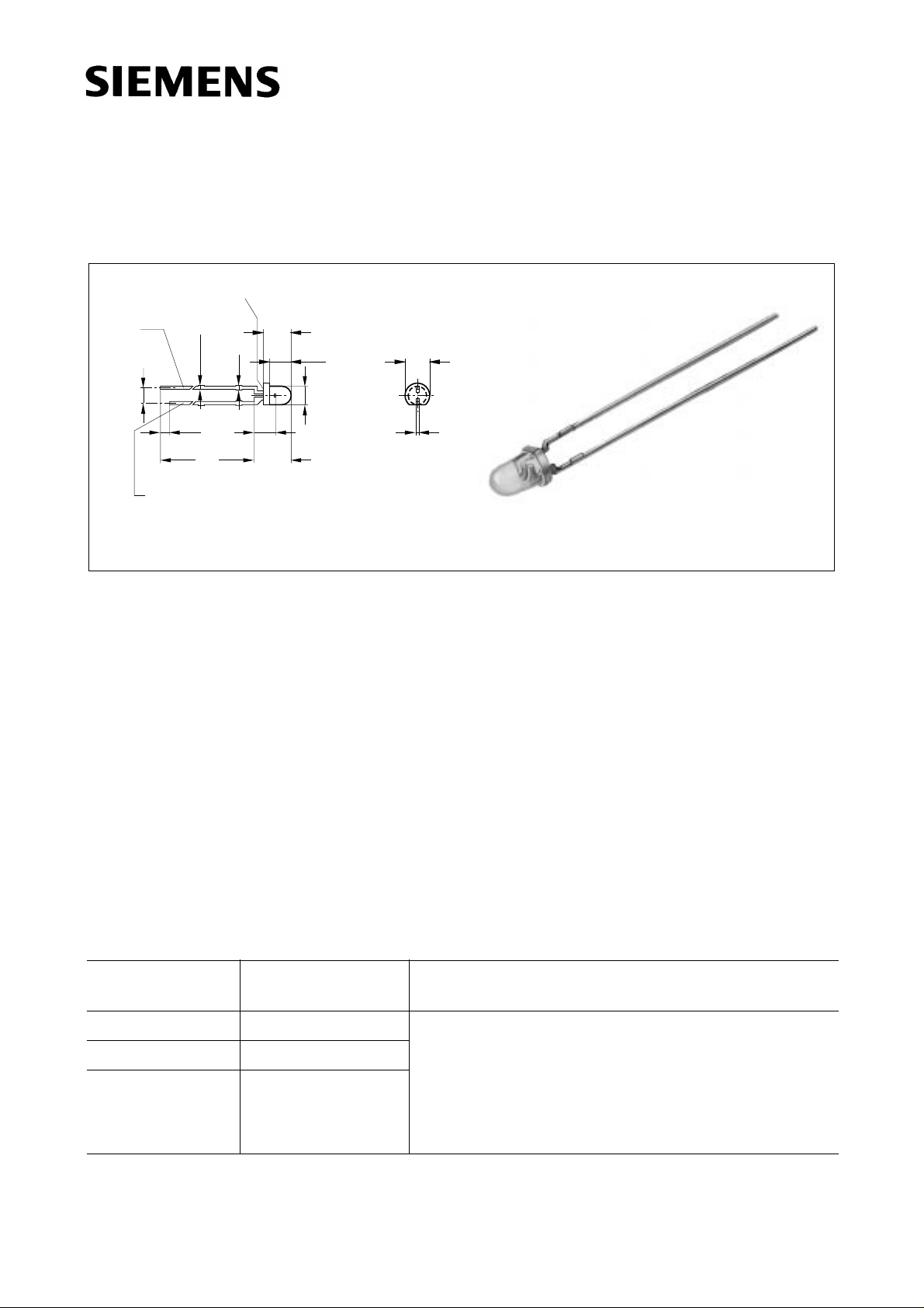
GaAs-IR-Lumineszenzdiode
GaAs Infrared Emitter
Area not flat
0.6
0.4
spacing
2.54 mm
Cathode
Anode (SFH 487)
Approx. weight 0.3 g
Maße in mm, wenn nicht anders angegeben/Dimensions in mm, unless otherwise specified.
0.7
0.4
0.8
1.8
1.2
29
27
(SFH 409)
0.4
5.2
4.5
(3.5)
Chip position
6.3
5.9
4.1
3.9
ø3.1
ø2.9
4.0
3.6
0.6
0.4
GEX06250
SFH 409
fex06250
Wesentliche Merkmale
● GaAs-IR-Lumineszenzdiode, hergestellt im
Schmelzepitaxieverfahren
● Hohe Zuverlässigkeit
● Hohe Impulsbelastbarkeit
● Gruppiert lieferbar
● Gehäusegleich mit SFH 309, SFH 487
Anwendungen
● Lichtschranken für Gleich- und
Wechsellichtbetrieb
● IR Fernsteuerungen
Typ
Type
Bestellnummer
Ordering Code
Gehäuse
Package
Features
● GaAs infrared emitting diode, fabricated in a
liquid phase epitaxy process
● High reliability
● High pulse handling capability
● Available in groups
● Same package as SFH 309, SFH 487
Applications
● Photointerrupters
● IR remote control of various equipment
SFH 409 Q62702-P860 3-mm-LED-Gehäuse (T 1), grau eingefärbt, AnSFH 409-1
1)
Q62702-P1001
schlüsse im 2.54-mm-Raster (
1
/10’’),
Kathodenkennzeichnung: kürzerer Anschluß
SFH 409-2 Q62702-P1002
3 mm LED package (T 1), grey-colored epoxy resin,
solder tabs lead spacing 2.54 mm (1/10’’),
cathode marking: short lead
1)
Nur auf Anfrage lieferbar.
1)
Available only on request.
Semiconductor Group 1 1997-11-01
Page 2
Grenzwerte (TA = 25 °C)
Maximum Ratings
SFH 409
Bezeichnung
Description
Betriebs- und Lagertemperatur
Operating and storage temperature range
Sperrschichttemperatur
Junction temperature
Sperrspannung
Reverse voltage
Durchlaßstrom
Forward current
Stoßstrom, τ≤10 µs,
D = 0
Surge current
Verlustleistung
Power dissipation
Wärmewiderstand
Thermal resistance
Symbol
Symbol
T
; T
op
stg
T
j
V
R
I
F
I
FSM
P
tot
R
thJA
Wert
Value
Einheit
Unit
– 55 ... + 100 °C
100 °C
5V
100 mA
3A
165 mW
450 K/W
Kennwerte (
T
= 25 °C)
A
Characteristics
Bezeichnung
Description
Wellenlänge der Strahlung
Wavelength at peak emission
I
= 100 mA, tp = 20 ms
F
max
I
max
Spektrale Bandbreite bei 50 % von
Spectral bandwidth at 50 % of I
I
= 100 m A, tp = 20 ms
F
Abstrahlwinkel
Half angle
Aktive Chipfläche
Active chip area
Abmessungen der aktive Chipfläche
Dimension of the active chip area
Abstand Chipoberfläche bis Linsenscheitel
Distance chip surface to lens top
Symbol
Symbol
λ
peak
Wert
Value
Einheit
Unit
950 nm
∆λ 55 nm
ϕ± 20 Grad
deg.
A
L × B
L
× W
H
0.09 mm
0.3 × 0.3 mm
2.6 mm
2
Kapazität,
V
R
= 0 V
C
o
25 pF
Capacitance
Semiconductor Group 2 1997-11-01
Page 3

Kennwerte (TA = 25 °C)
Characteristics
SFH 409
Bezeichnung
Description
Schaltzeiten, Ie von 10 % auf 90 % und von
90 % auf 10 %, bei IF = 100 mA, RL = 50 Ω
Switching times, Ie from 10 % to 90 % and
from 90 % to 10 %, IF = 100 mA, RL = 50 Ω
Durchlaßspannung
Forward voltage
I
= 100 mA, tp = 20 ms
F
I
= 1 A, tp = 100 µs
F
Sperrstrom
Reverse current
V
= 5 V
R
Gesamtstrahlungsfluß
Total radiant flux
I
= 100 mA, tp = 20 ms
F
Temperaturkoeffizient von I
I
= 100 mA
F
bzw. Φe,
e
Temperature coefficient of Ie or Φe,
I
= 100 mA
F
Temperaturkoeffizient von
V
, IF = 100 mA
F
Temperature coefficient of VF, IF = 100 mA
Symbol
Symbol
t
, t
r
f
V
F
V
F
I
R
Φ
e
TC
I
TC
V
Wert
Value
Einheit
Unit
1 µs
1.30 (≤ 1.5)
1.9 (≤ 2.5)
V
V
0.01 (≤ 1)µA
15 mW
– 0.55 %/K
– 1.5 mV/K
Temperaturkoeffizient von λ
Temperature coefficient of λ
, IF = 100 mA
peak
, IF = 100 mA
peak
TC
λ
Gruppierung der Strahlstärke Ie in Achsrichtung
gemessen bei einem Raumwinkel Ω = 0.01 sr
Grouping of radiant intensity Ie in axial direction
at a solid angle of Ω = 0.01 sr
Bezeichnung
Symbol Werte
Description
SFH 409 SFH 409-1
Strahlstärke
Radiant intensity
I
= 100 mA, tp = 20 ms
F
I
= 1 A, tp = 100 µs
F
1)
Nur auf Anfrage lieferbar.
1)
Available only on request.
I
e
I
e typ.
≥ 6.3
–
+ 0.3 nm/K
Values
1)
SFH 409-2
6.3 ... 12.575>10
120
Einheit
Unit
mW/sr
mW/sr
Semiconductor Group 3 1997-11-01
Page 4
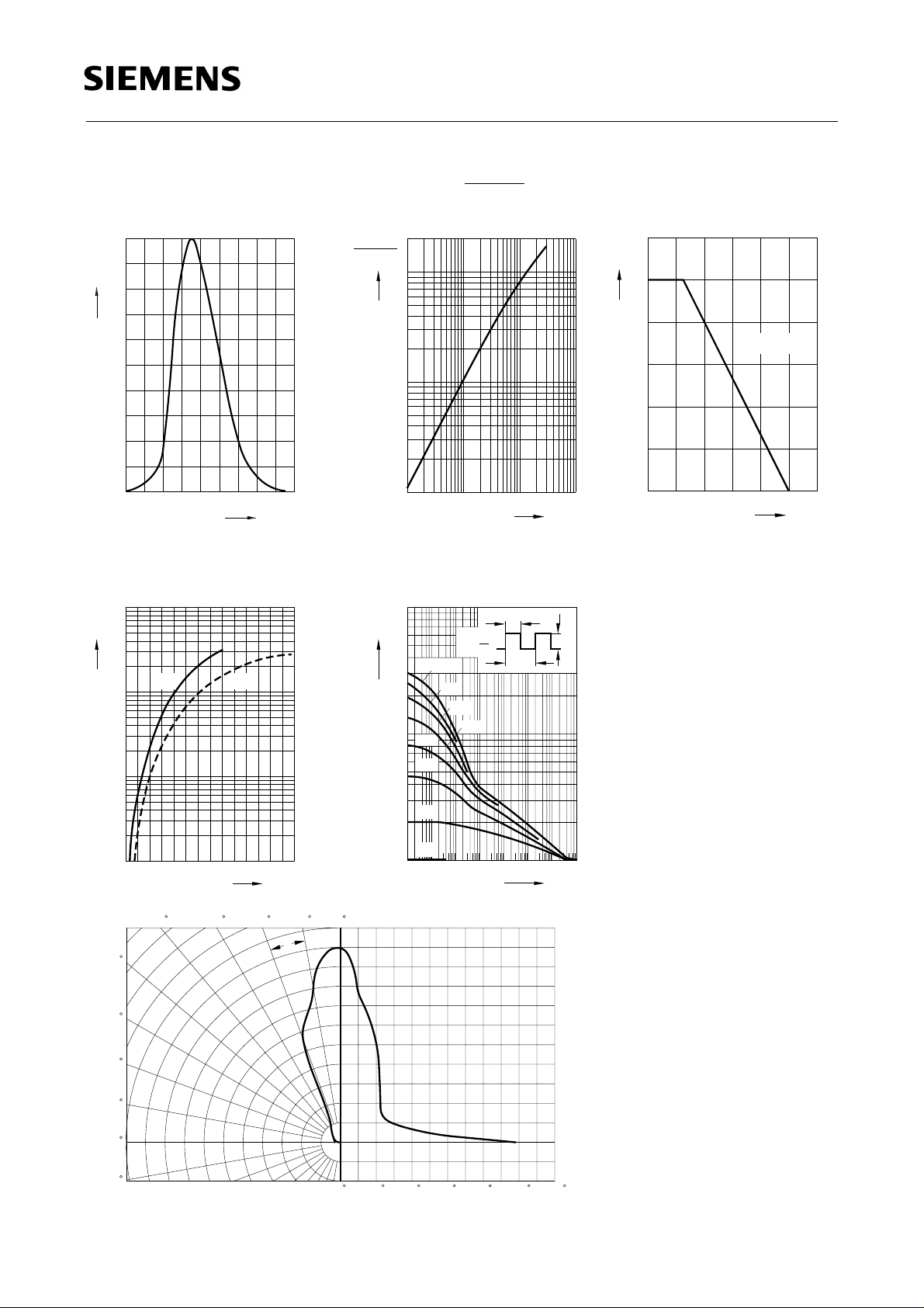
Relative spectral emission
I
= f (λ)
rel
100
%
Ι
rel
80
60
40
OHR01938
Radiant intensity
t
Single pulse,
Ι
e
mA)(100
Ι
e
10
10
= 20 µs
p
1
0
I
e
Ie100 mA
= f (IF)
OHR00864
SFH 409
Max. permissible forward current
I
= f (TA)
F
R
thjA
OHR00883
= 450 K/W
120
Ι
F
100
80
60
40
20
0
880 920 960 1000
Forward current
I
= f (VF), single pulse, tp = 20 µs
F
1
10
A
Ι
F
typ.
0
10
-1
10
-2
10
1
1.5 2 2.5 3 3.5 4 V 4.5
max.
Radiation characteristics I
50
nm
λ
rel
1060
OHR01041
V
F
= f (ϕ)
ϕ
20
-1
10
10
-2 -1
10
0
10 A 10
Ι
F
1
0
0
20 40 60 80 100 120mA˚C
T
A
Permissible pulse handling capability
I
= f (τ), TA = 25 °C,
F
duty cycle D = parameter
4
10
mA
Ι
F
5
D
=
0.005
τ
D
=
T
0.01
0.02
10
3
5
0.05
0.1
0.2
0.5
OHR00865
τ
Ι
F
T
DC
2
10
-5
-410-310-210-1100101102
10
10203040
0
1.0
0.8
τ
OHR01887
10s
60
70
80
90
100
0.6
0.4
0.2
0
02040 60 80 100 1200.40.60.81.0
Semiconductor Group 4 1997-11-01
 Loading...