

Page 1
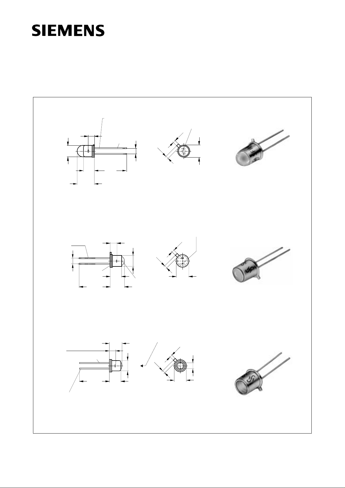
GaAs-IR-Lumineszenzdiode
GaAs Infrared Emitter
SFH 400
SFH 401
SFH 402
Chip position
ø4.8
ø4.6
5.3
5.0
7.4
6.6
Approx. weight 0.5 g
ø0.45
spacing
2.54 mm
welded
(2.7)
14.5
12.5
Cathode (SFH 480)
Anode
(SFH 216, SFH 231,
SFH 400)
ø0.45
14.5
12.5
(2.7)
Chip position
ø4.8
5.3
5.0
6.4
5.6
glass
lens
spacing
2.54mm
ø4.6
0.9
0.9
1.1
1.1
Radiant
Sensitive area
1.1
0.9
GEO06314
Anode
Cathode
1.1
= SFH 481
= SFH 401
0.9
ø5.6
ø5.3
GET06091
ø5.6
ø5.3
(package)
fet06090fet06091fet06092
Approx. weight 0.35 g
5.5
5.0
Chip position
Cathode (SFH 402, BPX 65)
Anode (SFH 482)
Approx. weight 0.5 g
Maße in mm, wenn nicht anders angegeben/Dimensions in mm, unless otherwise specified.
(2.7)
ø0.45
14.5
12.5
5.3
5.0
Radiant sensitive area
1.1
0.9
1.1
0.9
ø4.8
ø4.6
ø5.6
ø5.3
2.54
spacing
GET06013
Semiconductor Group 1 1998-04-16
Page 2
SFH 400,
SFH 401, SFH 402
Wesentliche Merkmale
● Hergestellt im Schmelzepitaxieverfahren
● Kathode galvanisch mit dem
Gehäuseboden verbunden
● Hohe Zuverlässigkeit
● SFH 400: Gehäusegleich mit SFH 216
● SFH 401: Gehäusegleich mit
BPX 43, BPY 62
● SFH 402: Gehäusegleich mit BPX 38,
BPX 65
Anwendungen
● Lichtschranken für Gleich- und
Wechsellichtbetrieb
● IR-Fernsteuerungen
● Industrieelektronik
● “Messen/Steuern/Regeln”
Features
● Fabricated in a liquid phase epitaxy process
● Cathode is electrically connected to the case
● High reliability
● SFH 400: Same package as SFH 216
● SFH 401: Same package as
BPX 43, BPY 62
● SFH 402: Same package as BPX 38,
BPX 65
Applications
● Photointerrupters
● IR remote control
● Industrial electronics
● For drive and control circuits
Typ
Type
Bestellnummer
Ordering Code
Gehäuse
Package
SFH 400 Q62702-P96 18 A3 DIN 41876 (TO-18), Glaslinse, hermetisch dichtes
SFH 400-3 Q62702-P784
SFH 401-2 Q62702-P786
SFH 401-3 Q62702-P787
Gehäuse, Anschlüsse im 2.54-mm-Raster (1/10’’)
18 A3 DIN 41876 (TO-18) glass lens, hermetically
sealed package, solder tabs lead spacing 2.54 mm
(1/10’’)
SFH 402 Q62702-P98
SFH 402-3 Q62702-P790
SFH 402-2 on request
Semiconductor Group 2 1998-04-16
Page 3
Grenzwerte (TC = 25 °C)
Maximum Ratings
SFH 400,
SFH 401, SFH 402
Bezeichnung
Description
SFH 401:
Betriebs- und Lagertemperatur
Operating and storage temperature range
SFH 400, SFH 402:
Betriebs- und Lagertemperatur
Operating and storage temperature range
Sperrschichttemperatur
Junction temperature
Sperrspannung
Reverse voltage
Durchlaßstrom
Forward current
Stoßstrom, tp = 10 µs, D = 0
Surge current
Verlustleistung
Power dissipation
Symbol
Symbol
T
; T
op
stg
T
; T
op
stg
T
j
V
R
I
F
I
FSM
P
tot
Wert
Value
Einheit
Unit
– 55 ... + 100 °C
– 55 ... + 125 °C
100 °C
5V
300 mA
3A
470 mW
Wärmewiderstand
Thermal resistance
Kennwerte (TA = 25 °C)
Characteristics
Bezeichnung
Description
Wellenlänge der Strahlung
Wavelength at peak emission
I
= 100 mA, tp = 20 ms
F
Spektrale Bandbreite bei 50 % von I
Spectral bandwidth at 50 % of I
I
= 100 mA, tp = 20 ms
F
max
Abstrahlwinkel
Half angle
SFH 400
SFH 401
SFH 402
Aktive Chipfläche
Active chip area
max
R
thJA
R
thJC
Symbol
Symbol
λ
peak
450
160
Wert
Value
K/W
K/W
Einheit
Unit
950 nm
∆λ 55 nm
ϕ
ϕ
ϕ
A
± 6
± 15
± 40
Grad
deg.
0.25 mm
2
Semiconductor Group 3 1998-04-16
Page 4

Kennwerte (TA = 25 °C)
Characteristics
SFH 400,
SFH 401, SFH 402
Bezeichnung
Description
Abmessungen der aktiven Chipfläche
Dimension of the active chip area
Abstand Chipoberfläche bis Linsenscheitel
Distance chip front to lens top
SFH 400
SFH 401
SFH 402
Schaltzeiten, Ie von 10 % auf 90 % und von
90 % auf 10 %, bei IF = 100 mA, RL = 50 Ω
Switching times, Ie from 10 % to 90 % and
from 90 % to 10 %, IF = 100 mA, RL = 50 Ω
Kapazität
Capacitance
V
= 0 V, f = 1 MHz
R
Durchlaßspannung
Forward voltage
I
= 100 mA, tp = 20 ms
F
I
= 1 A, tp = 100 µs
F
Sperrstrom
Reverse current
V
= 5 V
R
Gesamtstrahlungsfluß
Total radiant flux
I
= 100 mA, tp = 20 ms
F
Temperaturkoeffizient von Ie bzw. Φe,
I
= 100 mA
F
Temperature coefficient of Ie or Φe,
I
= 100 mA
F
Temperaturkoeffizient von VF, IF = 100 mA
Temperature coefficient of VF, IF = 100 mA
Symbol
Symbol
L × B
× W
L
H
H
H
t
, t
r
f
C
o
V
F
V
F
I
R
Φ
e
TC
I
TC
V
Wert
Value
Einheit
Unit
0.5 × 0.5 mm
4.0 ... 4.8
2.8 ... 3.7
2.1 ... 2.7
mm
mm
mm
1 µs
40 pF
1.30 (≤ 1.5)
1.90 (≤ 2.5)
V
V
0.01 (≤ 1)µA
8mW
– 0.55 %/K
– 1.5 mV/K
Temperaturkoeffizient von λ, IF = 100 mA
TC
λ
+ 0.3 nm/K
Temperature coefficient of λ, IF = 100 mA
Semiconductor Group 4 1998-04-16
Page 5

Gruppierung der Strahlstärke Ie in Achsrichtung
gemessen bei einem Raumwinkel Ω = 0.01 sr
Grouping of radiant intensity Ie in axial direction
at a solid angle of Ω = 0.01 sr
SFH 400,
SFH 401, SFH 402
Bezeichnung
Description
Strahlstärke
Radiant intensity
I
= 100 mA, tp = 20 ms
F
Strahlstärke
Radiant intensity
I
= 1 A, tp = 100 µs I
F
Symbol
Symbol
I
e min
I
e max
e typ.
SFH
400
20
–
SFH
400-3
32
–
SFH
401-2
10
20
Wert
Value
SFH
401-3
16
–
SFH
402
2.5
–
SFH
402-2
2.5
–
SFH
402-3
4
–
Einheit
Unit
mW/sr
mW/sr
300 320 120 190 40 40 40 mW/sr
Semiconductor Group 5 1998-04-16
Page 6

SFH 400,
SFH 401, SFH 402
Radiation characteristics, SFH 400 I
10203040
ϕ
50
60
70
80
90
100
Radiation characteristics, SFH 401 I
10203040
ϕ
50
rel
rel
= f (ϕ)
0
1.0
0.8
0.6
0.4
0.2
0
02040 60 80 100 1200.40.60.81.0
= f (ϕ)
0
1.0
0.8
OHR01883
OHR01884
60
70
80
90
100
Radiation characteristics, SFH 402 I
10203040
φ
50
60
70
80
rel
0.6
0.4
0.2
0
02040 60 80 100 1200.40.60.81.0
= f (ϕ)
0
1.0
0.8
0.6
0.4
0.2
OHR01885
90
100
0
02040 60 80 100 1200.40.60.81.0
Semiconductor Group 6 1998-04-16
Page 7

Relative spectral emission
I
= f (λ)
rel
100
%
Ι
rel
80
60
OHRD1938
Radiant intensity
t
2
1
= 20 µs
p
Single pulse,
10
Ι
e
Ι
(100 mA)
e
10
I
e
Ie100 mA
= f (IF)
OHR01037
SFH 400,
SFH 401, SFH 402
Max. permissible forward current
SFH 401, I
350
mA
Ι
F
300
250
200
= f (TA)
F
R
thJC
OHR00486
= 160 K/W
40
20
0
880 920 960 1000
Forward current, I
Single pulse,
1
10
A
Ι
F
0
10
-1
10
t
= 20 µs
p
typ.
= f (VF)
F
max.
nm
λ
OHR01040
1060
0
10
-1
10
-2 -1
10
10
0
10 A 10
Ι
F
Permissible pulse handling capability
I
= f (τ), TC = 25 °C,
F
R
= 160 K/W, duty cycleD = parameter
thJC
4
10
mA
Ι
F
5
0.2
3
10
t
P
=
D
T
0.5
5
DC
t
P
T
D =
0.005
0.01
0.02
0.05
0.1
OHR01937
Ι
F
150
= 450 K/W
R
thJA
100
50
1
0
0 20 40 60 80 100˚C
Max. permissible forward current
SFH 400, SFH 402, I
350
mA
Ι
F
300
250
200
150
R
thJA
100
50
F
R
thJC
= 450 K/W
= f (TA)
= 160 K/W
T
,
T
A
C
OHR00395
-2
10
1
1.5 2 2.5 33.54 4.5
V
V
F
10
2
10
-5
10-410-310
-2
0
s
10
τ
0
0 ˚C
20 40 60 80 100 130
T
,
T
A
C
Semiconductor Group 7 1998-04-16
 Loading...