

Page 1

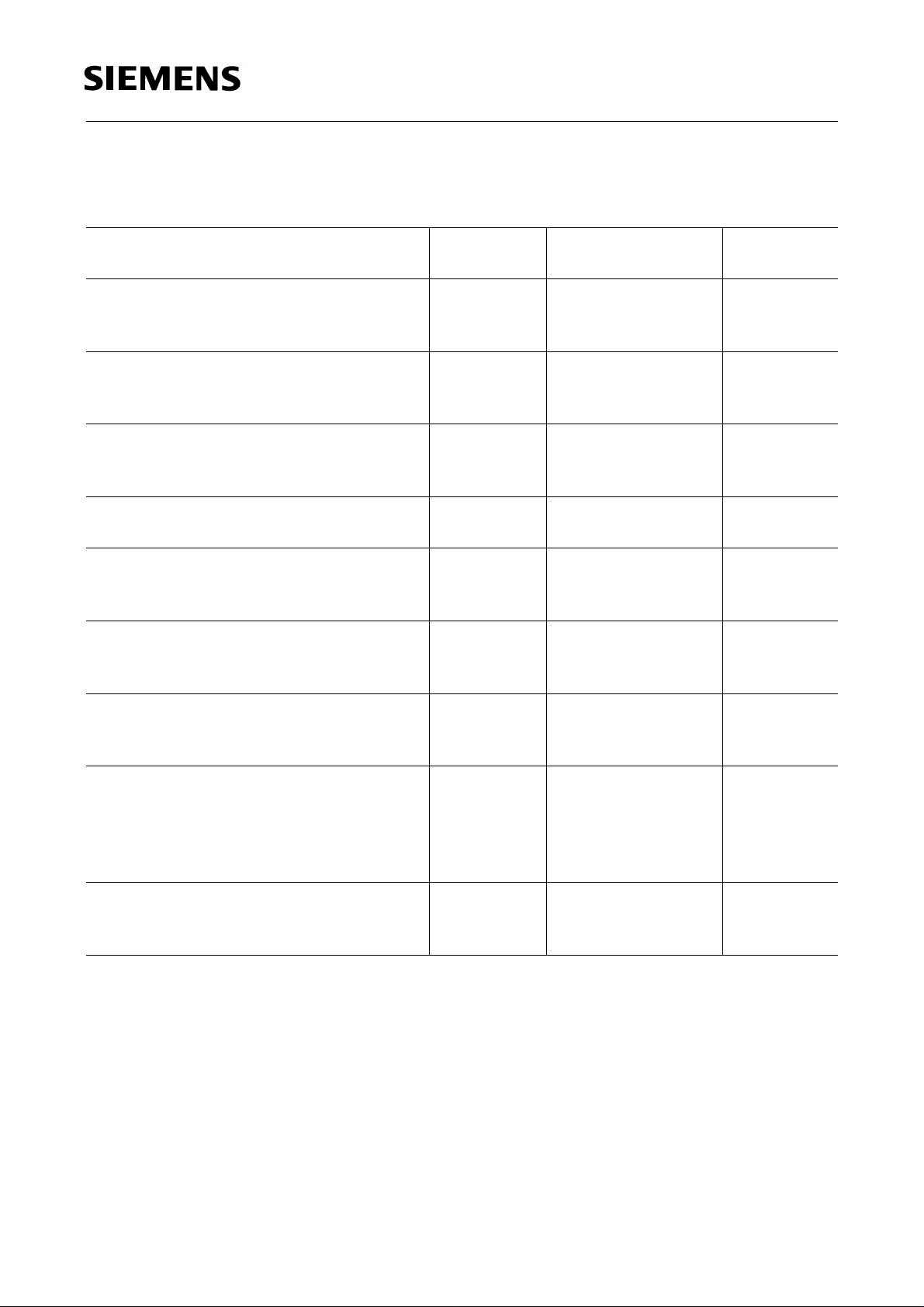
SMT Multi TOPLED
3.0
2.6
2.3
2.1
0.8
0.6
3.0
3.4
Package marking
Emission color : super-red
32
CA
EC
41
(2.4)
3.7
3.3
0.1
typ
1.1
0.5
2.1
1.7
0.18
0.12
SFH 331
0.9
0.7
0.6
0.4
GPL06924
Maβe in mm, wenn nicht anders angegeben/Dimensions in mm, unless otherwise specified.
Typ
Type
Bestellnummer
Ordering Code
SFH 331 Q62702-P1634
Wesentliche Merkmale
● Geeignet für Vapor-Phase Löten und
IR-Reflow Löten
Features
● Suitable for vapor-phase and IR-reflow
soldering
Semiconductor Group 1 1997-11-01
Page 2

Grenzwerte
Maximum Ratings
SFH 331
Bezeichnung
Description
Betriebstemperatur
Operating temperature range
Lagertemperatur
Storage temperature range
Sperrschichttemperatur
Junction temperature
Durchlaßstrom (LED)
Forward current (LED)
Kollektorstrom (Transistor)
Collector current (Transistor)
Stoßstrom
Surge current
t ≤ 10 µs, D = 0.005
Sperrspannung (LED)
Reverse voltage (LED)
Symbol
Symbol
T
op
T
stg
T
j
I
F
I
C
I
FM
V
R
Wert
Value
Einheit
Unit
LED Transistor
– 55 ... + 100 – 55 ... + 100
°
C
– 55 ... + 100 – 55 ... + 100 ˚C
+ 100 + 100 ˚C
30 – mA
–15mA
500 75 mA
5–V
Kollektor-Emitter Spannung (Transistor)
V
CE
–35V
Collector-emitter voltage (Transistor)
Verlustleistung
P
tot
100 165 mW
Total power dissipation
Wärmewiderstand Sperrschicht/Umgebung
Thermal resistance junction/ambient
Montage auf PC-Board*
(Padgröße ≥ 16 mm
2
)
R
th JA
450
450
K/W
mounting on pcb* (pad size ≥ 16 mm 2)
Sperrschicht / Lötstelle
R
th JS
350
–
K/W
junction / soldering joint
* PC-board: G30/FR4
Notes
Die angegebenen Grenzdaten gelten für den Chip, für den sie angegeben sind, unabhängig vom
Betriebszustand des anderen.
The stated max. ratings refer to the specified chip regardless of the operating status of the other
one.
Semiconductor Group 2 1997-11-01
Page 3
Kennwerte LED (TA = 25 ˚C)
Characteristics LED
SFH 331
Bezeichnung
Description
Wellenlänge des emittierten Lichtes (typ.)
Wavelength at peak emission (typ.)
I
= 10 mA
F
Dominantwellenlänge (typ.)
Dominant wavelength (typ.)
I
= 10 mA
F
Spektrale Bandbreite bei 50 %
Spectral bandwidth at 50 % I
I
= 10 mA
F
Abstrahlwinkel bei 50 %
Viewing angle at 50 % I
I
V
I
rel max
rel max
(Vollwinkel)
V
(typ.)
(typ.)
Durchlaßspannung (typ.)
Forward voltage (max.)
I
= 10 mA
F
Sperrstrom (typ.)
Reverse current (max.)
V
= 5 V
R
Kapazität (typ.)
Capacitance
V
= 0 V, f = 1 MHz
R
Schaltzeiten:
Switching times:
I
from 10 % to 90 % (typ.)
V
I
from 90 % to 10 % (typ.)
V
I
= 100 mA, tp = 10 µs, RL = 50 Ω
F
Lichtstärke (Gruppe JK) (typ.)
Luminous intensity (group JK)
I
= 10 mA
F
Symbol
Symbol
λ
peak
λ
dom
Wert
Value
Einheit
Unit
635 nm
628 nm
∆λ 45 nm
2ϕ 120 Grad
degr.
V
V
I
I
C
t
t
I
F
F
R
R
0
r
f
V
2.0
2.6
0.01
10
V
V
µA
µA
12 pF
300
150
ns
ns
6 (4.0 ... 12.5) mcd
Semiconductor Group 3 1997-11-01
Page 4

Kennwerte Fototransistor (TA = 25oC, λ = 950 nm)
Characteristics Phototransistor
SFH 331
Bezeichnung
Description
Wellenlänge der max. Fotoempfindlichkeit
Wavelength of max. sensitivity
Spektraler Bereich der Fotoempfindlichkeit
S = 10% von S
max
Spectral range of sensitivity
S = 10% of S
max
Bestrahlungsempfindliche Fläche (∅ 240 µm)
Radiant sensitive area (∅ 240 µm)
Abmessung der Chipfläche
Dimensions of chip area
Abstand Chipoberfläche zu Gehäuseoberfläche
Distance chip front to case surface
Halbwinkel
Half angle
Kapazität
Capacitance
V
= 0 V, f = 1 MHz, E = 0
CE
Dunkelstrom
Dark current
= 25 V, E = 0
V
CE
Fotostrom
Photocurrent
E
= 0.1 mW/cm2, VCE = 5 V
e
Anstiegszeit/Abfallzeit
Rise time/Fall time
I
= 1 mA, VCC = 5 V, RL = 1 kΩ
C
Kollektor-Emitter-Sättigungsspannung
Collector-emitter saturation voltage
= 5 µA, Ee = 0.1 mW/cm
I
C
2
Symbol
Symbol
λ
S max
Wert
Value
Einheit
Unit
860 nm
λ 380 ... 1150 nm
A 0.045 mm
2
L × B 0.45 × 0.45 mm × mm
H 0.5 ... 0.7 mm
ϕ±60 Grad
degr.
C
CE
I
CEO
I
PCE
tr, t
V
CEsat
f
5.0 pF
1 (≤ 200) nA
≥ 16 µA
7 µs
150 mV
Semiconductor Group 4 1997-11-01
Page 5

SFH 331
LED Radiation characteristics I
Phototransistor Directional characteristics S
50˚
60˚
70˚
80˚
90˚
100˚
1.0 0.8 0.6 0.4
LED Relative spectral emission I
V (λ) = Standard eye response curve
100
%
Φ
rel
80
= f (ϕ)
rel
0˚10˚20˚40˚ 30˚
ϕ
1.0
0.8
0.6
0.4
0.2
0
0˚ 20˚ 40˚ 60˚ 80˚ 100˚ 120˚
= f (λ), TA = 25 ˚C, IF= 20 mA
rel
V
λ
rel
= f (ϕ)
OHL01660
OHL02350
60
40
20
0
400 450 500 550 600 650 700
super-red
nm
λ
Semiconductor Group 5 1997-11-01
Page 6

SFH 331
Forward current IF = f (VF)
T
= 25 ˚C
A
2
10
Ι
mA
F
1
10
OHL02351
5
super-red
0
10
5
-1
10
1.0 1.4 1.8 2.2 2.6 3.0 3.4
V
V
F
Max. permissible forward current
I
= f (TA)
F
60
mA
Ι
F
50
OHL01661
Rel. luminous intensity
I
V
/ I
Ι
V
(10mA)
Ι
= f (IF), TA = 25 ˚C
V(10 mA)
1
10
V
0
10
5
-1
10
super-red
5
-2
10
5
-3
10
-1 0
55
10
10 10
Wavelength at peak emission
λ
= f (TA), IF = 20 mA
peak
690
λ
peak
nm
Perm. pulse handling capability I
Duty cycle D = parameter, T
OHL02316
12
mA
10
Ι
F
10
Ι
F
mA
10
10
Dominant wavelength λ
I
= 20 mA
OHL02104
F
690
λ
dom
5
nm
= f (tp)
F
= 25 ˚C
A
3
t
P
D
=
T
D
=
0.005
0.01
0.02
0.05
0.1
2
0.2
OHL01686
t
P
Ι
F
T
0.5
DC
1
= f (TA)
dom
s10-510-410-310-210-110010
t
p
OHL02105
1
40
30
20
10
0
Forward current V
I
= 10 mA
F
2.4
V
F
V
2.2
2.0
1.8
1.6
= f (TA)
F
super-red
orange
yellow
800
˚C
T
A
OHL02106
green
pure-green
650
650
super-red
630
610
590
570
100604020
550
orange
yellow
green
pure-green
0 20406080100
˚C
T
A
630
610
590
570
550
super-red
orange
yellow
green
pure-green
0 20406080100
˚C
T
A
Rel. luminous intensity
I
/ I
V
Ι
V
Ι
V
(25 ˚C)
= f (TA), IF = 10 mA
V(25 ˚C)
2.0
1.6
1.2
0.8
0.4
orange
super-red
yellow
green
pure-green
OHL02150
1.4
0 20406080100
˚C
T
A
0.0
0 20406080100
˚C
T
A
Semiconductor Group 6 1997-11-01
Page 7

SFH 331
Phototransistor
Rel. spectral sensitivity S
100
S
rel
%
80
60
40
20
0
400 600 800 1000 1200
Total power dissipation
P
= f (TA)
tot
200
mW
P
tot
160
120
80
40
0
20 40 60 80 ˚C 100
0
rel
= f (λ)
OHF01121
nm
λ
OHF00871
T
A
Photocurrent I
E
= Parameter
e
0
10
mA
Ι
PCE
-1
10
-2
10
0
5 10 15 20 25 30 35
PCE
= f (VCE),
Capacitance
C
= f (VCE), f = 1 MHz, E = 0
CE
5.0
C
pF
CE
4.0
3.5
3.0
2.5
2.0
1.5
1.0
0.5
0
-2
10
10-110010110
0.5
0.25
0.1
1
mW
cm
mW
cm
mW
cm
mW
cm
OHF01529
2
2
2
2
V
V
CE
OHF01528
V
V
CE
Dark current
I
= f (VCE), E = 0
CEO
1
10
nA
Ι
CEO
0
10
-1
10
-2
10
-3
10
0 5 10 15 20 25 30 35V
Photocurrent I
V
= 5 V
CE
1.6
Ι
PCE
Ι
25
PCE
1.4
PCE/IPCE25
1.2
1.0
0.8
0.6
0.4
0.2
2
0
0 25 50 75 100
-25
OHF01527
V
o
= f (TA),
OHF01524
T
CE
C
A
Dark current
I
= f (TA), VCE= 5 V, E = 0
CEO
3
10
Ι
CEO
2
10
1
10
0
10
-1
10
-25nA0 25 50 75 100
OHF01530
˚C
T
A
Photocurrent I
3
10
µ
A
Ι
PCE
2
10
1
10
0
10
-1
10
-3
10
= f (Ee), VCE= 5 V
PCE
-2
10
mW/cm
OHF01924
4
3
2
2
E
0
10
e
Semiconductor Group 7 1997-11-01
 Loading...