

Page 1

LCD TV
SERVICE MANUAL
CAUTION
BEFORE SERVICING THE CHASSIS,
READ THE SAFETY PRECAUTIONS IN THIS MANUAL.
CHASSIS : ML-041A
MODEL RZ-26LZ50
website:http://biz.LGservice.com
e-mail:http://www.LGEservice.com/techsup.html
Page 2

CONTENTS
CONTENTS .............................................................................................. 2
PRODUCT SAFETY ..................................................................................3
SPECIFICATION........................................................................................4
TIMING CHART .......................................................................................10
ADJUSTMENT INSTRUCTION................................................................11
TROUBLE SHOOTING............................................................................16
BLOCK DIAGRAM...................................................................................21
WIRING DIAGRAM..................................................................................23
EXPLODED VIEW .................................................................................. 24
EXPLODED VIEW PARTS LIST..............................................................25
REPLACEMENT PARTS LIST ............................................................... 26
SVC. SHEET ...............................................................................................
Page 3
SAFETY PRECAUTIONS
Many electrical and mechanical parts in this chassis have special safety-related characteristics. These parts are identified by in the
Schematic Diagram and Replacement Parts List.
It is essential that these special safety parts should be replaced with the same components as recommended in this manual to prevent
X-RADIATION, Shock, Fire, or other Hazards.
Do not modify the original design without permission of manufacturer.
General Guidance
An isolation Transformer should always be used during the
servicing of a receiver whose chassis is not isolated from the AC
power line. Use a transformer of adequate power rating as this
protects the technician from accidents resulting in personal injury
from electrical shocks.
It will also protect the receiver and it's components from being
damaged by accidental shorts of the circuitry that may be
inadvertently introduced during the service operation.
If any fuse (or Fusible Resistor) in this TV receiver is blown,
replace it with the specified.
When replacing a high wattage resistor (Oxide Metal Film Resistor,
over 1W), keep the resistor 10mm away from PCB.
Keep wires away from high voltage or high temperature parts.
X-RAY Radiation
Warning:
To determine the presence of high voltage, use an accurate high
impedance HV meter.
Adjust brightness, color, contrast controls to minimum.
Measure the high voltage.
The meter reading should indicate
23.5
1.5KV: 14-19 inch, 26
1.5KV: 19-21 inch,
29.0
1.5KV: 25-29 inch, 30.0 1.5KV: 32 inch
If the meter indication is out of tolerance, immediate service and
correction is required to prevent the possibility of premature
component failure.
Before returning the receiver to the customer,
always perform an AC leakage current check on the exposed
metallic parts of the cabinet, such as antennas, terminals, etc., to
be sure the set is safe to operate without damage of electrical
shock.
Leakage Current Cold Check(Antenna Cold Check)
With the instrument AC plug removed from AC source, connect an
electrical jumper across the two AC plug prongs. Place the AC
switch in the on position, connect one lead of ohm-meter to the AC
plug prongs tied together and touch other ohm-meter lead in turn to
each exposed metallic parts such as antenna terminals, phone
jacks, etc.
If the exposed metallic part has a return path to the chassis, the
measured resistance should be between 1MΩ and 5.2MΩ.
When the exposed metal has no return path to the chassis the
reading must be infinite.
An other abnormality exists that must be corrected before the
receiver is returned to the customer.
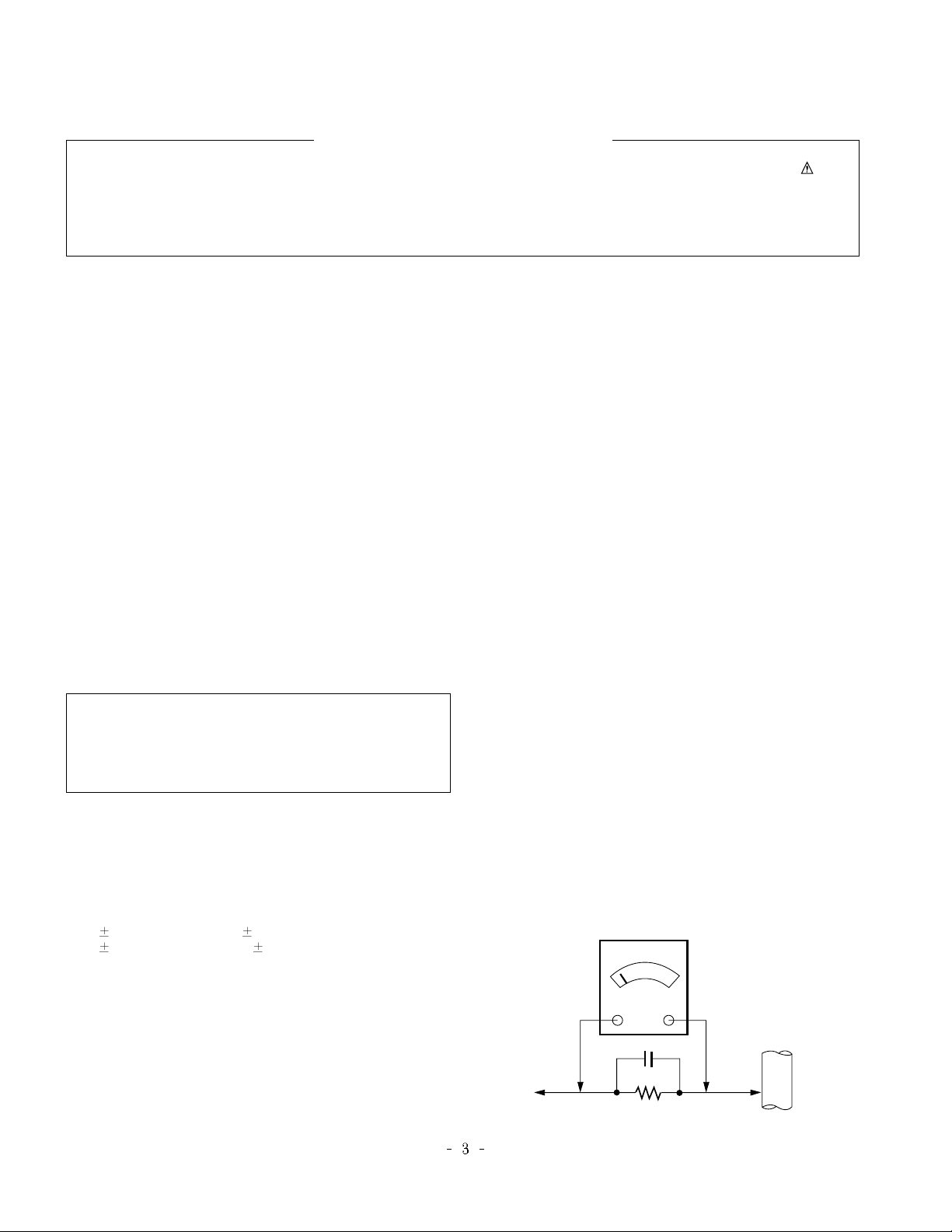
Leakage Current Hot Check (See below Figure)
Plug the AC cord directly into the AC outlet.
Do not use a line Isolation Transformer during this check.
Connect 1.5K/10watt resistor in parallel with a 0.15uF capacitor
between a known good earth ground (Water Pipe, Conduit, etc.)
and the exposed metallic parts.
Measure the AC voltage across the resistor using AC voltmeter
with 1000 ohms/volt or more sensitivity.
Reverse plug the AC cord into the AC outlet and repeat AC voltage
measurements for each exposed metallic part. Any voltage
measured must not exceed 0.75 volt RMS which is corresponds to
0.5mA.
In case any measurement is out of the limits specified, there is
possibility of shock hazard and the set must be checked and
repaired before it is returned to the customer.
Leakage Current Hot Check circuit
The source of X-RAY RADIATION in this TV receiver is the High
Voltage Section and the LCD PANEL.
For continued X-RAY RADIATION protection, the replacement
panel must be the same type panel as specified in the
Replacement Parts List.
IMPORTANT SAFETY NOTICE
0.15uF
To Instrument's
exposed
METALLIC PARTS
AC Volt-meter
1.5 Kohm/10W
Good Earth Ground
such as WATER PIPE,
CONDUIT etc.
Page 4

CAUTION: Before servicing receivers covered by this service
manual and its supplements and addenda, read and follow the
SAFETY PRECAUTIONS on page 3 of this publication.
NOTE: If unforeseen circumstances create conflict between the
following servicing precautions and any of the safety precautions on
page 3 of this publication, always follow the safety precautions.
Remember: Safety First.
General Servicing Precautions
1. Always unplug the receiver AC power cord from the AC power
source before;
a. Removing or reinstalling any component, circuit board
module or any other receiver assembly.
b. Disconnecting or reconnecting any receiver electrical plug or
other electrical connection.
c. Connecting a test substitute in parallel with an electrolytic
capacitor in the receiver.
CAUTION: A wrong part substitution or incorrect polarity
installation of electrolytic capacitors may result in an
explosion hazard.
2. Test high voltage only by measuring it with an appropriate high
voltage meter or other voltage measuring device (DVM,
FETVOM, etc) equipped with a suitable high voltage probe.
Do not test high voltage by "drawing an arc".
3. Do not spray chemicals on or near this receiver or any of its
assemblies.
4. Unless specified otherwise in this service manual, clean
electrical contacts only by applying the following mixture to the
contacts with a pipe cleaner, cotton-tipped stick or comparable
non-abrasive applicator; 10% (by volume) Acetone and 90% (by
volume) isopropyl alcohol (90%-99% strength)
CAUTION: This is a flammable mixture.
Unless specified otherwise in this service manual, lubrication of
contacts in not required.
5. Do not defeat any plug/socket B+ voltage interlocks with which
receivers covered by this service manual might be equipped.
6. Do not apply AC power to this instrument and/or any of its
electrical assemblies unless all solid-state device heat sinks are
correctly installed.
7. Always connect the test receiver ground lead to the receiver
chassis ground before connecting the test receiver positive
lead.
Always remove the test receiver ground lead last.
8. Use with this receiver only the test fixtures specified in this
service manual.
CAUTION: Do not connect the test fixture ground strap to any
heat sink in this receiver.
Electrostatically Sensitive (ES) Devices
Some semiconductor (solid-state) devices can be damaged easily
by static electricity. Such components commonly are called
Electrostatically Sensitive (ES) Devices. Examples of typical ES
devices are integrated circuits and some field-effect transistors and
semiconductor "chip" components. The following techniques
should be used to help reduce the incidence of component
damage caused by static by static electricity.
1. Immediately before handling any semiconductor component or
semiconductor-equipped assembly, drain off any electrostatic
charge on your body by touching a known earth ground.
Alternatively, obtain and wear a commercially available
discharging wrist strap device, which should be removed to
prevent potential shock reasons prior to applying power to the
unit under test.
2. After removing an electrical assembly equipped with ES
devices, place the assembly on a conductive surface such as
aluminum foil, to prevent electrostatic charge buildup or
exposure of the assembly.
3. Use only a grounded-tip soldering iron to solder or unsolder ES
devices.
4. Use only an anti-static type solder removal device. Some solder
removal devices not classified as "anti-static" can generate
electrical charges sufficient to damage ES devices.
5. Do not use freon-propelled chemicals. These can generate
electrical charges sufficient to damage ES devices.
6. Do not remove a replacement ES device from its protective
package until immediately before you are ready to install it.
(Most replacement ES devices are packaged with leads
electrically shorted together by conductive foam, aluminum foil
or comparable conductive material).
7. Immediately before removing the protective material from the
leads of a replacement ES device, touch the protective material
to the chassis or circuit assembly into which the device will be
installed.
CAUTION: Be sure no power is applied to the chassis or circuit,
and observe all other safety precautions.
8. Minimize bodily motions when handling unpackaged
replacement ES devices. (Otherwise harmless motion such as
the brushing together of your clothes fabric or the lifting of your
foot from a carpeted floor can generate static electricity
sufficient to damage an ES device.)
General Soldering Guidelines
1. Use a grounded-tip, low-wattage soldering iron and appropriate
tip size and shape that will maintain tip temperature within the
range or 500
F to 600 F.
2. Use an appropriate gauge of RMA resin-core solder composed
of 60 parts tin/40 parts lead.
3. Keep the soldering iron tip clean and well tinned.
4. Thoroughly clean the surfaces to be soldered. Use a mall wirebristle (0.5 inch, or 1.25cm) brush with a metal handle.
Do not use freon-propelled spray-on cleaners.
5. Use the following unsoldering technique
a. Allow the soldering iron tip to reach normal temperature.
(500
F to 600 F)
b. Heat the component lead until the solder melts.
c. Quickly draw the melted solder with an anti-static, suction-
type solder removal device or with solder braid.
CAUTION: Work quickly to avoid overheating the
circuitboard printed foil.
6. Use the following soldering technique.
a. Allow the soldering iron tip to reach a normal temperature
(500
F to 600 F)
b. First, hold the soldering iron tip and solder the strand against
the component lead until the solder melts.
c. Quickly move the soldering iron tip to the junction of the
component lead and the printed circuit foil, and hold it there
only until the solder flows onto and around both the
component lead and the foil.
CAUTION: Work quickly to avoid overheating the circuit
board printed foil.
d. Closely inspect the solder area and remove any excess or
splashed solder with a small wire-bristle brush.
SERVICING PRECAUTIONS
Page 5

IC Remove/Replacement
Some chassis circuit boards have slotted holes (oblong) through
which the IC leads are inserted and then bent flat against the
circuit foil. When holes are the slotted type, the following technique
should be used to remove and replace the IC. When working with
boards using the familiar round hole, use the standard technique
as outlined in paragraphs 5 and 6 above.
Removal
1. Desolder and straighten each IC lead in one operation by gently
prying up on the lead with the soldering iron tip as the solder
melts.
2. Draw away the melted solder with an anti-static suction-type
solder removal device (or with solder braid) before removing the
IC.
Replacement
1. Carefully insert the replacement IC in the circuit board.
2. Carefully bend each IC lead against the circuit foil pad and
solder it.
3. Clean the soldered areas with a small wire-bristle brush.
(It is not necessary to reapply acrylic coating to the areas).
"Small-Signal" Discrete Transistor
Removal/Replacement
1. Remove the defective transistor by clipping its leads as close as
possible to the component body.
2. Bend into a "U" shape the end of each of three leads remaining
on the circuit board.
3. Bend into a "U" shape the replacement transistor leads.
4. Connect the replacement transistor leads to the corresponding
leads extending from the circuit board and crimp the "U" with
long nose pliers to insure metal to metal contact then solder
each connection.
Power Output, Transistor Device
Removal/Replacement
1. Heat and remove all solder from around the transistor leads.
2. Remove the heat sink mounting screw (if so equipped).
3. Carefully remove the transistor from the heat sink of the circuit
board.
4. Insert new transistor in the circuit board.
5. Solder each transistor lead, and clip off excess lead.
6. Replace heat sink.
Diode Removal/Replacement
1. Remove defective diode by clipping its leads as close as
possible to diode body.
2. Bend the two remaining leads perpendicular y to the circuit
board.
3. Observing diode polarity, wrap each lead of the new diode
around the corresponding lead on the circuit board.
4. Securely crimp each connection and solder it.
5. Inspect (on the circuit board copper side) the solder joints of
the two "original" leads. If they are not shiny, reheat them and if
necessary, apply additional solder.
Fuse and Conventional Resistor
Removal/Replacement
1. Clip each fuse or resistor lead at top of the circuit board hollow
stake.
2. Securely crimp the leads of replacement component around
notch at stake top.
3. Solder the connections.
CAUTION: Maintain original spacing between the replaced
component and adjacent components and the circuit board to
prevent excessive component temperatures.
Circuit Board Foil Repair
Excessive heat applied to the copper foil of any printed circuit
board will weaken the adhesive that bonds the foil to the circuit
board causing the foil to separate from or "lift-off" the board. The
following guidelines and procedures should be followed whenever
this condition is encountered.
At IC Connections
To repair a defective copper pattern at IC connections use the
following procedure to install a jumper wire on the copper pattern
side of the circuit board. (Use this technique only on IC
connections).
1. Carefully remove the damaged copper pattern with a sharp
knife. (Remove only as much copper as absolutely necessary).
2. carefully scratch away the solder resist and acrylic coating (if
used) from the end of the remaining copper pattern.
3. Bend a small "U" in one end of a small gauge jumper wire and
carefully crimp it around the IC pin. Solder the IC connection.
4. Route the jumper wire along the path of the out-away copper
pattern and let it overlap the previously scraped end of the good
copper pattern. Solder the overlapped area and clip off any
excess jumper wire.
At Other Connections
Use the following technique to repair the defective copper pattern
at connections other than IC Pins. This technique involves the
installation of a jumper wire on the component side of the circuit
board.
1. Remove the defective copper pattern with a sharp knife.
Remove at least 1/4 inch of copper, to ensure that a hazardous
condition will not exist if the jumper wire opens.
2. Trace along the copper pattern from both sides of the pattern
break and locate the nearest component that is directly
connected to the affected copper pattern.
3. Connect insulated 20-gauge jumper wire from the lead of the
nearest component on one side of the pattern break to the lead
of the nearest component on the other side.
Carefully crimp and solder the connections.
CAUTION: Be sure the insulated jumper wire is dressed so the
it does not touch components or sharp edges.
Page 6
1. Application range
This specification is applied to ML-041A chassis.
2. Requirement for Test
Testing for standard of each part must be followed in below
condition.
(1) Temperature: 25°C ± 5°C
(2) Humidity: 65% ± 10%
(3) Power: Standard input voltage (AC 100-240V, 50/60Hz)
(4) Measurement must be performed after heat-run more than
15min.
(5) Adjusting standard for this chassis is followed a special
standard.
SPECIFICATION
NOTE : Specifications and others are subject to change without notice for improvement
.
4.General Specification(TV)
1
2
3
4
5
6
7
8
9
Video input applicable system
Receivable broadcasting system
RF input channel
Input voltage
Picture size
Tuning system
Operting environment
Storage environment
Display
1)PAL-D/K,B/G,I
2)NTSC-M
3)SECAM NTSC 4.43’
1)PAL/SECAM BG
2)PAL/SECAM DK
3)PAL I/I
4)SECAM L/L’
5)NTSC M
6)PAL-N/M
7)NTSC M
VHF : E2 ~ E12
UHF : E21 ~ E69
CATV : S1 ~ S20
HYPER : S21 ~ S41
L/L’ : B,C,D
VHF : 2 ~ 13
UHF : 14 ~ 69
CATV : 1 ~ 125
VHF Low : 1~M10
VHF High : 4~S22
UHF : S23~62
AC 100 - 240V/ 50Hz,60HZ
660.40 mm
FVS 100 program
FS
1)Temp : 0 ~ 40 deg
2)Humidity : 85%
3)Temp : -20 ~ 60 deg
4)Humidity : 85%
LCD Module
Item Specification Remark
No.
EU/Non-EU(RZ/RT)
(PAL Market)
7)NTSC Area(RM)
PAL
FRANCE
NTSC
JAPAN
26”
PAL, 200PR.(Option)
NTSC
LPL, AUO
Page 7
5.General Specification(Monitor)
1
2
3
4
5
6
Panel
Frequency range
Control function
Component Jack
D4 Jack
(525i,525p,750p,1125i)
Power ON
Stand by
DPMS Mode
Power off
LCD Module
26” TFT WXGA LCD
H:31 ~ 61KHz, V: 56 ~ 75Hz
1) Contrast/ Brightness
2) H- Position/ V-Position
3) Tracking : Clock/Phase
4) Auto Configure
5) Reset
1: Y
3: Pb
5: Pr
7: Line1 Ready
9: LINE2
11: LINE3
13: Line3 Ready
2: Y GND
4: Pb GND
6: Pr GND
8: LINE1
10: Line2 Ready
12: SWITCH GND
14: SWITCH
1280 horiz By 768 vert. pixels
RGB strip arrangement
Hard coating(3H), Anti-glare
treatment of the front polarizer
Item Specification RemarkUnit
No.
DVI-I input
Middle east
/NTSC Only
Japan only
LED
Red
Red dimmed
Red dimmed
*.
(H) x (V) x (D)
H/V-Sync
ON/ON
OFF/ON
ON/OFF
-
Video
Active
OFF
OFF
-
LPL
AUO
LPL
AUO
Power consumption
≤ Max 170
≤ 3.0
≤typ.25
-
W
W
W
W
mm
mm
Type
Size
Pixel Pitch
Pixel Format
Coating
Back Light
622 x 389 x 53
620.8 x 389 x 37
0.1475 x 0.4425 x RGB
0.1475 x 0.4425 x RGB
LPL
AUO
CCFL
CCFL
Page 8
7.Feature and Function
1
2
3
4
5
6
7
8
9
10
11
12
13
14
15
16
17
18
19
20
21
22
23
24
Teletext
REMOCON
AV input
S-AV input
Component input
PERI TV connector
PERI TV connector
RGB input
RS-232
Discrete IR
D-sub audio input
2 Carrier stereo
NICAM stereo
2 Carrier dual
NICAM dual
DW(Double Window) mode
MW(Multi Window) mode
Film mode
Noise reduction
Progressive scan
Motion detection
SRS WOW
Swivel Speaker
EZ-pip
TOP, FLOF, LIST 10 page
NEC code
1
1
2
Half SCART: 1
Full SCART: 1
1
1
1
1
BG,DK
BG,I,LL’
BG,DK
BG,I,LL’
X
X
O
X
O
O
X
X
X
Item Specification Remark
No.
Top(option)
PAL/NTSC
Rear(RT/RM)
Side
Side, Rear(RT/RM) 480i, 576i
Rear(RZ)
Rear(RZ)
DVI
D-Sub 9 pin(RM)
(RM)
Stereo
6.Optical Feature(LCD Module)
Item RemarkSpecification
Viewing Angle
<CR
10>
Luminance
Contrast Ratio
CIE Color Coordinates
Typical
MAX/MIN
ALL white/All back
LPL
R/L, U/D
Luminance(cd/
)
Variation
LPL
176,176
450
1.3
500
0.284
0.295
WHITE
RED
Green
Blue
W
X
W
Y
W
r
Y
r
X
g
Y
g
Xb
Yb
Typ.
Typ.
Typ.
Typ.
Typ.
Typ.
Typ.
Typ.
AUO
TBD
600
600
0.285
0.293
TBD
TBD
TBD
TBD
TBD
TBD
No.
1
2
3
4
Page 9
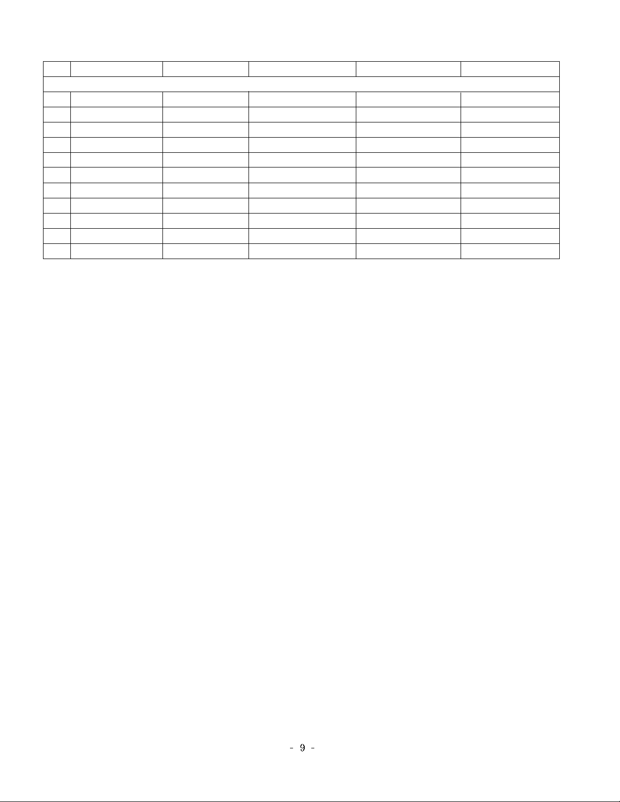
NO
1
2
3
4
5
6
7
8
9
10
11
Resoluton
640 x 480
640 x 480
640 x 480
800 x 600
800 x 600
800 x 600
800 x 600
1024 x 768
1024 x 768
1024 x 768
1280 x 768
H-freq(kHz)
31.469
35
37.500
35.156
37.879
48.077
46.875
48.363
56.476
60.023
47.693
V-freq(Hz)
59.94
67
75.00
56.25
60.31
72.18
75.00
60.00
70.06
75.02
60.00
Proposed
VESA(VGA)
VESA(VGA)
VESA(VGA)
VESA(SVGA)
VESA(SVGA)
VESA(SVGA)
VESA(SVGA)
VESA(XGA)
VESA(XGA)
VESA(XGA)
VESA(WXGA)
Pixel clock(MHz)
25.17
30.24
31.50
36.00
40.00
50.00
49.50
65.00
75.00
78.75
80.125
8.PC Input Mode
DVI-PC, Analog RGB
Page 10
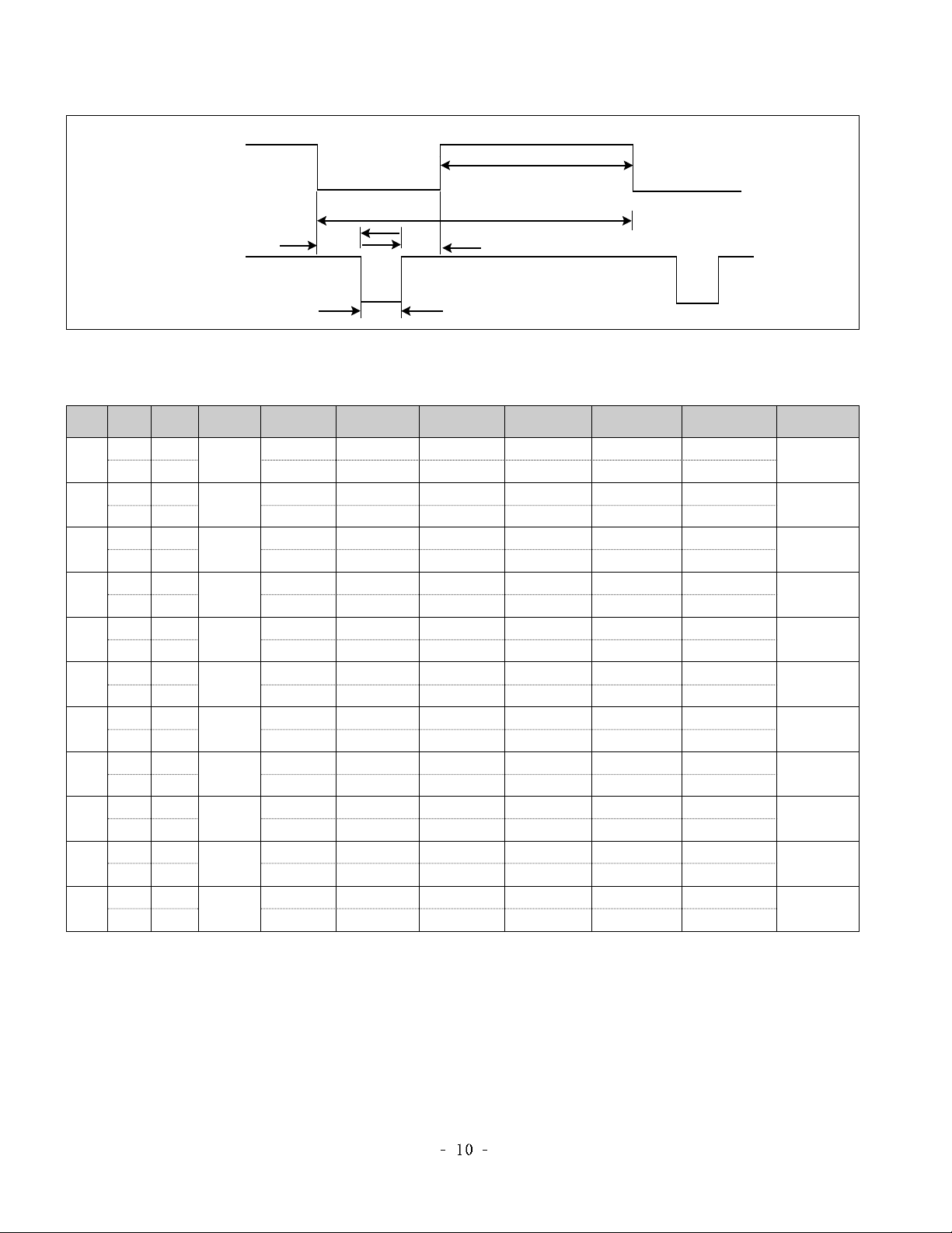
TIMING CHART
<< Dot Clock (MHz), Horizontal Frequency (kHz), Vertical Frequency (Hz), Horizontal etc... (µs), Vertical etc... (ms) >>
H + 31.469 800 640 16 96 48
V – 59.94 525 480 10 2 33
H – 37.5 840 640 16 64 120
V – 75 500 480 1 3 16
H – 35.156 1024 800 24 72 128
V – 56.25 625 600 1 2 22
H – 35 864 640 64 64 96
V + 66.667 525 480 3 3 39
H + 37.879 1056 800 40 128 88
V + 60.317 628 600 1 4 23
H + 48.077 1040 800 56 120 64
V + 72.188 666 600 37 6 23
H+/– 46.875 1056 800 16 80 160
V+/– 75.0 625 600 1 3 21
H – 48.363 1344 1024 24 136 160
V – 60.004 806 768 3 6 29
H + 56.476 1328 1024 24 136 144
V + 70.069 806 768 3 6 29
H + 60.023 1312 1024 16 96 176
V – 75.029 800 768 1 3 28
H + 47.776 1664 1280 64 128 192
V – 59.870 798 768 3 7 20
Mode
H/V
Sort
1
2
3
4
5
6
7
8
9
10
11
25.175
30.240
31.5
36
40.0
50.0
49.5
65.0
75
78.75
79.50
640x480
640x480
800x600
640x480
800x600
800x600
800x600
1024x768
1024x768
1024x768
1280x768
Sync
Polarity
Frequency
Dot
Clock
Total Period
(E)
Video Active Time
(A)
Sync Duration
(D)
Back Porch
(F)
Front Porch
(B)
Resolution
VIDEO
A
E
D
SYNC
C
B
Page 11
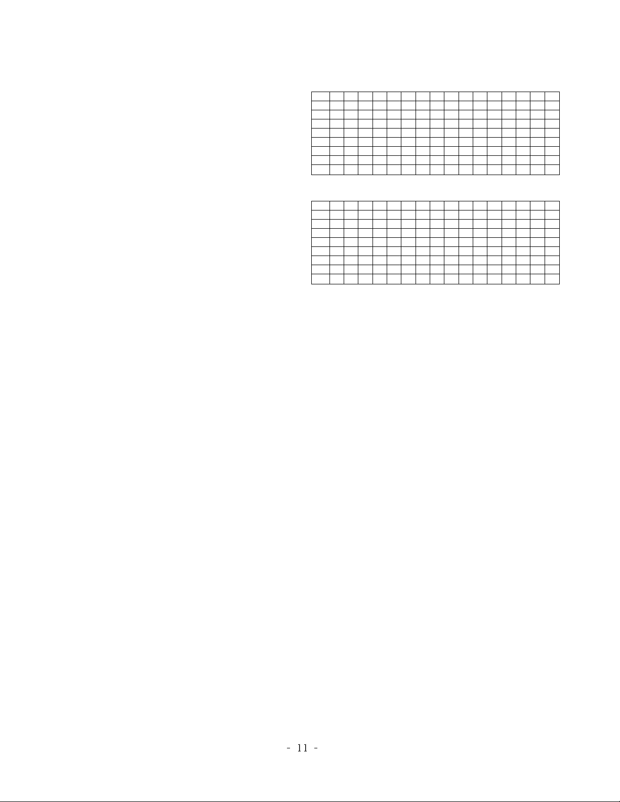
1. Application Object
This instruction is for the application to the LCD TV.
2. Adjustment
2.1 Auto Gain/Offset adjustment
2.1.1 Adjustment preparation
1) Conduct Heat Run with the White Pattern for more than 30
minutes.
2) Connect the signals of Pattern Generator to DVI-I Jack of
LCD TV.
2.1.2 Auto Gain/Offset adjustment
1) Use the Pattern Generator (801GF, VG819) to authorize
XGA (1024 X 768) for resolution and 16 gray scale signals
for patterns. Or authorize 16 gray scale (11 gray scale)
signals in accordance with VG819.
2) Press the IN-START Key to convert to the adjustment
mode using the adjustment (SVC) remote controller, and
press VOL+ Key at the AutoGain menu.
3) Once the adjustment is completed, press the Enter Key to
save and finish the adjustment
2.2
EDID (The Extended Display Identification Data) setting
1) Connect D-Sub to DVI-I Cable with DVI-I Jack.
2) Select TV as an input source and press the [Instart] key on
the remote control.
3) Select the OPT3 from the OSD menu and set Analog or
Digital for DDC data selection.
4) Select Analog for analog data, and Digital for digital data.
5) Connect the DDC automation equipment and write the
DDC data.
2.2.1 EDID DATA
[DDC DATA Analog]
[DDC DATA Digital]
ADJUSTMENT INSTRUCTION
00 01 02 03 04 05 06 07 08 09 0A 0B 0C 0D 0E 0F
00 00 FF FF FF FF FF FF 00 1E 6D 00 56 01 01 01 01
10 0C 0E 01 03 98 46 2B 96 EE E8 AA A1 57 49 9C 25
20 10 48 4B BF EE 00 31 40 3B CA 45 40 61 40 81 C0
30 81 CF 01 01 01 01 40 1F 00 90 51 00 1B 30 40 88
40 37 00 BC AE 21 00 00 1C 00 00 00 FD 00 38 4B 1F
50 3D 0A 00 0A 20 20 20 20 20 20 00 00 00 FC 00 52
60 5A 32 36 4C 5A 35 30 0A 20 20 20 20 00 00 00 FC
70 00 0A 20 20 20 20 20 20 20 20 20 20 20 20 00 55
00 01 02 03 04 05 06 07 08 09 0A 0B 0C 0D 0E 0F
00 00 FF FF FF FF FF FF 00 1E 6D FF 55 01 01 01 01
10 0C 0E 01 03 18 46 2B 78 EE E8 AA A1 57 49 9C 25
20 10 48 4B AB 8C 00 45 4F 61 4F 81 CF 01 01 01 01
30 01 01 01 01 01 01 40 1F 00 90 51 00 1B 30 40 88
40 37 00 BC AE 21 00 00 1C 00 00 00 FD 00 38 4B 1F
50 3D 0A 00 0A 20 20 20 20 20 20 00 00 00 FC 00 52
60 5A 32 36 4C 5A 35 30 0A 20 20 20 20 00 00 00 FC
70 00 0A 20 20 20 20 20 20 20 20 20 20 20 20 00 FE
Page 12
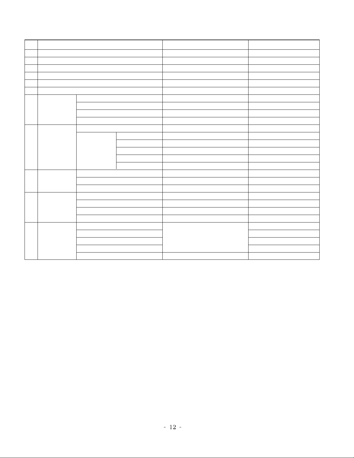
NO ITEM CONDITION REMARK
Power
Volume Level
Main Pcture Input
Main Last Channel
Mute
ARC
Station
Picture
Sound
Special
PC
1
2
3
5
8
9
10
11
14
15
16
Auto Program
Manual Program
Program Edit
Favorite Program
PSM
SSM
AVL
Balance
Input
Child Lock
Auto sleep
Language
H-Position
V-Position
Clock
Phase
Auto Configure
Dynamic Contrast
Brightness
Colour
Sharpness
Tint
Off
30
TV
Pr 01
Off
16:9
None
Dynamic
80
40
70
70
0
Flat
Off
0
TV
Off
Off
English(Area Management)
Variable by each mode
NTSC OPTION
3. Shipping Conditions
Page 13
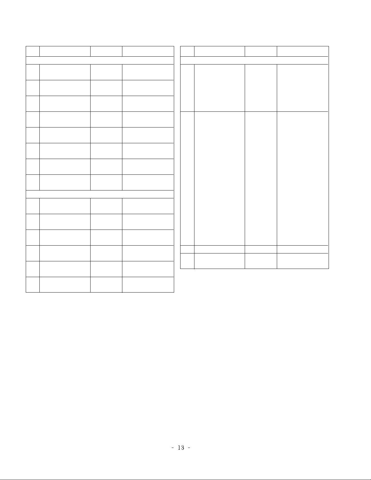
NO ITEM
CONDITION
REMARK
1
2
3
4
5
6
7
8
1
2
3
4
5
6
Side AV
SCART
PC
SideComp
16:9
200PR
Text
ACMS
HiDev
Hotel
Top
I II SAVE
Turbo Vol
Ch/Aus
1
1
1
1
1
0
1
1
0
0
1
1
0
0
0: Side AV Off
1: Side AV On
0: SCART Off
1: SCART On
0: PC Off
1: PC On
0: SideComp Off
1: SideComp On
0: Wide Off
1: Wide On
0: 100 Program
1: 200 Program
0: Text Off
1: Text On
0: ACMS On
1: ACMS Off
0: HiDev Off
1: HiDev On
0: Hotel Off
1: Hotel On
0: Top Off
1: Top On
0:
Ch. Sound Non Memory
1:
Ch. Sound Memory
0:
except below area(Off)
1:
Middle-east Area Vol On
0:
except below area(Off)
1:
China, Australia On
Option 1
Option 2
NO ITEM
CONDITION
REMARK
1
2
3
4
Language
Txt Lang
Inch opt
DDCi
1
0
0
Analog
0: Eng Only
1: EU5
2:
12 nations(Europe)
3: Eng + Chines
4: Eng + Arab + Urdu
5: Eng + FARSI
0: WEST EU
1: EAST EU 1
2:
TURKY EU
3: EAST EU 2
4: CYRILLIC 1
5: CYRILLIC 2
6: CYRILLIC 3
7:
TURKY GRE
1
8:
TURKY GRE
2
9:
TURKY GRE
3
10:
ARAB FRAN
11:
ARAB ENG
12:
ARAB HEB
1
13:
ARAB HEB
2
14:
FARSI ENG
15:
FARSI FRA
16:
FARI ALL
reserved
Analog: Analog
Digital: Digital
Option 3
*Option(PAL)
Page 14
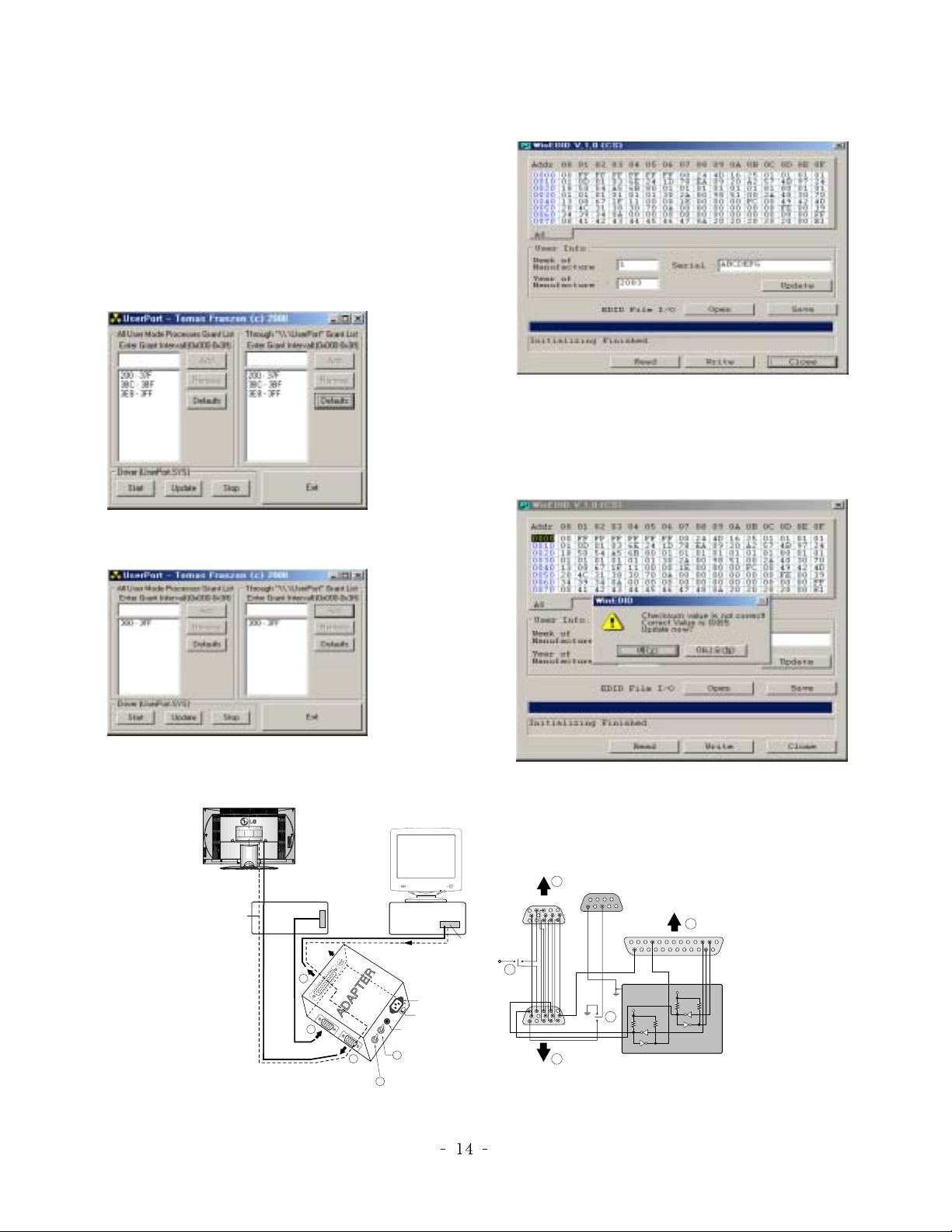
EDID ADJUSTMENT
Windows EDID V1.0 User Manual
Operating System: MS Windows 98, 2000, XP
Port Setup: Windows 98 => Don’t need setup
Windows 2000, XP => Need to Port Setup.
This program is available to LCD Monitor only.
1. Port Setup
a) Copy “UserPort.sys” file to
“c:\WINNT\system32\drivers” folder
b) Run Userport.exe
c) Remove all default number
d) Add 300-3FF
e) Click Start button.
f) Click Exit button.
2. EDID Read & Write
1) Run WinEDID.exe
2) Edit Week of Manufacture, Year of Manufacture,
Serial Number
a) Input User Info Data
b) Click “Update” button
c) Click “ Write” button
Figure 1. Cable Connection
Video Signal
Generator
Control Line
A
69
1
IBM
Compatible PC
Not used
RS232C
C
PARALLEL
VGS
MONITOR
A
B
POWER
ST
V-SYNC
E
F
V-Sync On/Off Switch
(Switch must be ON.)
220
Power LED
ST Switch
PARALLEL PORT
Power inlet (required)
Power Select Switch
(110V/220V)
5V
OFF ON
F
15
10
5
5
11
6
1
13
25
ON
OFF
B
5V
E
74LS06
C
1
14
5V
4.7K
4.7K
74LS06
4.7K
Page 15
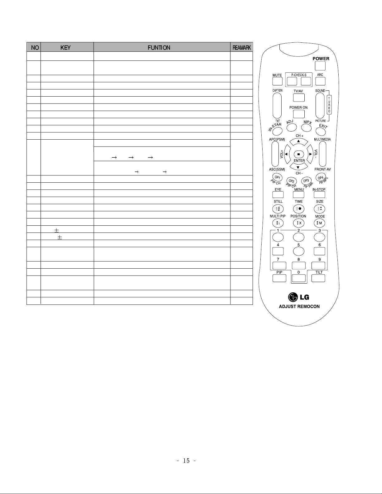
SVC REMOCON
1 POWER
2 POWER ON
3 MUTE
4 P-CHECK
5 S-CHECK
6 ARC
7 CAPTION
8 TXT
9 TV/AV
10 TURBO SOUND
11 TURBO PICTURE
12 IN-START
13 ADJ
14 MPX
15 EXIT
16 APC(PSM)
17 ASC(SSM)
18 MULTIMIDIA
19 FRONT-AV
20 CH
21 VOL
22 ENTER
23 EYE
24 MENU
25 IN-STOP
26 TIME
27 MODE
28 0~9
To turn the TV on or off
To turn the TV on automatically if the power is supplied to the TV. (Use the
POWER key to deactivate): It should be deactivated when delivered.
To activate the mute function.
To check TV screen image easily.
To check TV screen sound easily
To select size of the main screen (Normal, Spectacle, Wide or Zoom)
Switch to closed caption broadcasting
To toggle on/off the teletext mode
To select an external input for the TV screen
To start turbo sound
To start turbo picture
To enter adjustment mode when manufacturing the TV sets.
To adjust the screen voltage (automatic):
In-start
mute Adjust AV(Enter into W/B adjustment mode)
W/B adjustment (automatic):
After adjusting the screen W/B adjustment Exit two times (Adjustment completed)
To enter into the adjustment mode. To adjust horizontal line and sub-brightness.
To select the multiple sound mode (Mono, Stereo or Foreign language)
To release the adjustment mode
To easily adjust the screen according to surrounding brightness
To easily adjust sound according to the program type
To check component input
To check the front AV
To move channel up/down or to select a function displayed on the screen.
To adjust the volume or accurately control a specific function.
To set a specific function or complete setting.
To set a function that will automatically adjust screen status to match
the surrounding brightness so natural color can be displayed.
To select the functions such as video, voice, function or channel.
To set the delivery condition status after manufacturing the TV set.
Displays the telext time in the normal mode.
Enables to select the sub code in the telext mode
Used as Mode in the teletext mode
To manually select the channel.
Shortcut keys
Shortcut keys
Shortcut keys
Use the AV
key to enter
the screen
W/B
adjustment
mode.
Shortcut keys
Shortcut keys
Page 16
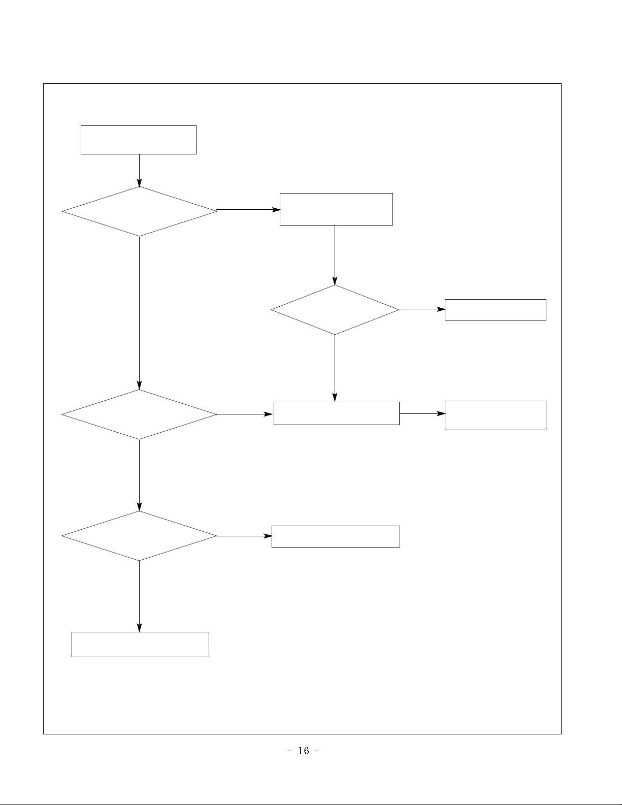
TROUBLESHOOTING
No power
(LED indicator off)
Check short of main B/D
or Change Power B/D
Change IC1300,IC4 or IC8
Change LED Assy
Change L808,L809
(F801,F802)
Check 24V or 12V
of Power B/D
Check Output of
IC1300, IC4 or IC8
Check LED Assy
Check P101 Connector
Faill
Faill Faill
Change L3, L1300
Check Output of
L3, L1300
Faill
Pass
Faill
Pass
Pass
Pass
:[A]Process
Page 17
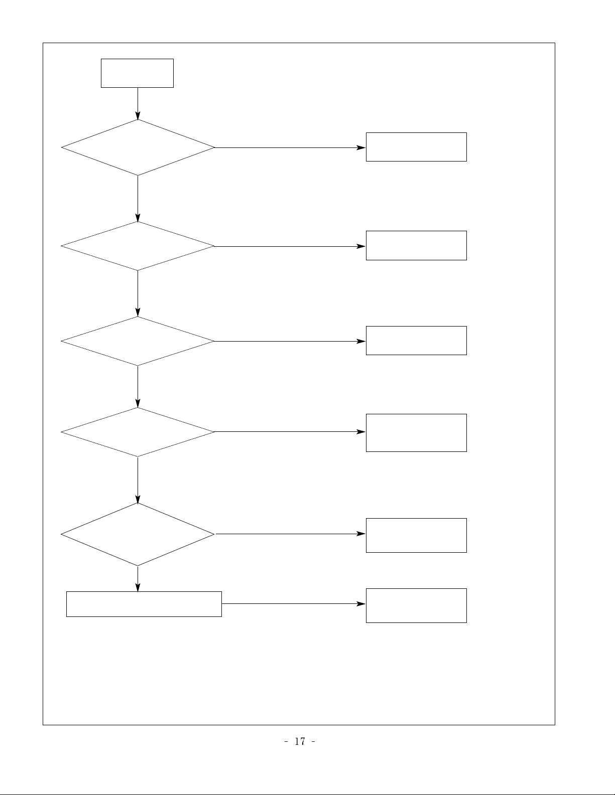
No Raster
Check LED Status
on display unit
Check the input/
Output of IC901
Check L900,L901
L902,L903
Check inverter
Connector or inverter
Check input source cable and jack
Repeat A PROCESS
Faill
Change L900,L901,
L902,L903
Faill
Change IC901
Faill
Change inverter
connector or inverter
Faill
Change panel link
cable or module
Faill
Change module\
Faill
Check panel link
Cable or module
Pass
Pass
Pass
Pass
:[B]Process
Page 18
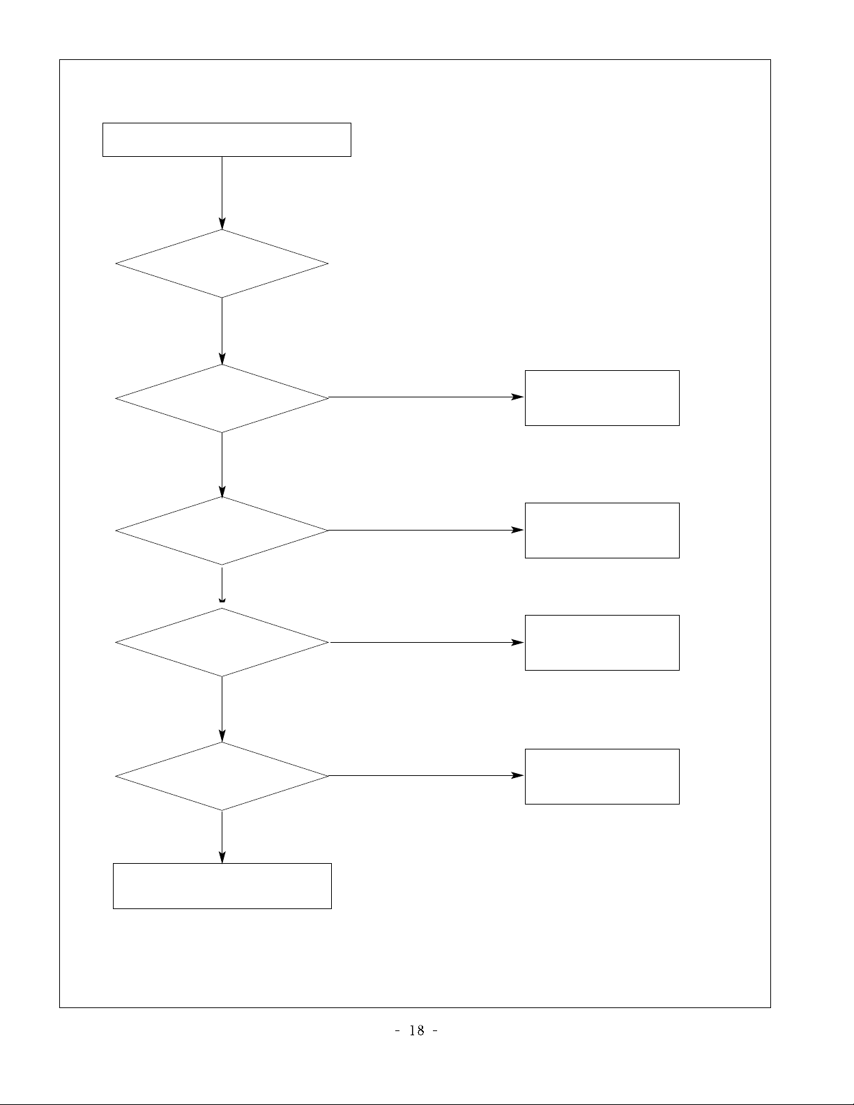
No Raster on Component signal
Change
Q310,Q315,Q316
Check the signal of
Q310,Q315,Q316
Repeat
[A] Process
Check the input/
output of IC1
Check the input/
output of IC901
Check input source cable and jack
Faill
Re-soldering or
Change the defect part
Faill
Re-soldering or
Change the defect part
Faill
Pass
Pass
Pass
Check the input/output
of IC500, IC600
Re-soldering or
Change the defect part
Faill
Pass
Page 19
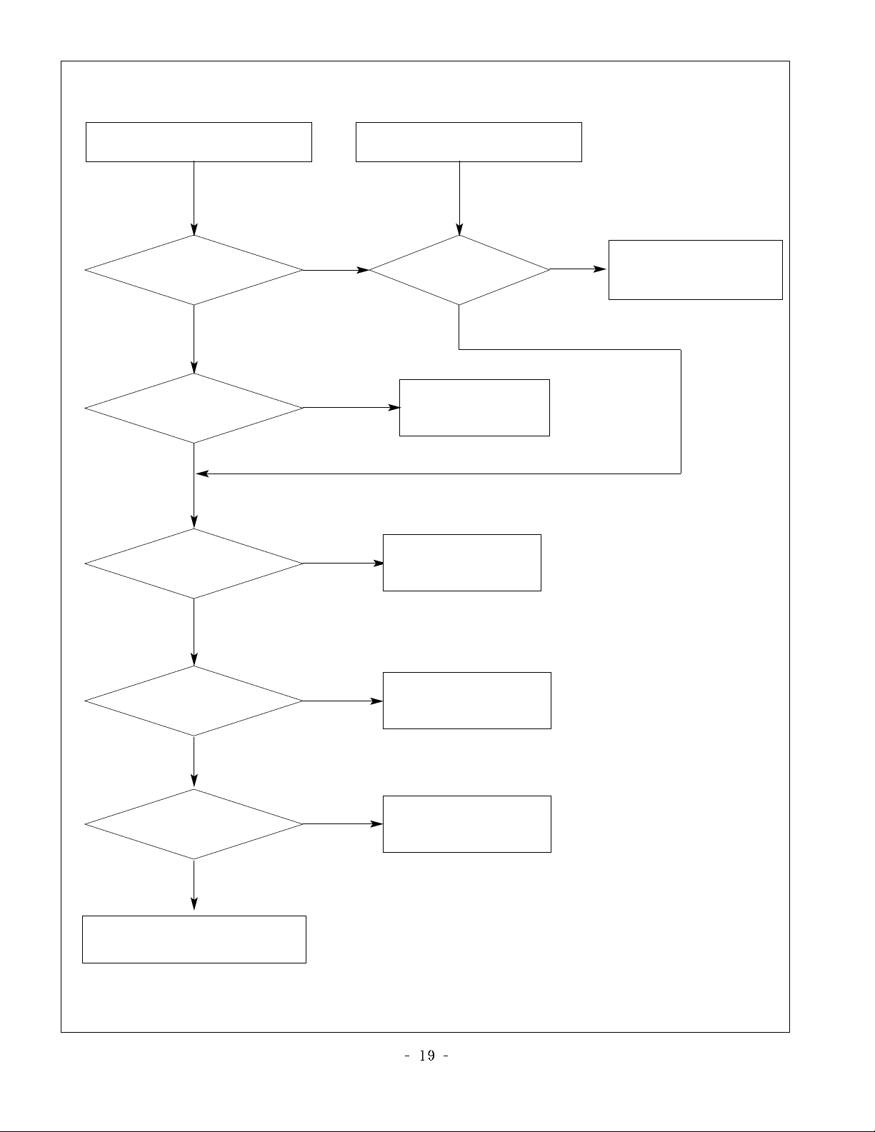
No Raster on AV Signa
(Video1,Video2, S-Video)
No Raster on TV(RF) signal
Change C316,C317,
Q308,Q313
Check the signal of
C316,C317,Q308,Q313
Repeat
[A] Process
Check the output of
TU1000
Check the input/output
of IC1
Check the input/output
of IC500, IC600
Check input source cable and jack
Faill
Faill
Faill
Faill
Re-soldering or
Change the defect part
Faill
Re-soldering or
Change the defect part
Check 5V, 33V of TU1000
Re-soldering or
Change the defect part
Pass
Pass
Pass
Check the input/output
of IC901
Faill
Re-soldering or
Change the defect part
Pass
Pass
Page 20
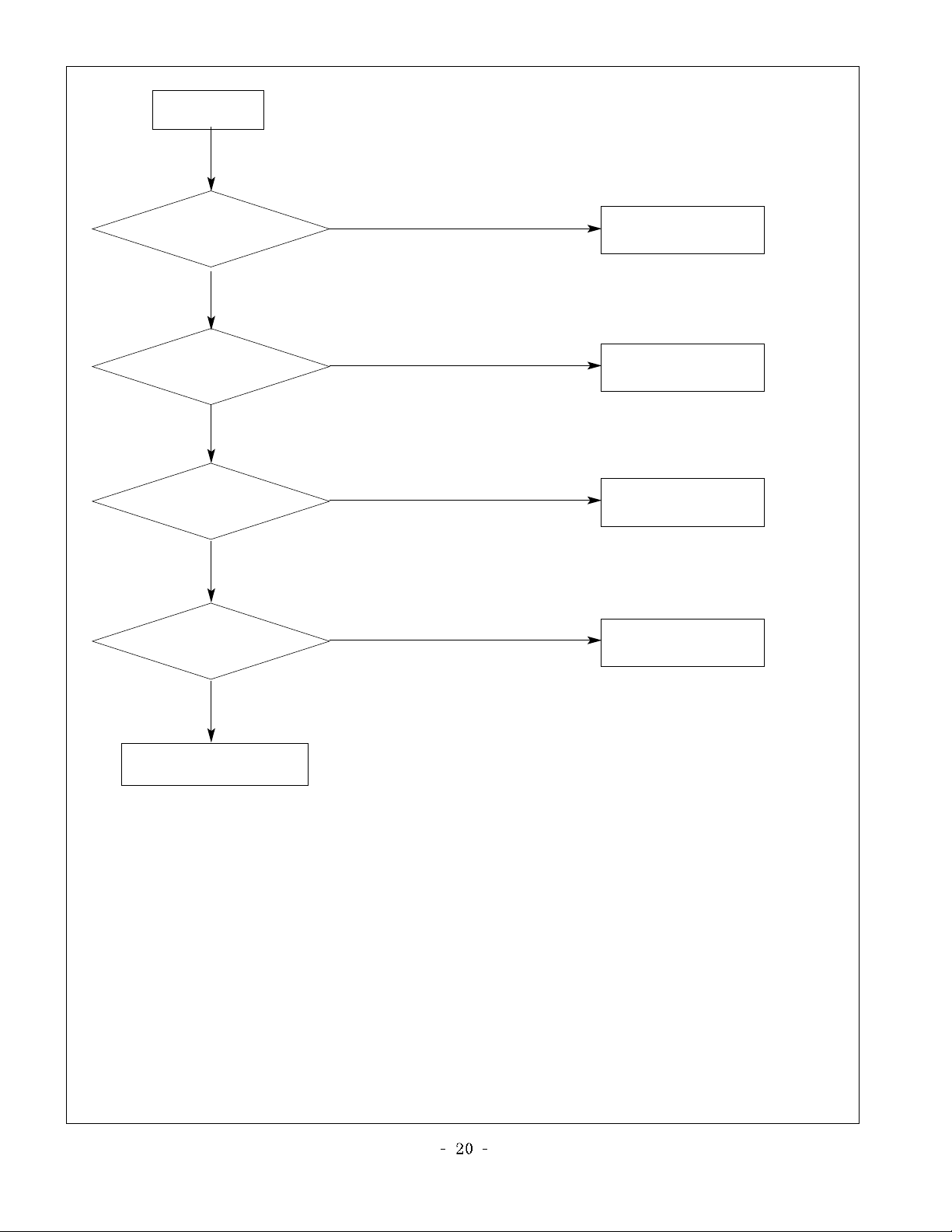
No Sound
Check the speaker wire
Change source input
Check the
input source
Faill
Pass
Re-soldering or
Change the defect part
Check the input/output
of IC1
Faill
Pass
Re-soldering or
Change the defect part
Check the input/output
of IC100,IC101
Faill
Pass
Change speaker
Check the speaker
Faill
Pass
Page 21
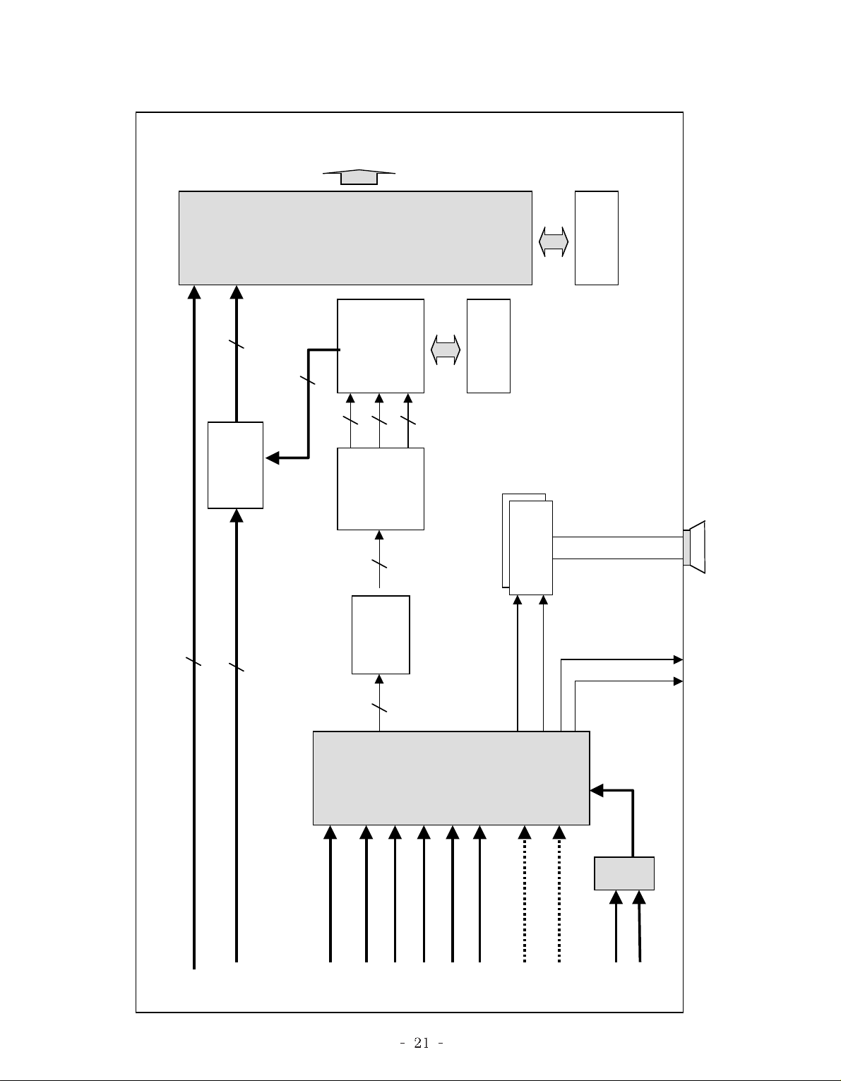
BLOCK DIAGRAM
LVDS
or TTL
OUT
GM5221
SCALER
(IC901)
ROM
(IC900)
8
DVI
3
R,G,B
S/W
(IC850)
M52758
3
PC_R,G,B
3
R,G,B
FLI2300
8
R
G
MST9883
R,G,B
SM5301
R,G,B
(IC500)
8
B
ADC
(IC600)
3
(IC800)
3
RAM
(IC501)
8
(IC100, IC101)
AMP
MPS7720
R
L
VOUT_1,2
DVI
PC_R,G,B
IF
_
PAL
SCART1_V
SCART2_V
VCT49xyI
SC_R,G,B,FB
SIDE_COMP
VCTI
(IC1)
SIDE_Y,C
SCART1_L,R
SIDE_ L,R
LA7222C
SCART2_ L,R
PC_ LR
(IC200)
Page 22

BLOCK DIAGRAM DESCRIPTION
1. Video controller unit and display data conversion unit
The video controller unit receives the video signal inputted to the tuner, AV port (AV1, AV2, S-Video and
component) and converts it to the analog RGB signal through the microcomputer (VCTI) combined with the
video decoder that integrates various functions in one chip.
Then, it is inputted to the AD converter (AD9883) and generates the 4:4:4 format digital signal. This digital signal
is inputted to the picture enhancer (FLI2300), which processes the video signal and converts the image quality
enhanced data to an analog RGB signal again before displaying it.
The image quality enhanced de-interlace signal is inputted to the scaler (GM5221) and converted to the LVDS
signal by the integrated LVDS IC before being sent to the LCD module.
VCTI is the main microcomputer that processes both video signals and sound signals. It also processes the RF
signal received from the tuner.
The scaler enables to adjust timing on the LCD panel, as well as an adjustment of the size and position of the
input signal.
The graphic controller unit receives the PC (analog RGB) input and the DVI-D (digital signal), and sends the PC
input to the scaler analog port and DVI-D input to the digital port.
The scaler receives two inputs and converts them to the LVDS signal before sending to the module.
2. Power unit
The power unit supplies 33V, 24V and 12V DC power to the main board. 33V DC power is used for the tuner,
whereas 24V DC power is directly used by the inverter and the sound amplifier IC. 24V DC power is also used
to generate 5V through the regulator. 12V DC power is used for the LCD panel.
5V DC is converted to 3.3V and 1.8V through the regulator, which supplies the necessary power to various ICs,
such as VCTI, scaler, FLI2300 and AD9883.
Page 23
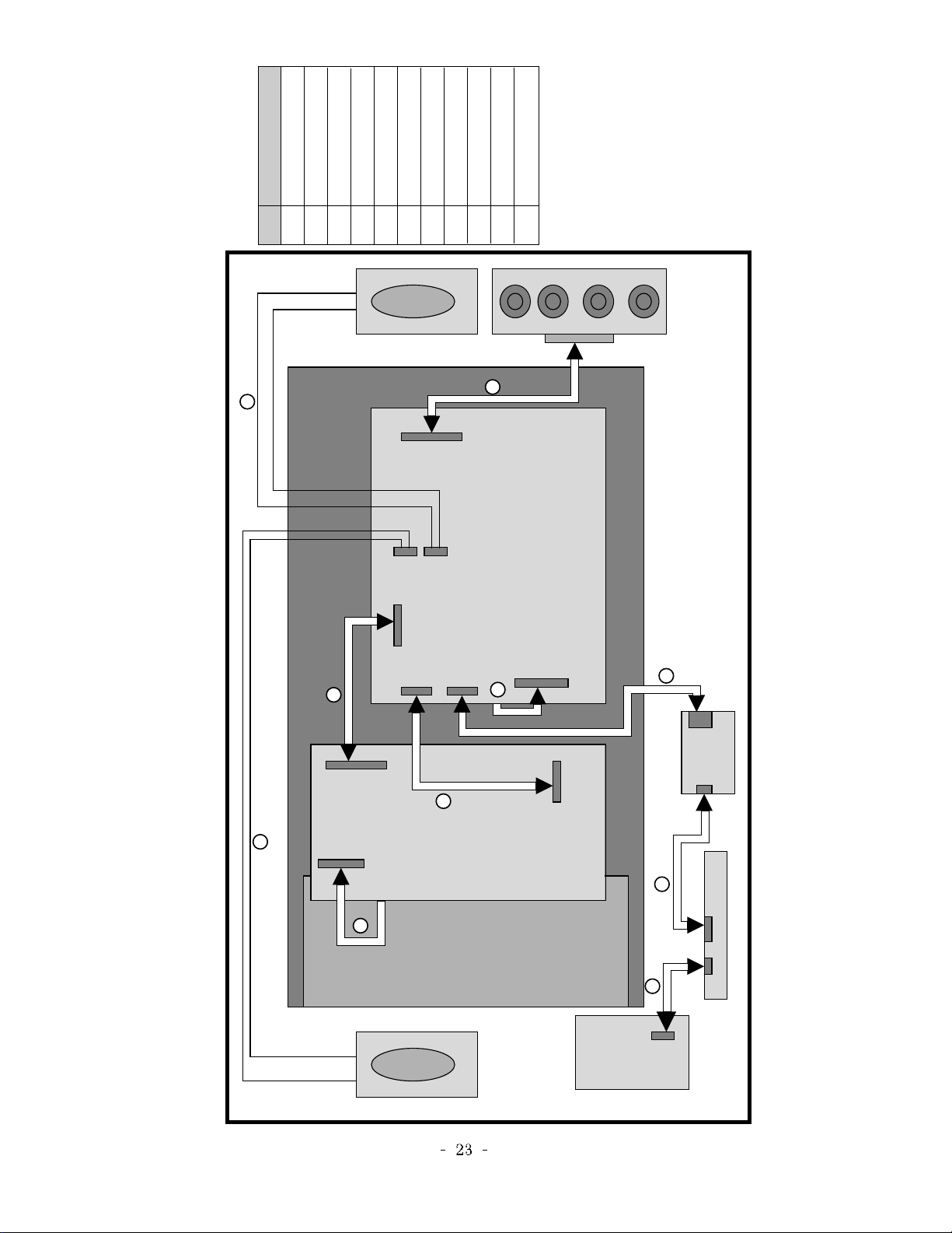
WIRING DIAGRAM
No. Part No.
1
2
3
4
5
6
7
8
9
10
Wiring Part List
6631T11020A -LPL
6631T11020B -AUO
6631T20033F
6631T20032A
6631T25019K
6631T20033B
6631T20033C
6631T20033D
6631T20029Z
6631T20029Y
6631T20033E
SPK
9
8
10
P202
P105
P104
MAIN BORAD
P1100
P101
4
P750
2
P802
1
OARD
5
POWER B
3
SPK
6
P1601P1602
7
Page 24
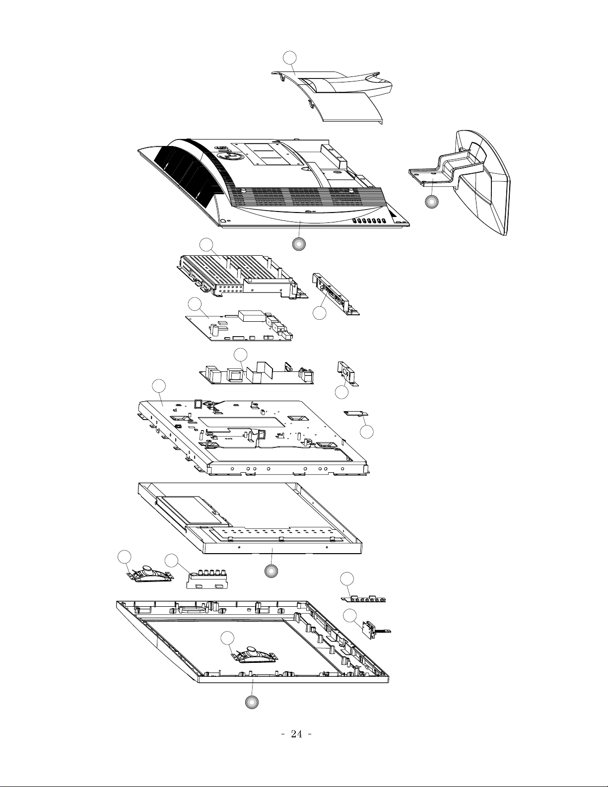
EXPLODED VIEW
15
4
8
12
14
3
13
9
11
10
16
5
2
17
1
7
6
Page 25
Page 26
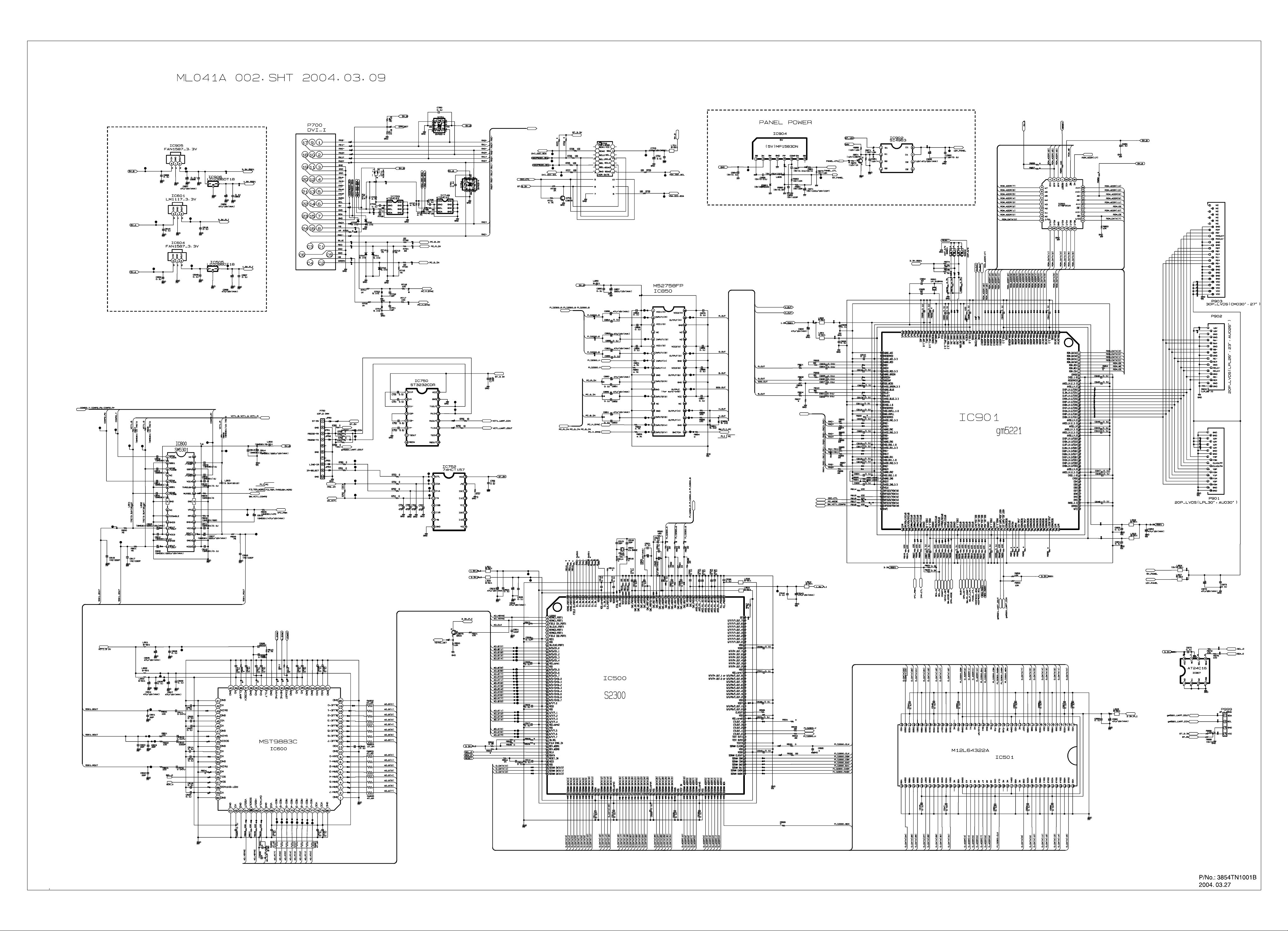
Page 27

Apr., 2004
Printed in KoreaP/NO : 3828TSL101X
 Loading...