

Page 1
3714 Kinnear Place Saskatoon, SK Canada S7P 0A6 Ph: (306) 373-5505 Fx: (306) 374-2245 www.littelfuse.com/relayscontrols
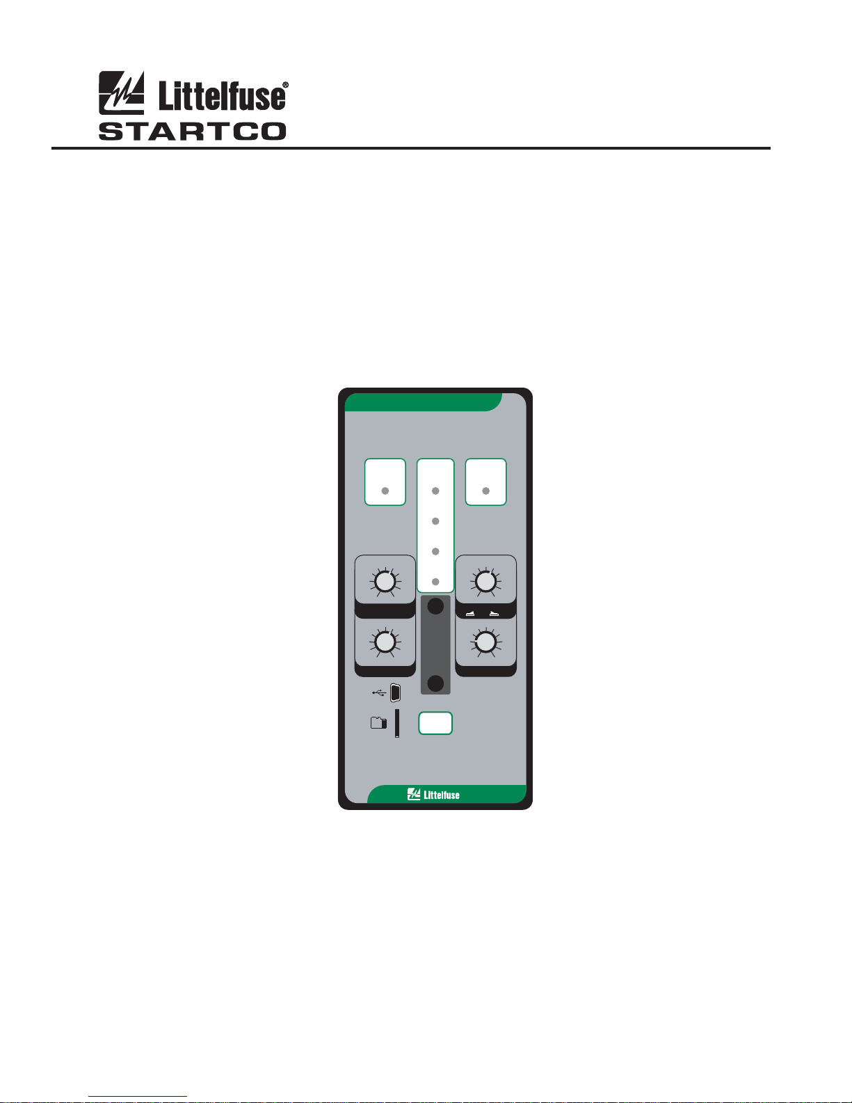
SE-330 MANUAL
NEUTRAL-GROUNDING-RESISTOR MONITOR
REVISION 10-D-112913
LITTELFUSE STARTCO
MONITOR
SE-330NEUTRAL-GROUNDING-RESISTOR
Document Number: PM-1200-EN
Printed in Canada.
GROUND
FAULT
10
8
680
4
GF TRIP LEVEL
(% CT RATING)
0.5
0.4
0.3
0.2
0.1
GF TRIP TIME (s)
TRIP
DIAGNOSTIC
CALIBRATED
RELAY K1
20
40
60
POWER
100
MEM2
0.7
1.0
2.0
3.0
5.0
10.0
RESET
RESISTOR
FAULT
TRIP
200
170
340
130
100 1200
60
200020
V TRIP LEVEL
N
20 K
Ω
100 K
S5
()
N
Vx 1
Vx 5
2.0
1.8
CAL
2.2
1.6
1.4
1.2
1.0
3.0
PULSE PERIOD (s)
800
1700
N
2.4
2.6
2.8
Ω
Copyright 2013 Littelfuse Startco
All rights reserved.
Page 2

Page i
SE-330 Neutral-Grounding-Resistor Monitor Rev. 10-D-112913
This page intentionally left blank.
Page 3

Page ii
TABLE OF CONTENTS
SECTION PAGE
1. General ................................................................. 1
1.1 Modern Resistance-Grounded Systems ................ 1
1.2 SE-330 NGR Monitoring ...................................... 1
2. Operation ............................................................. 2
2.1 Settings .................................................................. 2
2.1.1 GF Trip Time ............................................. 2
2.1.2 GF Trip Level ............................................ 2
2.1.3 V
2.1.4 Pulse-Period Adjustment ........................... 3
2.1.5 Configuration Settings ............................... 3
2.1.5.1 Relay K1 Function (S1) ................ 4
2.1.5.2 Trip-Relay Mode and
Trip-Memory Mode (S2) ........................... 4
2.1.5.3 Ground-Fault-Trip Latch (S3) ....... 4
2.1.5.4 Resistor-Fault-Trip Latch (S4) ...... 4
2.1.5.5 Sensing-Resistor Selection (S5) .... 4
2.1.5.6 Frequency (S6) .............................. 4
2.1.5.7 Upgrade Mode (S8) ....................... 4
2.2 Calibration ............................................................. 4
2.3 Pulsing Operation .................................................. 5
2.4 Trip Indication and Reset ...................................... 5
2.5 Remote Operation ................................................. 5
2.6 Relay K1 LED ....................................................... 5
2.7 Unit Healthy Output .............................................. 5
2.8 Diagnostic LED..................................................... 5
2.9 Analog Output ....................................................... 6
3. Installation ........................................................... 6
3.1 SE-330 .................................................................. 6
3.2 Sensing Resistor .................................................. 12
3.3 Ground-Fault CT ................................................. 20
3.4 Isolated Ground Connection ............................... 25
3.5 Pulsing Connection ............................................. 25
4. Data Interfaces .................................................. 26
4.1 SD Card ............................................................... 26
4.1.1 Datalogging .............................................. 26
4.1.2 Firmware Upgrade ................................... 26
4.2 USB Interface ...................................................... 26
4.3 Network Communications .................................. 26
5. Troubleshooting ................................................ 27
6. Technical Specifications.................................... 28
6.1 SE-330 ................................................................ 28
6.2 Sensing Resistors ................................................ 29
6.3 Current Sensors ................................................... 30
7. Ordering Information ....................................... 31
8. Warranty ........................................................... 32
9. Test Procedures ................................................. 33
9.1 Resistor-Fault Tests ............................................. 33
9.1.1 Calibration and Open Test ....................... 33
9.1.2 Voltage Test ............................................. 33
9.2 Sensing-Resistor Test .......................................... 33
9.3 Analog-Output Test ............................................. 33
9.4 Ground-Fault Performance Test .......................... 34
Appendix A SE-330 Revision History ............................. 35
SE-330 Neutral-Grounding-Resistor Monitor Rev. 10-D-112913
LIST OF FIGURES
FIGURE PAGE
1 Configuration Switches ............................................ 3
2 Analog-Output Connections ..................................... 6
3 SE-330 Connection Diagram .................................... 7
4 SE-330 Outline and Panel-Mounting Details ........... 8
5 SE-330 Outline and Surface-Mounting Details ........ 9
6 SE-IP65CVR-G Weatherproof Cover Outline ....... 10
7 SE-IP65CVR-G Weatherproof Cover Installation . 11
Trip Level ............................................. 2
N
8 ER-600VC Sensing Resistor .................................. 12
9 SE-MRE-600 Moisture-Resistant Enclosure Outline 13
10 ER-600VC Installed in SE-MRE-600 ...................... 14
11 ER-5KV Sensing Resistor ...................................... 15
12 ER-5WP Sensing Resistor ...................................... 16
13 ER-15KV Sensing Resistor .................................... 17
14 ER-25KV Sensing Resistor .................................... 18
15 ER-35KV Sensing Resistor .................................... 19
16 EFCT-1 Sensitive Ground-Fault Current
Sensor ..................................................................... 21
17 SE-CS30-70 Sensitive Ground-Fault
Current Sensor ........................................................ 22
18 EFCT-26 and SE-CS30-26 Sensitive Ground-
Fault Current Sensors ............................................. 23
19 RK-332 Remote Indication and Reset .................... 24
20 PGA-0520 Analog Percent Current Meter ............. 24
21 Simplified Isolated-Ground Connection ................. 25
22 Simplified Pulsing Connection ............................... 25
23 Ground-Fault-Test Circuits .................................... 34
LIST OF TABLES
TABLE PAGE
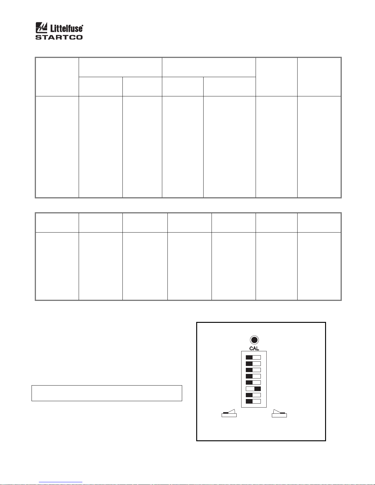
1 Typical Values for Tripping Systems ....................... 3
2 Ground-Fault Trip Levels for Selected CT’s ............ 3
3 Ground-Fault-Test Record ...................................... 34
DISCLAIMER
Specifications are subject to change without notice.
Littelfuse Startco is not liable for contingent or
consequential damages, or for expenses sustained as a result
of incorrect application, incorrect adjustment, or a
malfunction.
Page 4

Page iii
SE-330 Neutral-Grounding-Resistor Monitor Rev. 10-D-112913
This page intentionally left blank.
Page 5

Page 1
SE-330 Neutral-Grounding-Resistor Monitor Rev. 10-D-112913
1. GENERAL
1.1 MODERN RESISTANCE-GROUNDED SYSTEMS
A high-resistance-grounded system uses a neutralgrounding resistor (NGR) with a low let-through current
to limit ground-fault current. This is an improvement
over low-resistance or solidly-grounded systems because,
in those systems, a ground-fault flash hazard exists and a
ground fault can result in substantial point-of-fault
damage. High-resistance grounding eliminates these
problems and modern ground-fault protection operates
reliably at low current levels. Furthermore, the
probability of an arc-flash incident is significantly
reduced in a high-resistance-grounded system.
NGR selection depends on system charging current and
whether the system is an alarm-only or a tripping system.
Alarm-only systems are usually restricted to system
voltages up to 5 kV with NGR let-through currents of 5 A
or less. Occasionally, alarm-only systems up to 15 kV
and up to 10 A are used; however, they are not common
because a ground fault on such a system tends to escalate
to a phase-to-phase fault before the ground fault can be
located and cleared. Consult CEC 10-1102, NEC 250.36,
and NEC 250.186 for application details.
System charging current is the capacitive current that
flows to ground when a bolted ground fault occurs. This
current can be calculated or measured. For small systems,
the magnitude of charging current can be conservatively
estimated as ½ A per 1,000 kVA on low-voltage systems
and 1 A per 1,000 kVA on medium-voltage systems.
In an alarm-only system or in a tripping system without
selective coordination, choose an NGR with a let-through
current larger than the system charging current and set the
pick-up current of ground-fault devices at or below 50%
of the NGR let-through current.
In a tripping system with selective coordination, use
ground-fault devices with a definite-time characteristic to
achieve time coordination. Use the same pick-up current
for all ground-fault devices—this value must be larger
than the charging current of the largest feeder. Select an
NGR with a let-through current between five and 10 times
the pick-up current of the ground-fault devices.
Do not use a grounding transformer with a low-voltage
resistor:
The combined cost of a transformer and a low-
voltage resistor is more than the cost of a resistor
rated for line-to-neutral voltage.
A transformer saturated by a ground fault through a
rectifier can make ground-fault protection
inoperative.
Transformer inrush current up to 12 times rated
current can cause a ground-fault voltage larger than
expected.
A parallel transformer winding makes it difficult to
monitor NGR continuity.
A transformer can provide the inductance necessary
to cause ferroresonance if the NGR opens.
Following these guidelines will reduce the flash hazard,
reduce point-of-fault damage, achieve reliable groundfault protection, and ensure a stable system not subject to
ferroresonance.
1.2 SE-330 NGR M
ONITORING
The SE-330 is a microprocessor-based neutralgrounding-resistor monitor that detects NGR failures and
ground faults in resistance-grounded systems. The
SE-330 measures NGR resistance, NGR current, and
transformer or generator neutral-to-ground voltage. The
components required to monitor an NGR are an SE-330, a
20- or 100-k ER-series sensing resistor, and a current
transformer (CT).
Power-circuit elements, other than neutral-connected
NGR’s, that purposefully connect the power system to
ground are often not compatible with SE-330 NGR
monitoring. These elements include single-phase
grounding transformers, grounded-wye-primary potential
transformers (PT’s), and grounded-wye-primary power
transformers.
The SE-330 continuously measures NGR resistance in
an unfaulted system. It will trip on resistor fault if NGR
resistance varies from its calibrated value. When a
ground fault occurs, voltage is present on the neutral and
NGR current will flow if the NGR is healthy. The
SE-330 will trip on ground fault if fault current exceeds
the GF TRIP LEVEL setting for an interval equal to the
GF TRIP TIME setting. However, if the NGR fails open
during a ground fault, it is possible for fault resistance to
satisfy the NGR resistance measurement. To detect this
double-fault condition, the SE-330 measures neutral
voltage. If neutral voltage exceeds the V
TRIP LEVEL
N
setting and if NGR current is less than 5% of the current
transformer (CT) rating, the SE-330 will trip on resistor
fault. If the resistor-fault circuit is tripped and the neutral
voltage exceeds the V
TRIP LEVEL setting for an
N
interval greater than the GF TRIP TIME setting, the
ground-fault circuit will also trip.
Ground-fault current is sensed by a CT with a 1- or 5-A
secondary, or by a sensitive CT (EFCT-x or
SE-CS30-x) with a 50-mA secondary. The trip level of
the ground-fault circuit is adjustable from 2 to 100% of
the CT rating and trip time is adjustable from 0.1 to 10.0
seconds.
The SE-330 has four output relays. Relay K1 can be
assigned a trip or a pulsing function. Relays K2 and K3
provide ground-fault and resistor-fault indication. K4 is a
solid-state relay that provides UNIT HEALTHY
indication. When relay K1 is assigned the trip function, it
will operate on either a resistor fault or ground fault, and
it can be set to operate in the fail-safe or non-fail-safe
mode for undervoltage or shunt-trip applications. When
Page 6
Page 2
SE-330 Neutral-Grounding-Resistor Monitor Rev. 10-D-112913
the pulsing function is selected, relay K1 is used to
control a contactor to assist in locating faults.
Additional features include LED trip indication, trip
memory, front-panel and remote reset, 4-20-mA analog
output, trip event recorder, USB local communications,
microSD™ data logging, and optional network
communications.
The SE-330 provides additional features over the
SE-330 legacy model (revision 04 or less):
When the trip level is set to MEM, the ground-fault
trip setting is defined by an internal non-volatile
memory variable. Range is 2 to 100% in 1%
increments of the CT-primary rating.
Indication relays can be set to fail-safe or non-fail-
safe.
The number of trip records has been increased to 100
and includes date and time stamping.
A microSD™ card interface can be used for long-
term data logging and firmware updates. A
microSD™ card and a microSD-to-SD adapter is
included. See Section 4.1.
For ease of connection to new devices, the RS-232
interface has been replaced by a Mini B USB port.
Dual Ethernet ports are available with support for
fiber-optic and RJ45 interfaces.
The IEC 61850 protocol has been added.
2. OPERATION
2.1 S
ETTINGS
2.1.1 GF TRIP TIME
GF TRIP TIME (definite time) is adjustable from 0.1 to
10.0 seconds. Time-coordinated ground-fault protection
requires this setting to be longer than the trip times of
downstream ground-fault devices.
A trip-time accumulator provides a ground-fault memory
function for detection of intermittent faults. The
accumulated time increases when a ground fault is detected
and decreases when a ground fault is not detected. A trip
will eventually occur when the time for fault current above
the trip level is greater than the time for fault current below
the trip level.
2.1.2 GF TRIP LEVEL
The SE-330 uses a Discrete-Fourier Transform (DFT)
Algorithm to measure the fundamental component of
NGR current.
Choose an NGR let-through current and a ground-fault
trip level according to the guidelines in Section 1.1. Set the
ground-fault trip level as a percentage (2 to 100) of the CTprimary rating. When the GF Trip Level is set to MEM, the
ground-fault setting stored in non-volatile memory is used.
This parameter must be set using a PC running
SE-MON330 (version 3.0 or newer) connected to the USB
interface. The setting range is 2 to 100% of CT primary
rating in 1% increments. The default value is 15%. Inputs
are provided for 5-, 1-, and 0.05-A-secondary CT’s. Typical
values for 5-, 15-, and 25-A tripping systems are shown in
Table 1. Ground-fault trip levels for selected CT’s are
shown in Table 2. For other systems, refer to the NGR
Monitor Set-Point Assistant at
www.littelfuse.com/relayscontrols. The Set-Point Assistant
is included with SE-MON330.
2.1.3 V
The SE-330 uses a DFT algorithm to measure the
fundamental component of neutral voltage (V
If neutral voltage is greater than the V
setting for 12 s and ground-fault current is less than 5% of
the CT rating, the SE-330 will trip on resistor fault. If the
resistor-fault circuit is tripped and the neutral voltage
exceeds the V
than the GF TRIP TIME setting, the ground-fault circuit
will also trip.
The V
S5 in the 20-k (Vx1) position, and the range is 100 to
10,000 V with switch S5 in the 100-k (Vx5) position.
Calculate the voltage across the NGR when NGR current is
equal to the pick-up current of the ground-fault circuit. Set
the V
and Section 2.1.5.5.
Typical values for 5-, 15-, and 25-A tripping systems are
shown in Table 1. For an NGR resistance greater than 2
k, use a 100-k sensing resistor. For other systems, refer
to the NGR Monitor Set-Point Assistant at
www.littelfuse.com/relayscontrols.
N
OTE: A resistor-fault trip is held off if the ground-fault
current is above 5% of the CT rating.
TRIP LEVEL
N
).
N
TRIP LEVEL
N
TRIP LEVEL setting for an interval greater
N
TRIP LEVEL range is 20 to 2,000 V with switch
N
TRIP LEVEL at the next largest value. See Fig. 1
N
Page 7
Page 3
SE-330 Neutral-Grounding-Resistor Monitor Rev. 10-D-112913
TABLE 1. TYPICAL VALUES FOR TRIPPING SYSTEMS
SYSTEM
VOLTAGE
(VOLTS)
480
600
2,400
4,160
480
600
2,400
4,160
7,200
14,400
4,160
7,200
14,400
25,000
35,000
GF TRIP
(1)
LEVEL
(%)
2
4
6
8
10
20
40
60
80
100
(1)
When set to MEM, range is 2 to 100% in 1% increments.
* Setting not recommended.
2.1.4 P
ULSE-PERIOD ADJUSTMENT
Pulse period is the cycle time of relay K1 when the
SE-330 is configured for pulsing operation. Pulse period
is adjustable from 1.0 to 3.0 seconds with a fixed duty
cycle of 50%. For example, with the 1.0-s setting, relay
K1 will alternately be energized for 0.5 seconds and deenergized for 0.5 seconds when pulsing is enabled.
See Section 2.3 for detailed pulsing operation
information.
N
OTE: For pulsing configuration, set switch S1 to K1 =
PULSING and install an external pulse-enable switch.
2.1.5 C
ONFIGURATION SETTINGS
Eight configuration switches (S1 to S8) and a
calibration button are located behind the access cover on
the front panel. See Fig. 1.
NEUTRAL-GROUNDING
RESISTOR
CURRENT
(AMPERES)
5
5
5
5
15
15
15
15
15
15
25
25
25
25
25
RESISTANCE
(OHMS)
55
69
277
480
18
23
92
160
277
554
96
166
332
577
808
TABLE 2. GROUND-FAULT TRIP LEVELS FOR SELECTED CT’S
EFCT-x
5:0.05
(AMPERES)
SE-CS30-x
(AMPERES)
0.10
0.20
0.30
0.40
0.50
1.00
2.00
3.00
4.00
5.00
30:0.05
0.60
1.20
1.80
2.40
3.00
6.00
12.0
18.0
24.0
30.0
SENSING RESISTOR GROUND-
MODEL RESISTANCE
(SWITCH S5
SETTING)
ER-600VC
ER-600VC
ER-5KV
ER-5KV
ER-600VC
ER-600VC
ER-5KV
ER-5KV
ER-15KV
ER-15KV
ER-5KV
ER-15KV
ER-15KV
ER-25KV
ER-35KV
20 k
20 k
20 k
20 k
20 k
20 k
20 k
20 k
100 k
100 k
20 k
100 k
100 k
100 k
100 k
50:1
50:5
(AMPERES)
*
*
*
*
5
10
20
30
40
50
LATCHING GF TRIP
LATCHING RF TRIP
NOTE:
1. DEFAULT SETTINGS SHOWN.
100:1
100:5
(AMPERES)
*
*
*
8
10
20
40
60
80
100
K1 = TRIP
K1 FAIL-SAFE
20 kΩ
50 Hz
NOT USED
RUN
FIGURE 1. Configuration Switches.
FAULT
TRIP LEVEL
(AMPERES)
1.0
1.0
1.0
1.0
3.0
3.0
3.0
3.0
3.0
3.0
5.0
5.0
5.0
5.0
5.0
200:1
200:5
(AMPERES)
*
*
12
16
20
40
80
120
160
200
CALIBRATION BUTTON
K1 = PULSING
S1
K1 NON-FAIL-SAFE
S2
S3
NON-LATCHING GF TRIP
S4
NON-LATCHING RF TRIP
100 kΩ
S5
60 Hz
S6
S7
UPGRADE
S8
VN TRIP
LEVEL
(VOLTS)
60
100
340
800
60
100
340
800
170x5=850
340x5=1,700
800
170x5=850
340x5=1,700
800x5=4,000
1,200x5=6,000
400:1
400:5
(AMPERES)
*
16
24
36
40
80
160
240
320
400
Page 8
Page 4
SE-330 Neutral-Grounding-Resistor Monitor Rev. 10-D-112913
2.1.5.1 RELAY K1 FUNCTION (S1)
Set switch S1 to K1 = TRIP to assign the trip function
to relay K1 and to activate switch S2. Relay K1 will
change state when a resistor-fault or ground-fault trip
occurs.
Set switch S1 to K1 = PULSING to configure relay K1
for pulsing operation. See Section 2.3.
2.1.5.2 T
RIP-RELAY MODE AND TRIP-MEMORY
MODE (S2)
Set switch S2 to select the operating mode of trip relay
K1. In the non-fail-safe mode, relay K1 energizes and its
contact closes when a trip occurs. The non-fail-safe mode
can be used to trip shunt-trip circuit breakers. In the
non-fail-safe mode, SE-330 trips are reset when supply
voltage is cycled.
In the fail-safe mode, relay K1 energizes and its contact
closes if there are no trips. Contacts open if there is a trip,
a loss of supply voltage, or a processor failure. In the
fail-safe mode, SE-330 trips are not reset when supply
voltage is cycled.
N
OTE: Switch S2 does not affect the operating modes of
relays K2, K3, and K4.
N
OTE: Switch S2 only affects relay K1 operating mode
when K1 is assigned the trip function (switch S1 set to K1
= TRIP). Trip memory is enabled when K1 is set to the
fail-safe mode, regardless of the switch S1 setting.
2.1.5.3 G
ROUND-FAULT-TRIP LATCH (S3)
Set switch S3 to select latching or non-latching groundfault-circuit operation. Non-latching operation defeats
ground-fault-trip memory. See Sections 2.1.5.2 and 2.4.
2.1.5.4 R
ESISTOR-FAULT-TRIP LATCH (S4)
Set switch S4 to select latching or non-latching
resistor-fault-circuit operation. Non-latching operation
defeats resistor-fault-trip memory. See Sections 2.1.5.2
and 2.4
2.1.5.5 S
ENSING-RESISTOR SELECTION (S5)
Set switch S5 to the resistance of the sensing resistor. For
the ER-600VC, ER-5KV, and ER-5WP, select 20 k. For
the ER-15KV, ER-25KV, and ER-35KV, select 100 k.
Switch S5 sets the resistor-fault trip value and the V
TRIP
N
LEVEL range. See Section 2.1.3.
2.1.5.6 F
REQUENCY (S6)
Set switch S6 to 50 or 60 Hz to tune the digital filter to
the line frequency of the monitored system.
2.1.5.7 U
PGRADE MODE (S8)
The microSD™ card is used for firmware upgrades.
See Section 4.1.2 for upgrade instructions.
OTE: An upgrade causes an SE-330 restart and this may
N
cycle the output relays.
2.2 CALIBRATION
The SE-330 measures the resistance change of the
NGR relative to the NGR-resistance value determined at
the time of calibration. When the resistance change is
greater than a threshold amount (500 Ω for 20-kΩ
systems, 2,500 Ω for 100-kΩ systems), a resistor-fault trip
occurs. Calibrate the SE-330 on new installations, if the
NGR is changed, or if the sensing resistor is changed.
N
OTE: If the SE-330 is not calibrated and is supplied
from the load side of the breaker (non-fail-safe mode),
calibrate within 12 seconds of power-up or it may trip and
interrupt its supply.
The CALIBRATION button is located behind the
access cover on the front panel, and it is recessed to
prevent inadvertent activation.
N
OTE: Calibration must be performed with the SE-330
connected to the sensing resistor and NGR of the installed
system.
To calibrate, press and hold the CALIBRATION button
until the green CALIBRATED LED turns off and returns
to on (if the LED is already off, press and hold until the
LED turns on). Calibration takes approximately two
seconds. If calibration is not successful, a resistor-fault
trip occurs, the RESISTOR FAULT TRIP LED will be
on, the CALIBRATED LED will be off, and the
DIAGNOSTIC LED will flash the calibration-error code.
See Section 2.8.
If latching resistor fault (switch S4) is selected, the
calibration-error code flashes until RESET is pressed
even if the CALIBRATED LED is on.
The calibration value is stored in non-volatile memory.
Page 9

Page 5
SE-330 Neutral-Grounding-Resistor Monitor Rev. 10-D-112913
2.3 PULSING OPERATION
If switch S1 is set to K1 = PULSING, pulsing occurs
when terminal 16 is connected to terminal 17. Relay K1
operates at a 50% duty cycle and cycle time is adjustable
from 1.0 to 3.0 seconds. When terminals 16 and 17 are
not connected, K1 is not energized and its contact is open.
Relay K1 can be used to control a contactor rated for
use at the line-to-neutral voltage. The contactor causes
changes in neutral-to-ground resistance by adding or
shorting portions of the NGR. See Section 3.5. Pulsing
ground-fault current appears as zero-sequence current
upstream from the fault.
Pulsing ground-fault current is distinguishable from
charging current and noise, and it can be traced with a
clip-on ammeter or current probe. If pulsing current is
detected on a cable or conduit, the fault is downstream.
Systematic testing allows faults to be located without
isolating feeders or interrupting loads.
Stop pulsing when a fault is located.
2.4 T
RIP INDICATION AND RESET
Red LED's and indication relays indicate ground-fault
and resistor-fault trips. The indication relays K2 (GF) and
K3 (RF) operate in fail-safe or non-fail-safe mode. The
default is non-fail-safe mode. In this mode, the relays are
energized when a fault occurs. The relay mode setting is
stored in non-volatile memory and can be set using PCinterface SE-MON330 (version 3.0 or newer) software or
network communications.
When a trip occurs with latching operation selected, the
SE-330 remains tripped until reset with the front panel
button or the remote-reset input. See Sections 2.1.5.3 and
2.1.5.4. Terminals 15 and 16 are provided for remote reset
as shown in Fig. 3. The reset circuit responds only to a
momentary closure so that a jammed or shorted button
does not prevent a trip. The front-panel RESET button is
inoperative when terminal 15 is connected to terminal 16.
If non-latching operation is selected, trips and
corresponding indication automatically reset when the
fault clears and power-up trip memory is defeated even
when configuration switch S2 is set to fail-safe. The
maximum automatic reset time is 2.8 s.
The red DIAGNOSTIC LED annunciates latched
calibration-error and remote trips. See Section 2.8.
When supply voltage is applied with switch S2 set to
FAIL-SAFE, the SE-330 returns to its state prior to loss
of supply voltage unless switch S3 or S4 is set to nonlatching. When supply voltage is applied with switch S2
set to NON-FAIL-SAFE, SE-330 trips are reset. When a
local, remote, or network reset is issued, both trip LED's
will flash if they are off.
Resistor-fault-trip reset can take up to one second.
Resistor-fault trip-memory trip can take up to three
seconds after SE-330 power up.
2.5 R
EMOTE OPERATION
Relays K2 and K3 can be used for remote indication,
and terminals 15 and 16 are provided for remote reset.
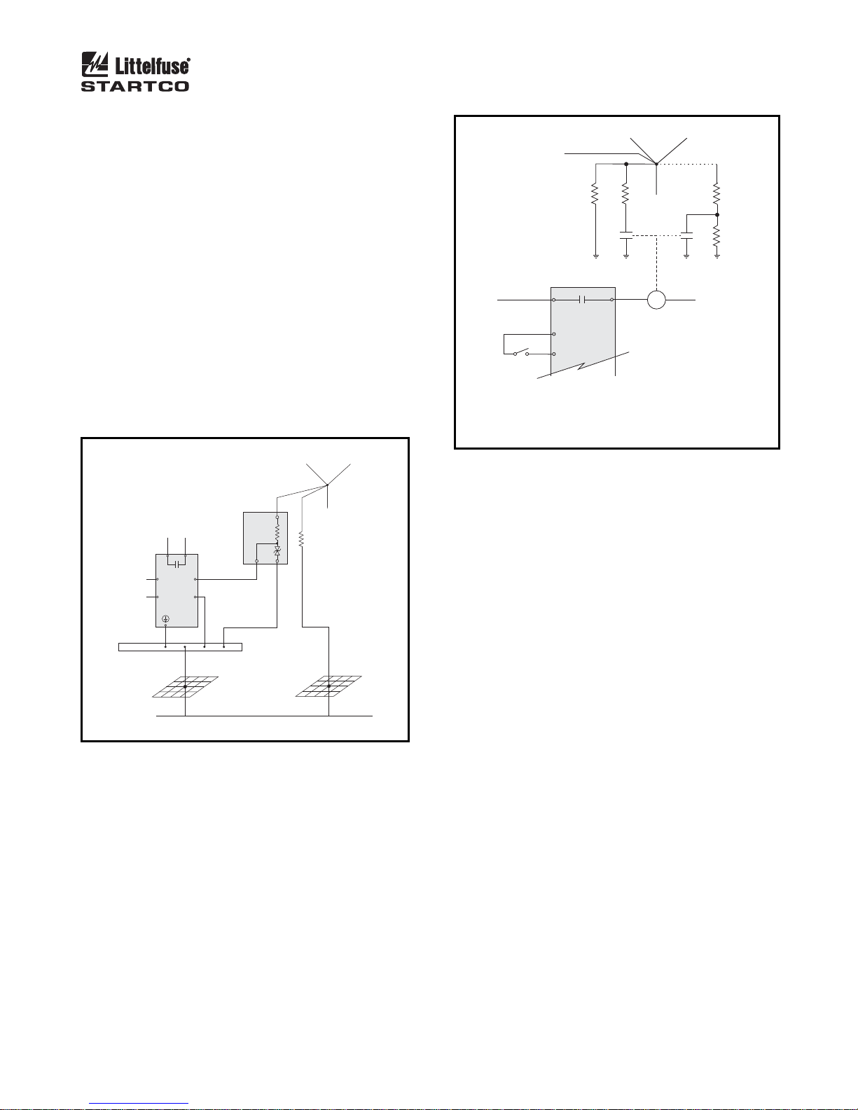
RK-332 Remote Indication and Reset components are
shown in Fig. 19. Connect them as shown in Fig. 3.
RK-332 components are not polarity sensitive.
Indication relays can be set to fail-safe or non-fail-safe
operation using SE-MON330 or network
communications. The default mode is non-fail-safe. In
non-fail-safe mode, relays energize on fault.
Network-enabled SE-330’s can be remotely tripped and
reset by the network master. The red DIAGNOSTIC
LED indicates a network-initiated trip. See Section 2.8.
Refer to the appropriate SE-330 communications manual.
2.6 R
ELAY K1 LED
The yellow RELAY K1 LED follows the state of relay
K1 and is on when K1 is energized (contact closed).
2.7 U
NIT HEALTHY OUTPUT
UNIT HEALTHY relay K4 is energized when the
processor is operating. It can be ordered with N.O. or
N.C. contacts. See Section 7.
N
OTE: The K4 output changes state momentarily during
a processor reset.
N
OTE: K4-contact rating is 100 mA maximum.
IAGNOSTIC LED
2.8 D
The DIAGNOSTIC LED is used to annunciate trips
without individual LED indication. The number of short
LED pulses between pauses indicates the cause of the trip.
See Section 5.
Page 10
Page 6
SE-330 Neutral-Grounding-Resistor Monitor Rev. 10-D-112913
2.9 ANALOG OUTPUT
An isolated 4–20-mA output indicates NGR current
with full-scale output corresponding to the CT rating. An
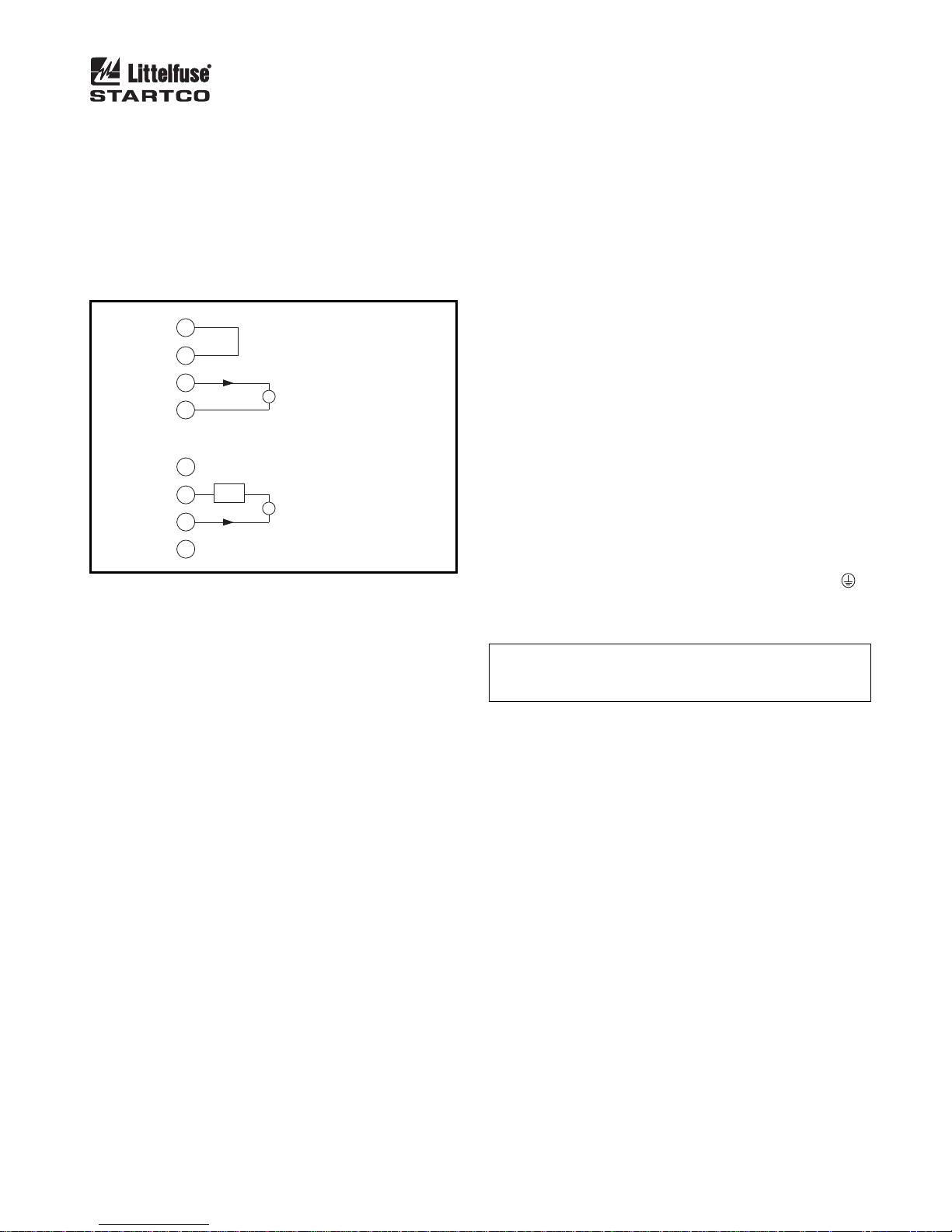
internal 24-Vdc supply allows the analog output to be
connected as a self-powered output. Power from an
external supply is required for loop-powered operation.
See Fig. 2. A PGA-0520 analog meter can be panelmounted to display the NGR current. See Fig. 20 and
Section 7.
18
+24V
+
-
0V
+24V
+
-
0V
19
20
21
18
+
LOOP
SUPPLY
19
20
21
PGA-0520
-
PGA-0520
SELF-POWERED
LOOP POWERED
FIGURE 2. Analog-Output Connections.
3. INSTALLATION
3.1 SE-330
Outline and panel-cutout dimensions for the SE-330 are
shown in Fig. 4. To panel mount the SE-330, insert it
through the panel cutout and secure it with the four
included 8-32 locknuts and flat washers.
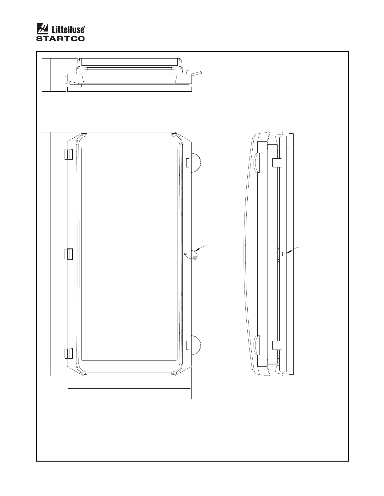
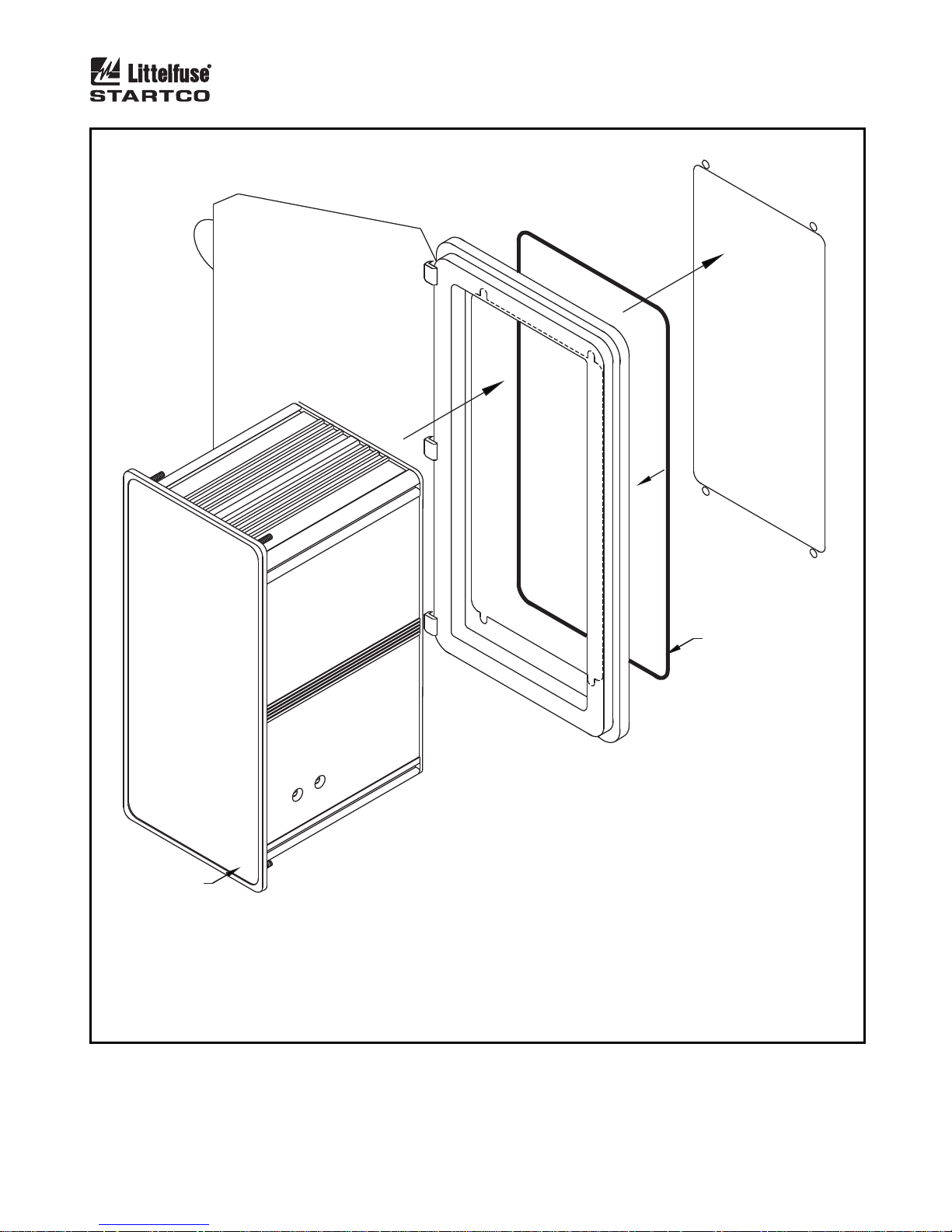
If an optional SE-IP65CVR-G Hinged Cover is used,
follow the included installation instructions. See Figs. 6
and 7.
All connections to the SE-330 are made with plug-in,
wire-clamping terminal blocks. Each plug-in terminal
block can be secured to the SE-330 by two captive screws
for reliable connections.
Outline dimensions and mounting details for surface
mounting the SE-330 are shown in Fig. 5. Fasten the
optional surface-mount adapter to the mounting surface
and make connections to the adapter terminal blocks.
Follow Fig. 5 instructions to mount or remove the SE-
330.
Ground terminal 7 (G) and connect terminal 6 (R) to
the sensing-resistor R terminal.
Use terminal 1 (L1) as the line terminal on ac systems,
or the positive terminal on dc systems. Use terminal 2
(L2/N) as the neutral terminal on ac systems or the
negative terminal on dc systems. Connect terminal 3 (
to ground. Connect terminal 4 (SPG) to terminal 5
(SPGA).
N
OTE: Disconnect terminal 1 (L1) and terminal 2 (L2/N)
before performing dielectric strength testing of the control
panel.
)
Page 11
Page 7
SE-330 Neutral-Grounding-Resistor Monitor Rev. 10-D-112913
TRANSFORMER
OR GENERATOR
NOTE 1 NEUTRAL
NOTE 16
NOTE 12
XXX:1
OR
8
9
S1
XXX:5
10
5C
11
8910
S
SE-330
ALTERNATE CT
CONNECTIONS
REMOTE
RESET
PULSE
ENABLE
L/+ SUPPLY
NOTE 14
OPTIONAL
NETWORK COM
NOTE 10
1
L1
22
26
29
12
UNIT HEALTHY
NC
14
ANALOG OUTPUT
15
RESET
16
PULSE ENABLE
17
3
4
SPG
5
SPGA
R
R
R
G
Y
G
SE-330
INDICATION
GROUND-FAULT
TRIP
RESISTORFAULT TRIP
DIAGNOSTIC
CALIBRATED
RELAY K1
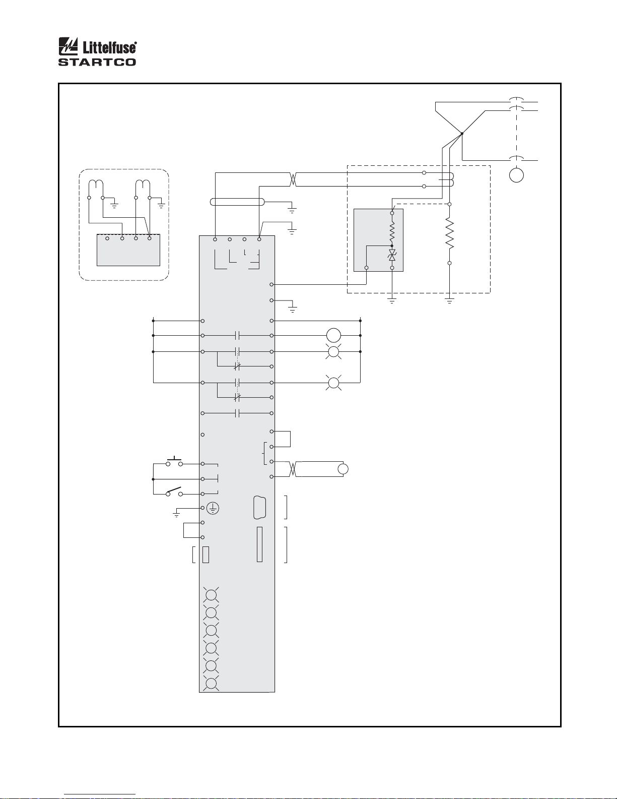
FIGURE 3. SE-330 Connection Diagram.
1
EFCT
NOTE 6
K1
K2
K3
K4
NOTE 7
POWER
1 A
NOTES 11 & 12
ER-SERIES
N/- SUPPLY
C
PGA-0520
SENSING
RESISTOR
11
5
C
5 A
6
R
7
G
2
GF
RF
L2/N
+24V
23
24
25
27
28
13
18
19
+
20
-
21
0V
NOTE 13 & 14
NOTE 8
NOTE 15
GROUND
FAULT
RESISTOR
FAULT
NOTE 2
EFCT-X
OR
SE-CS30-X
NOTE 3
N
NGR
NOTE 4
G
R
NOTE 5
C
NOTES:
1. USE SEPARATE LUG TO CONNECT SENSING RESISTOR TERMINAL N TO NEUTRAL.
2. LOCATE THESE COMPONENTS NEAR
TRANSFORMER OR GENERATOR.
3. ALTERNATE SENSING-RESISTOR
TERMINAL-N CONNECTION. THE NEUTRAL
CONNECTION IS NOT MONITORED.
4. VOLTAGE BETWEEN SENSING-RESISTOR
TERMINALS R AND G IS LIMITED TO 100 V BY
INTERNAL CLAMP.
5. SEE SECTION 3.4 FOR ISOLATED-GROUND
CONNECTION.
6. RELAY CONTACTS SHOWN WITH SE-330
DE-ENERGIZED.
USB PORT
NOTE 9
7. OPTIONAL N.C. K4 AVAILABLE.
8. LOOP-POWERED CONNECTION USES
MICRO SD
SLOT
TERMINALS 19 AND 20 ONLY.
9. MINI B USB DEVICE CONNECTOR.
10. REFER TO APPROPRIATE SE-330
COMMUNICATIONS INTERFACE MANUAL.
11. TWO-CONDUCTOR TWISTED CABLE
REQUIRED, SHIELDED RECOMMENDED.
12. CT CONNECTION IS NOT POLARITY
SENSITIVE.
13. CONNECT CONTACTS K1, K2, K3, AND K4
AS REQUIRED FOR PROTECTION,
INDICATION, AND CONTROL.
14. EXTERNAL LIGHTS AND SWITCHES NOT
INCLUDED WITH SE-330.
15. SELF-POWERED 4-20 mA OUTPUT.
16. TYPICAL TRIPPING SYSTEM.
Page 12
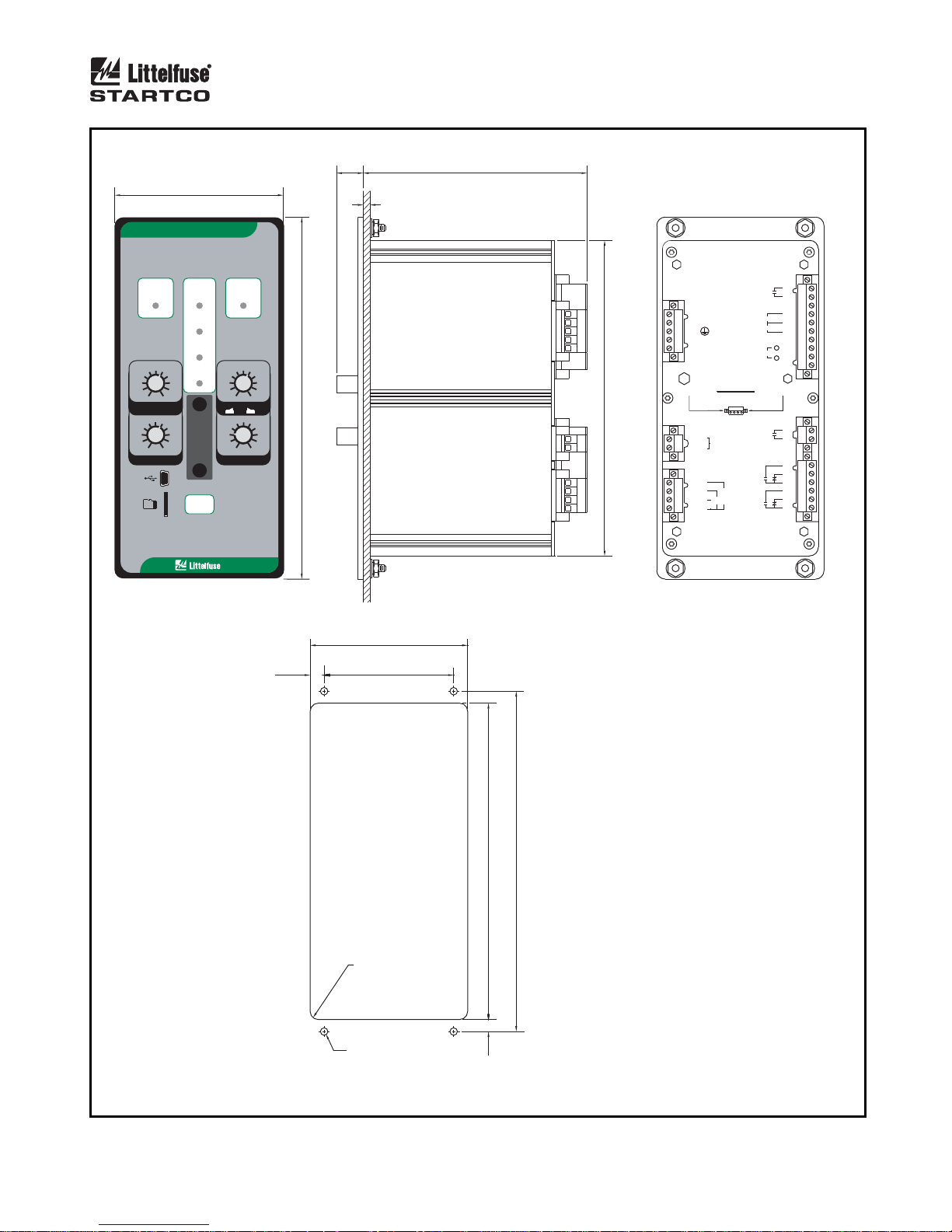
Page 8
SE-330 Neutral-Grounding-Resistor Monitor Rev. 10-D-112913
98.3
(3.87)
LITTELFUSE STARTCO
MONITOR
GROUND
FAULT
DIAGNOSTIC
TRIP
CALIBRATED
RELAY K1
20
10
40
8
60
680
4
GF TRIP LEVEL
(% CT RATING)
0.5
0.4
0.3
0.2
0.1
GF TRIP TIME (s)
POWER
100
MEM2
0.7
1.0
CAL
2.0
3.0
5.0
10.0
RESET
FRONT VIEW
SE-330NEUTRAL-GROUNDING-RESISTOR
RESISTOR
FAULT
TRIP
200
170
340
130
800
100 1200
60
1700
200020
V TRIP LEVELN
20 K
Ω
()
S5
Vx 1
N
2.0
1.8
2.2
1.6
1.4
1.2
1.0
PULSE PERIOD (s)
212.6
Ω
100 K
Vx 5
N
2.4
2.6
2.8
3.0
(8.37)
16.0
(0.63)
132.0
(5.20)
PANEL THICKNESS
1.6 (0.06) TO 4.8 (0.19)
SIDE VIEW
185.4
(7.30)
UNIT
K4
HEALTHY
-
1
L1
-
2
L2/N
-
3
-
4
SPG
-
SPGA
5
DISENGAGE CAPTIVE RETAINING
SCREWS BEFORE REMOVING
PLUG-IN TERMINAL BLOCKS
-
R
6
-
G
7
-
S
8
-
1
9
-
5
10
5
A
-
C
11
PULSE ENABLE
ANALOG OUTPUT
ATTENTION
SENSING
RESISTOR
GROUND
E
F
RESISTOR
C
1
T
A
FAULT
FAULT
RESET
+
K2
K3
REAR VIEW
12
13
-
14
NC
15
16
17
-
24V
18
-
+
19
20
-
-
-
21
0V
22
K1
23
24
25
26
27
28
29
8.2
(0.32)
92.7
(3.65)
76.2
(3.00)
R=4.8 (0.19)
MAXIMUM
4.75 (0.187) DIA
4 LOCATIONS
186.0
7. 0
200.0
(7.32)
(0.28)
NOTES:
1. DIMENSIONS IN MILLIMETRES (INCHES).
(7.87)
PANEL-MOUNT CUTOUT
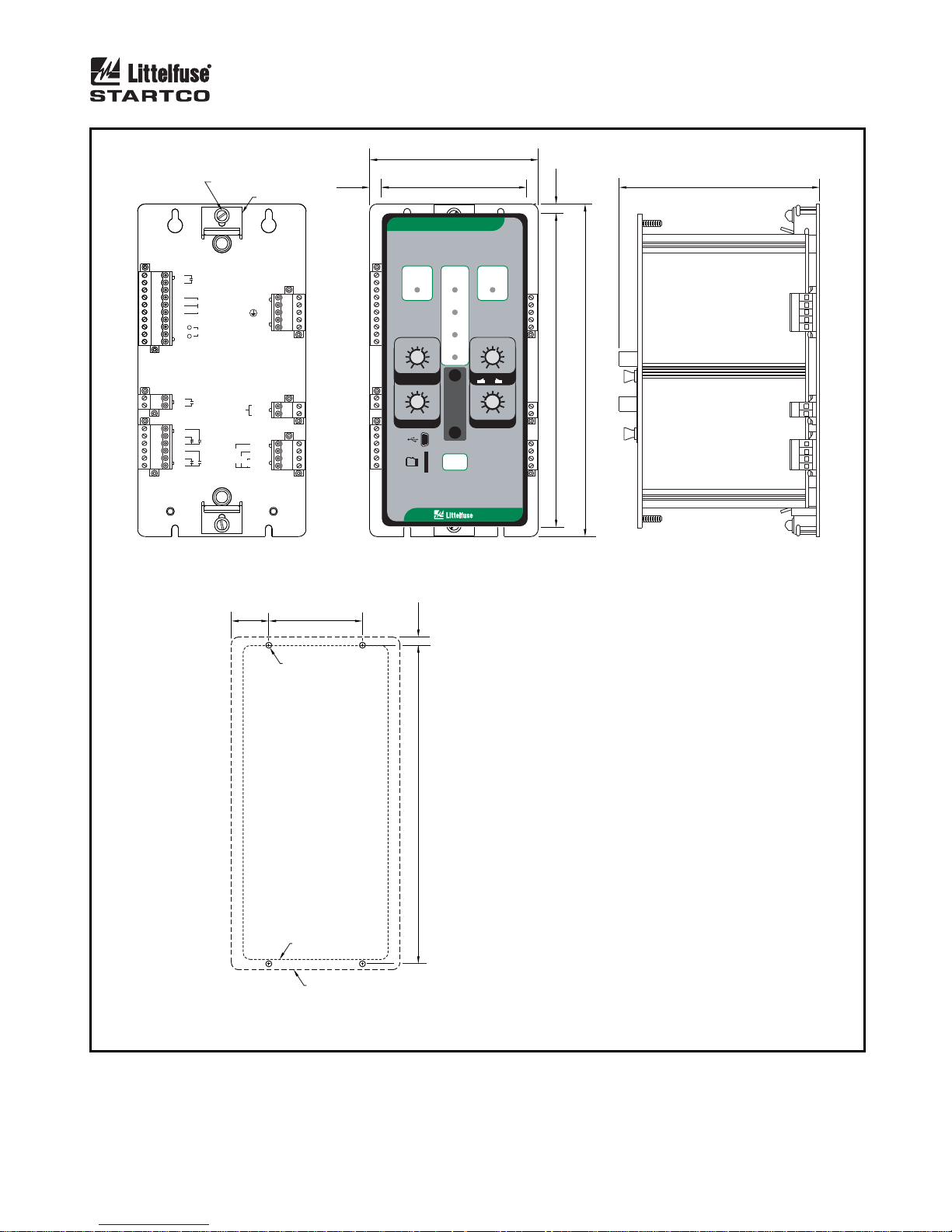
FIGURE 4. SE-330 Outline and Panel-Mounting Details.
Page 13
Page 9
SE-330 Neutral-Grounding-Resistor Monitor Rev. 10-D-112913
114.3
RETAINER SCREW
RETAINER
8.0
(0.31)
(4.50)
98.3
(3.87)
6.4
(0.25)
138.0
(5.43)
12
UNIT
K4
HEALTHY
13
-
14
NC
15
RESET
16
PULSE ENABLE
17
-
24V
18
+
-
+
19
ANALOG OUTPUT
20
-
-
-
0V
21
22
K1
23
24
25
26
27
28
29
GROUND
FAULT
K2
RESISTOR
FAULT
K3
SENSING
RESISTOR
-
L1
-
L2/N
-
-
SPG
-
SPGA
-
R
-
G
-
S
-
E
1
F
C
1
-
5
T
A
5
A
-
C
FRONT VIEW
SE-330-SMA
25.4
(1.00)
LITTELFUSE STARTCO
MONITOR
GROUND
FAULT
DIAGNOSTIC
1 1
2 2
3 3
4 4
5 5
6 6
7 7
8 8
9 9
10 10
11 11
TRIP
CALIBRATED
RELAY K1
20
10
40
8
60
680
4
100
MEM2
GF TRIP LEVEL
(% CT RATING)
0.7
0.5
1.0
0.4
2.0
0.3
3.0
0.2
5.0
0.1
10.0
GF TRIP TIME (s)
POWER
RESET
SE-330NEUTRAL-GROUNDING-RESISTOR
RESISTOR
FAULT
TRIP
200
170
340
130
100 1200
60
V TRIP LEVEL
N
20 K
Ω
S5
()
Vx 1
N
2.0
1.8
CAL
2.2
1.6
1.4
1.2
1.0
PULSE PERIOD (s)
800
1700
200020
Ω
100 K
Vx 5
N
2.4
2.6
2.8
3.0
212.6
(8.37)
225.4
(8.87)
SIDE VIEWFRONT VIEW
63.5
(2.50)
(NOTE 2)
5.0
(0.20)
NOTES:
1. DIMENSIONS IN MILLIMETRES (INCHES).
2. MOUNTING SCREWS: M4 OR 8-32 PANHEAD.
215.9
(8.50)
BEZEL OUTLINE
ADAPTER PANEL OUTLINE
MOUNTING DETAIL
FIGURE 5. SE-330 Outline and Surface-Mounting Details.
INSTALLATION
1. LOOSEN RETAINER SCREWS, MOVE RETAINERS
OUTWARD AND TIGHTEN RETAINER SCREWS.
2. MATE MONITOR WITH ADAPTER PLUG-IN TERMINALS.
LOOSEN RETAINER SCREWS TO LET RETAINERS
SNAP OVER MONITOR BACKPLATE.
3. ENSURE THAT RETAINERS ARE AGAINST MONITOR
BODY AND TIGHTEN RETAINER SCREWS.
REMOVAL
1. LOOSEN RETAINER SCREWS, SLIDE RETAINERS AWAY
FROM MONITOR BODY AND TIGHTEN RETAINER SCREWS.
2. PULL MONITOR FORWARD.
Page 14
Page 10
SE-330 Neutral-Grounding-Resistor Monitor Rev. 10-D-112913
TO PREVENT UNAUTHORIZED ENTRY:
34.0
250.0
(1.34)
(9.84)
TOP VIEW
1. USE WIRE SEAL THROUGH HOLES IN
WEATHERPROOF COVER ASSEMBLY, OR
2. SECURE WITH THE PLASTIC THREAD FORMING
SCREW SUPPLIED IN KIT.
SHOWN
WITH
SEAL
HOLE FOR
SEAL WIRE
127.0
(5.00)
FRONT VIEW SIDE VIEW
NOTES:
1. DIMENSIONS SHOWN IN MILLIMETRES (INCHES).
2. SHOWN WITH WEATHERPROOF SNAPS CLOSED.
3. REFER TO PANEL MOUNTING CUTOUT (FIGURE 4) FOR PANEL
MOUNTING DETAIL.
FIGURE 6. SE-IP65CVR-G Weatherproof Cover Outline.
Page 15
Page 11
SE-330 Neutral-Grounding-Resistor Monitor Rev. 10-D-112913
INSERT THE SE-330 THROUGH OPENING
OF THE WEATHERPROOF WINDOW, UNTIL IT
IS SECURELY NESTED TO THE BACK OF THE
DARK GREY PVC PANEL.
INSTALL O-RING INTO THE GROOVE IN THE REAR
FRONT-PANEL
DETAILS NOT SHOWN.
OF WEATHERPROOF WINDOW ASSEMBLY.
INSERT ASSEMBLY INTO PANEL AND FASTEN WITH
THE HARDWARE PROVIDED WITH THE SE-330.
FIGURE 7. SE-IP65CVR-G Weatherproof Cover Installation.
INSTALL O-RING INTO
GROOVE IN THE REAR
OF WEATHERPROOF
WINDOW
Page 16
Page 12
ER-600VC
SE-330 Neutral-Grounding-Resistor Monitor Rev. 10-D-112913
3.2 SENSING RESISTOR
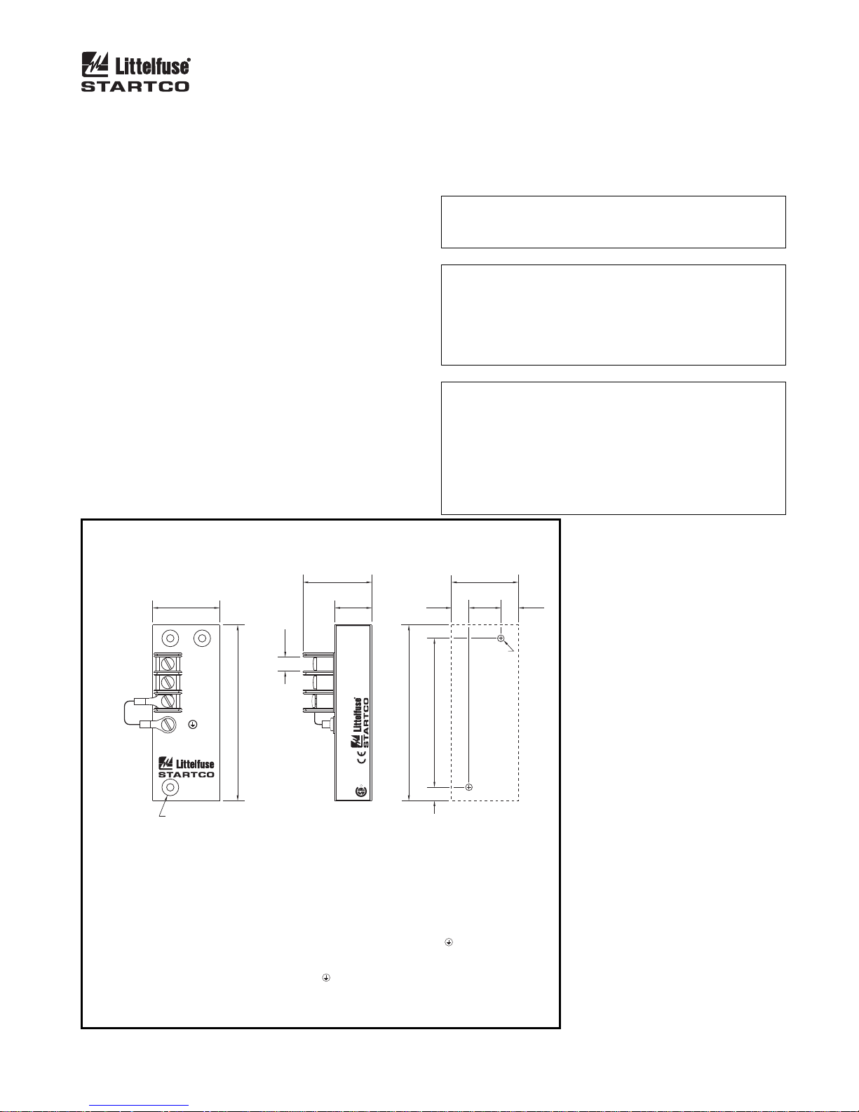
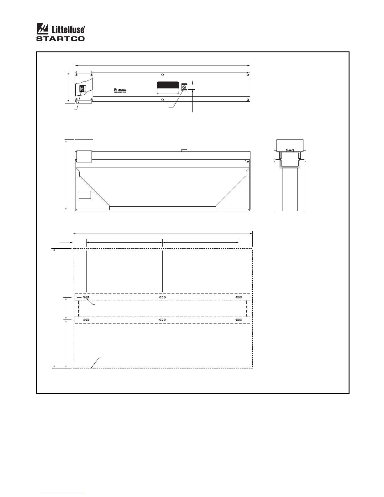
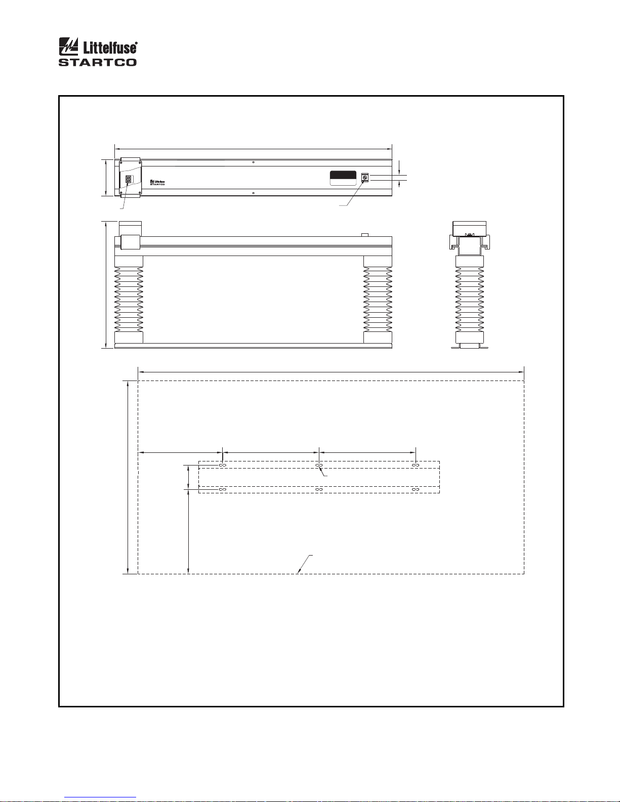
Outline and mounting details for the ER-600VC,
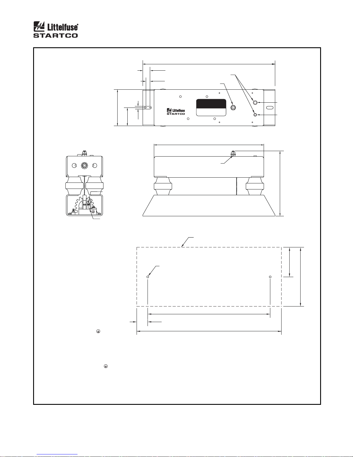
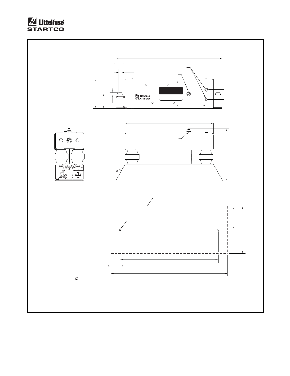
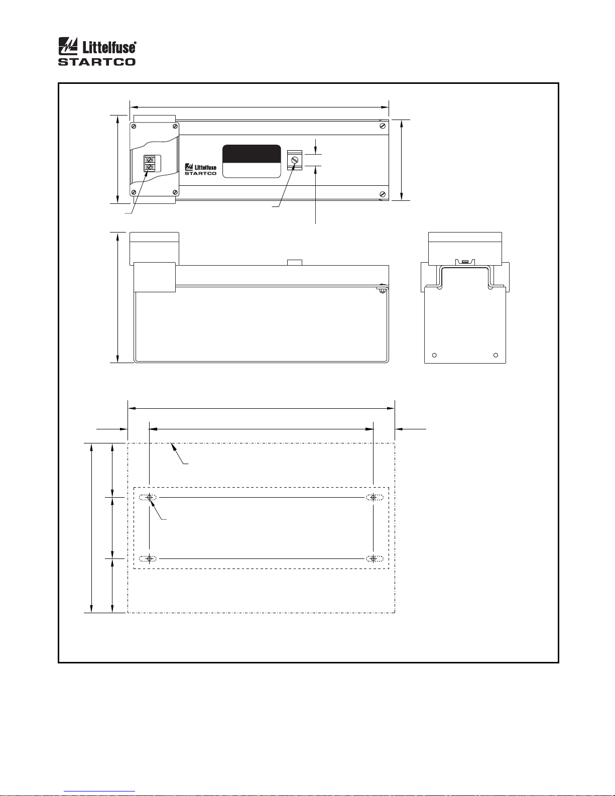
ER-5KV, ER-5WP, ER-15KV, ER-25KV, and ER-35KV
sensing resistors are shown in Figs. 8, 11, 12, 13, 14, and
15. Install the NGR and the sensing resistor near the
transformer or generator. When installed outdoors, a
sensing resistor must be installed in a suitable enclosure.
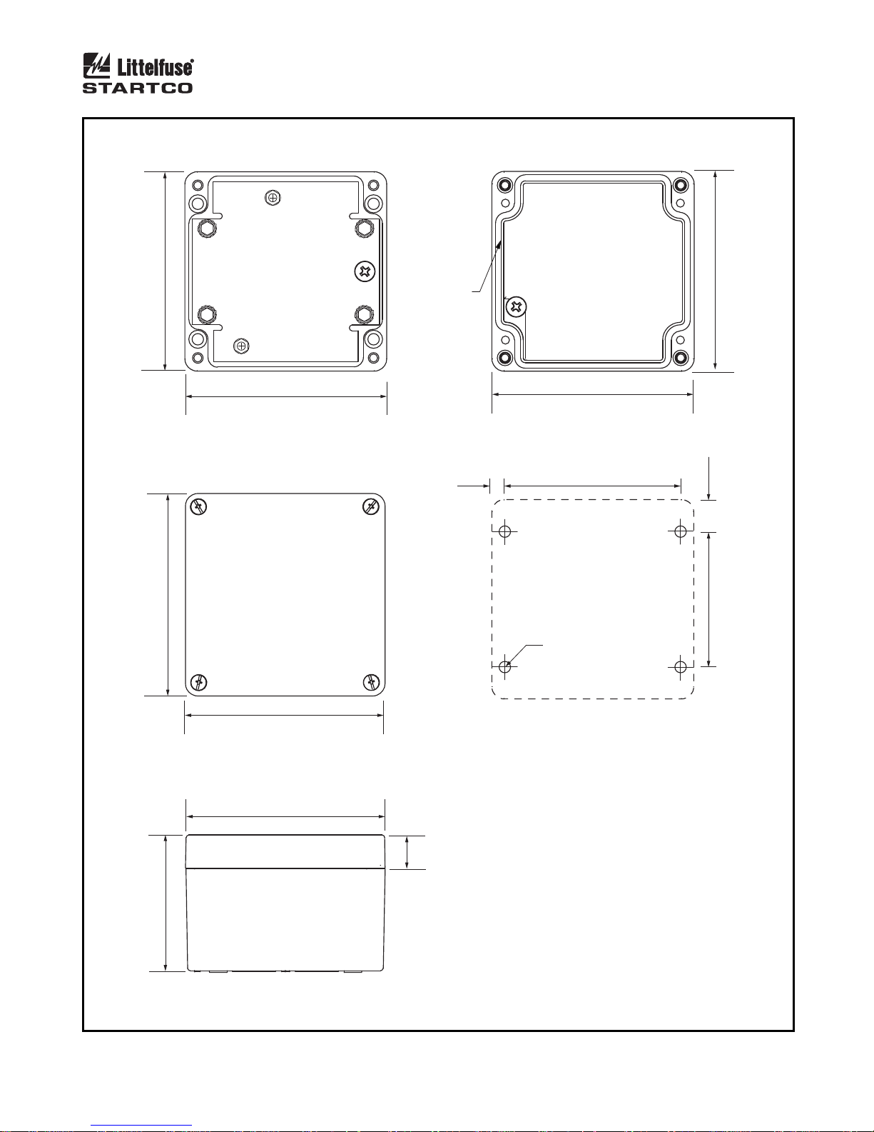
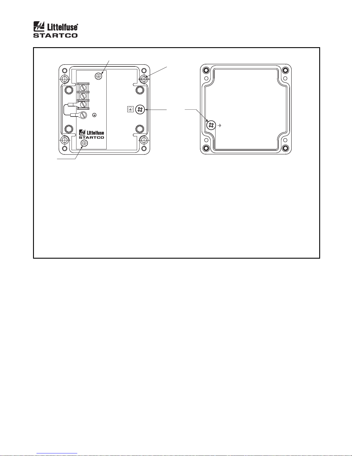
An optional SE-MRE-600 Moisture-Resistant Enclosure
is available for applications which may expose an
ER-600VC to moisture. See Figs. 9 and 10. The
weather-protected ER-5WP shown in Fig. 12 is an
ER-5KV with moisture-resistant terminal covers. Use an
ER-5WP in applications in which it might be exposed to
moisture. The ER-15KV, ER-25KV, and ER-35KV
include moisture-resistant terminal covers. Use suitable
water-tight fittings. Ground sensing-resistor terminal G.
Pass the sensing-resistor-to-neutral conductor and the
NGR-to-neutral conductor through the ground-fault-CT
window as shown in Fig. 3. Separately connect sensingresistor terminal N and the NGR to the neutral to include
neutral connections in the monitored loop. Alternately, if
the NGR connection to system neutral need not be
monitored, connect terminal N to the NGR neutral
terminal.
If a ground fault in the sensing-resistor conductor is
unlikely, a minimal loss of protection will result if it does
not pass through the ground-fault-CT window. See Note 3
in Fig. 3.
N
OTE: Voltage at terminal N rises to line-to-neutral voltage
when a ground fault occurs. The same clearances are
required for sensing resistors as for NGR’s.
N
OTE: A parallel ground path created by moisture can
result in a false resistor-fault trip. Moisture sources
include wind-driven rain or snow, and condensation.
Sensing-resistor terminal R and its connection to SE-330
terminal R, including interposing terminal blocks, must
remain dry.
N
OTE: The neutral-to-sensing-resistor-terminal-N
connection is not a neutral conductor as defined in
Canadian Electrical Code Section 10-1108 and National
Electrical Code Section 250.36(B). It is not required to be
8 AWG (8.36 mm2) or larger. Since current through this
conductor is always less than 250 mA, a 14 AWG
(2.08 mm2) conductor insulated to the system voltage is
more than sufficient.
RATINGS:
MAXIMUM VOLTAGE
MAXIMUM CURRENT
RESISTANCE
THERMAL:
600 Vac 6 MINUTES ON,
420 Vac
.......
..........
..........
ER-600VC
SENSING RESISTOR
600 VAC MAX
600 Vac
.
30 mA
.
20 kΩ
60 MINUTES OFF
CONTINUOUS
40.0
(1.57)
N
R
G
20 K
Ω
4.5 (0.18) DIA
C’BORE 10.0 (0.39) DIA
3.2 (0.13) DEEP
105.0
8.0
(0.31)
(4.13)
FRONT
NOTES:
1. DIMENSIONS IN MILLIMETRES (INCHES).
2. TERMINAL-BLOCK SCREWS: 6-32 x 0.25.
3. MOUNTING SCREWS: M4 OR 8-32.
4. ON REVISION 2 UNITS ENCLOSURE IS ELECTRICALLY CONNECTED TO
TERMINAL G THROUGH JUMPER FROM TERMINAL G TO SCREW.
THIS CONNECTION MAY BE REMOVED FOR DIELECTRIC STRENGTH
TESTING. ENSURE THAT THE JUMPER IS INSTALLED AFTER TESTING.
5. ON REVISION 1 UNITS, SCREW IS NOT PRESENT AND ENCLOSURE IS
ELECTRICALLY CONNECTED TO TERMINAL G.
6. NOT ALL CERTIFICATIONS SHOWN.
FIGURE 8. ER-600VC Sensing Resistor.
41.5
(1.63)
SIDE
22.2
(0.87)
20 KΩ
at 600 Vac
30 mA Max
Continuous at 420 Vac
Duty Cycle: 6 Minutes On, 60 Minutes Off
Rating: 600 Vac 50/60 Hz
GC131105487
SENSING RESISTOR
Serial No:
02
LR 53428
R
Revision:
1-800-TEC-FUSE (1-800-832-3873)
Made in Saskatoon, Canada
ER-600VC
SE-325, SE-330, SE-330AU
Use with:
IEEE 32
US
C
10.5
(0.41)
89.0
(4.13)
105.0
(3.50)
8.0
(0.31)
MOUNTING DETAIL
40.0
(1.57)
19.0
(0.75)
NOTE 3
10.5
(0.41)
Page 17
Page 13
SE-330 Neutral-Grounding-Resistor Monitor Rev. 10-D-112913
(4.80)
122.0
122.0
(4.80)
GASKET
120.4
(4.74)
ENCLOSURE - TOP VIEW
(COVER REMOVED)
122.0
(4.80)
120.4
(4.74)
ENCLOSURE - TOP VIEW
9.5
(0.38)
120.4
(4.74)
COVER - INSIDE VIEW
82.5
(3.25)
M6 OR 0.25-20
MOUNTING DETAIL
(0.75)
(13.25)
19.1
82.5
120.4
(4.74)
84.6
(3.33)
ENCLOSURE - SIDE VIEW
FIGURE 9. SE-MRE-600 Moisture-Resistant Enclosure Outline.
(0.80)
20.4
NOTES:
1. DIMENSIONS IN MILLIMETRES (INCHES).
2. MOUNTING SCREWS: M6 OR 0.25-20.
Page 18
Page 14
SE-330 Neutral-Grounding-Resistor Monitor Rev. 10-D-112913
NOTE 2
MOUNTING
SCREWS
4 LOCATIONS
NOTE 4
N
R
NOTE 2
G
ER-600VC
SENSING RESISTOR
20 K
Ω
600 VAC MAX
ENCLOSURE - TOP VIEW
(COVER REMOVED)
ASSEMBLY INSTRUCTIONS
NOTE 3
COVER - INSIDE VIEW
1. DRILL HOLE FOR ENCLOSURE WIRE ENTRY. USE LIQUID-TIGHT FITTING.
2. REMOVE NYLON NUTS AND WASHERS. INSERT ER-600VC INTO ENCLOSURE. REPLACE NUTS AND WASHERS.
3. ATTACH GROUND WIRE FROM ENCLOSURE TO COVER AND TO ER-600VC TERMINAL G.
4. MOUNT SE-MRE-600 IN PLACE USING M6 OR 0.25-20.
5. COMPLETE OTHER WIRING AND REPLACE COVER.
FIGURE 10. ER-600VC Installed in SE-MRE-600.
Page 19
Page 15
SE-330 Neutral-Grounding-Resistor Monitor Rev. 10-D-112913
RATINGS:
MAXIMUM VOLTAGE
MAXIMUM CURRENT
RESISTANCE
THERMAL
TORQUE
..........
TERMINAL N (3 LOCATIONS)
10-32 INSERT
OTHERS
.
.......
.....
...
.....
2,500 Vac
.
.
125 mA
20 kΩ
CONTINUOUS
5.6 N-m (50 in-lb)
9.0 N-m (80 in-lb)
105.0
NOTE 2
GR
NOTES 5 & 6
SIDE VIEW
NOTES:
1. DIMENSIONS IN MILLIMETRES (INCHES).
381.0
21.0
(0.83)
ALTERNATE NEUTRAL CONNECTION
12.0
(0.47)
NEUTRAL CONNECTION
ER-5KV
SENSING RESI TORS
20 K
Ω
2500 VAC MAX
(4.13)
7. 9
52.5
(2.07)
(0.31)
(15.00)
CAUTION
HIGH VOLTAGE
VOLTAGE ON THIS SURFACE RISES
TO LINE-TO-NEUTRAL VOLTAGE
WHEN A GROUND FAULT OCCURS
0.25-20 UNC
N
N
N
THREADED
INSERT
10-32 THREADED
INSERT
TOP VIEW
316.0
(12.44)
0.25-20 UNC STUD
188.0
(7.40)
FRONT VIEW
MINIMUM DISTANCE
TO ADJACENT OBJECTS
2. TERMINAL-BLOCK SCREWS: 6-32 x 0.25.
3. MOUNTING SCREWS: M6 OR 0.25-20.
4. THIS DEVICE CAN DISSIPATE
300 WATTS. TO MINIMIZE SURFACE
TEMPERATURES FOR SYSTEMS
ALLOWED TO OPERATE
CONTINUOUSLY WITH A GROUND
FAULT, MOUNT VERTICALLY WITH
R & G TERMINALS DOWN.
5. ON REVISION 2 UNITS BASE IS
ELECTRICALLY CONNECTED TO
TERMINAL G THROUGH JUMPER
FROM TERMINAL G TO SCREW.
THIS CONNECTION MAY BE
REMOVED FOR DIELECTRIC
STRENGTH TESTING. ENSURE
THAT THE JUMPER IS INSTALLED
AFTER TESTING.
6. ON REVISION 0 & 1 UNITS SCREW
IS NOT PRESENT AND BASE IS
ELECTRICALLY CONNECTED TO
TERMINAL G.
7. CERTIFICATIONS NOT SHOWN.
FIGURE 11. ER-5KV Sensing Resistor.
NOTE 3
50.7
(2.00)
MINIMUM CLEARANCE FROM BASE
254.0 (10.00)
355.6
(14.00)
457.0
(18.00)
MOUNTING DETAIL
127.0
(5.00)
254.0
(10.00)
Page 20
Page 16
SE-330 Neutral-Grounding-Resistor Monitor Rev. 10-D-112913
RATINGS:
MAXIMUM VOLTAGE
MAXIMUM CURRENT
RESISTANCE
THERMAL
TORQUE
..........
TERMINAL N (3 LOCATIONS)
10-32 INSERT
OTHERS
.
.......
.....
...
.....
2,500 Vac
.
.
125 mA
20 kΩ
CONTINUOUS
5.6 N-m (50 in-lb)
9.0 N-m (80 in-lb)
105.0
(4.13)
NOTE 2 AND 5
SIDE VIEW
NOTES:
1. DIMENSIONS IN MILLIMETRES (INCHES).
2. TERMINAL-BLOCK SCREWS: 6-32 x 0.25
CABLE ACCESS OPENING IS 1/2 NPT.
USE A LIQUID-TIGHT FITTING FOR
CABLE ENTRY.
3. MOUNTING SCREWS: M6 OR 0.25-20.
4. THIS DEVICE CAN DISSIPATE
300 WATTS. TO MINIMIZE SURFACE
TEMPERATURES FOR SYSTEMS
ALLOWED TO OPERATE
CONTINUOUSLY WITH A GROUND
FAULT, MOUNT VERTICALLY WITH
R & G TERMINALS DOWN.
5. BASE IS ELECTRICALLY CONNECTED
TO TERMINAL G THROUGH JUMPER
FROM TERMINAL G TO SCREW.
THIS CONNECTION MAY BE
REMOVED FOR DIELECTRIC
STRENGTH TESTING. ENSURE THAT
THE JUMPER IS INSTALLED AFTER
TESTING.
6. CERTIFICATIONS NOT SHOWN.
FIGURE 12. ER-5WP Sensing Resistor.
52.5
7. 9
(2.07)
(0.31)
21.0
(0.83)
ALTERNATE NEUTRAL CONNECTION
12.0
(0.47)
NEUTRAL CONNECTION
ER-5WP
SENSING RESI TORS
20 K
Ω
2500 VAC MAX
VO LTA GE O N THI S SU RFA CE R IS ES
WHEN A GROUND FAULT OCCURS
HIGH VOLTAGE
TO LINE-TO-NEUTRAL VOLTAGE
TOP VIEW
0.25-20 UNC STUD
FRONT VIEW
MINIMUM DISTANCE
TO ADJACENT OBJECTS
NOTE 3
MINIMUM CLEARANCE FROM BASE
50.7
(2.00)
MOUNTING DETAIL
381.0
(15.00)
CAUTION
316.0
(12.44)
254.0 (10.00)
355.6
(14.00)
457.0
(18.00)
0.25-20 UNC
N
N
N
THREADED
INSERT
10-32 THREADED
INSERT
188.0
(7.40)
127.0
(5.00)
254.0
(10.00)
Page 21
Page 17
SE-330 Neutral-Grounding-Resistor Monitor Rev. 10-D-112913
422.0
RATINGS:
MAXIMUM VOLTAGE
MAXIMUM CURRENT
RESISTANCE
THERMAL
8,400 Vac
132.0
(5.20)
1,900 Vac
TORQUE
TERMINAL N
.......
.
..........
..........
..
.....
8,400 Vac
..
.
84 mA
100 kΩ
1 MINUTE ON,
120 MINUTES
OFF
CONTINUOUS
9.0 N-m (80 in-lb)
.
NOTES 2 AND 4
144.0
215.0
(5.67)
(8.46)
(16.61)
ER-15KV
SENSING RESISTOR
100 K
Ω
R
G
8400 VAC MAX
1MINUTEMAX
CAUTION
HIGH VOLTAGE
VOLTAGE AT TERMINAL N RISES
TO LINE-TO-NEUTRAL VOLTAGE
WHEN A GROUND FAULT OCCURS
N
0.25-20 BINDING HEAD
20.5
TOP
(0.81)
39.5
(1.56)
MINIMUM DISTANCE
TO ADJACENT OBJECTS
90.0
(3.53)
NOTE 3
280.0
100.0
(3.94)
(11.00)
90.0
(3.53)
MINIMUM CLEARANCE FROM BASE
MOUNTING DETAIL
FIGURE 13. ER-15KV Sensing Resistor.
FRONT
444.0
(17.50)
365.0
(14.37)
305.0 (12.00)
SIDE
39.5
(1.56)
NOTES:
1. DIMENSIONS IN MILLIMETRES
(INCHES).
2. TERMINAL-BLOCK SCREWS:
6-32 x 0.25.
3. MOUNTING SCREWS:
M6 OR 0.25-20.
4. USE LIQUID-TIGHT FITTING
FOR TERMINAL-BLOCK ENCLOSURE CABLE ENTRY.
5. CERTIFICATIONS NOT SHOWN.
Page 22
Page 18
SE-330 Neutral-Grounding-Resistor Monitor Rev. 10-D-112913
780.0
(30.70)
RATINGS:
144.0
NOTES 2 AND 4
320.0
(5.67)
(12.60)
ER-25KV
SENSING RESISTOR
100 K
Ω
R
G
14,400 VAC MAX
1MINUTEMAX
0.25-20 BINDING HEAD
CAUTION
CAUTION
HIGH VOLTAGE
HIGH VOLTAGE
VOLTAGE AT TERMINAL N RISES
TO LINE-TO-NEUTRAL VOLTAGE
WHEN A GROUND FAULT OCCURS
TOP
N
20.5
(0.81)
MAXIMUM VOLTAGE
MAXIMUM CURRENT
RESISTANCE
THERMAL
14,400 Vac
2,500 Vac
TORQUE
TERMINAL N
.......
.........
.........
..
.....
.
14,400 Vac
.
144 mA
100 kΩ
1 MINUTE ON,
120 MINUTES
OFF
CONTINUOUS
9.0 N-m (80 in-lb)
534.0
(21.00)
60.0
(2.40)
100.0
217.0
NOTE 3
(3.94)
(8.50)
340.0
(13.38)
MINIMUM CLEARANCE FROM BASE
MINIMUM DISTANCE
TO ADJACENT OBJECTS
FIGURE 14. ER-25KV Sensing Resistor.
FRONT
800.0
(31.50)
508.0 (20.00)
MOUNTING DETAIL
340.0
(13.38)
SIDE
NOTES:
1. DIMENSIONS IN
MILLIMETRES (INCHES).
2. TERMINAL-BLOCK SCREWS:
6-32 x 0.25.
3. MOUNTING SCREWS:
M6 OR 0.25-20
4. USE LIQUID-TIGHT FITTING
FOR TERMINAL-BLOCK ENCLOSURE CABLE ENTRY.
5. MOUNT AS SHOWN
WITH BASE HORIZONTAL.
6. CERTIFICATIONS NOT SHOWN.
Page 23
Page 19
SE-330 Neutral-Grounding-Resistor Monitor Rev. 10-D-112913
132.0
NOTES 2 AND 4
459.0
(5.20)
(18.10)
RATINGS:
MAXIMUM VOLTAGE
MAXIMUM CURRENT
RESISTANCE
20.5
THERMAL
(0.81)
TORQUE
22,000 Vac
3,000 Vac
TERMINAL N
..........
1000.0
(39.40)
ER-35KV
SENSING RESISTOR
100 K
Ω
222,00 VAC MAX
R
1MINUTEMAX
G
0.25-20 BINDING HEAD
CAUTION
HIGH VOLTAGE
VOLTAGE AT TERMINAL N RISES
TO LINE-TO-NEUTRAL VOLTAGE
WHEN A GROUND FAULT OCCURS
N
.......
.........
..
.....
22,000 Vac
.
.
220 mA
100 kΩ
1 MINUTE ON,
120 MINUTES
OFF
CONTINUOUS
9.0 N-m (80 in-lb)
TOP
FRONT SIDE
1600.0
(63.00)
MINIMUM CLEARANCE FROM BASE
685.0 (27.00)
350.0
(13.80)
800.0
(31.50)
100.0
350.0
(13.80)
(3.90)
NOTES:
1. DIMENSIONS IN MILLIMETRES (INCHES).
2. TERMINAL-BLOCK SCREWS: 6-32 x 0.25.
3. MOUNTING SCREWS: M6 OR 0.25-20.
4. USE LIQUID-TIGHT FITTING FOR
TERMINAL-BLOCK-ENCLOSURE CABLE ENTRY.
5. MOUNT AS SHOWN WITH BASE HORIZONTAL.
6. CERTIFICATIONS NOT SHOWN.
FIGURE 15. ER-35KV Sensing Resistor.
400.0
(15.70)
MINIMUM DISTANCE
TO ADJACENT OBJECTS
MOUNTING DETAIL
400.0
(15.70)
NOTE 3
Page 24
Page 20
SE-330 Neutral-Grounding-Resistor Monitor Rev. 10-D-112913
3.3 GROUND-FAULT CT
Select and install a ground-fault CT that will provide
the desired trip level. Typically, the CT-primary rating
should be approximately equal to the NGR let-throughcurrent rating. This provides an appropriate GF TRIP
LEVEL setting range and analog-output scaling. See
Sections 2.1.2 and 2.9.
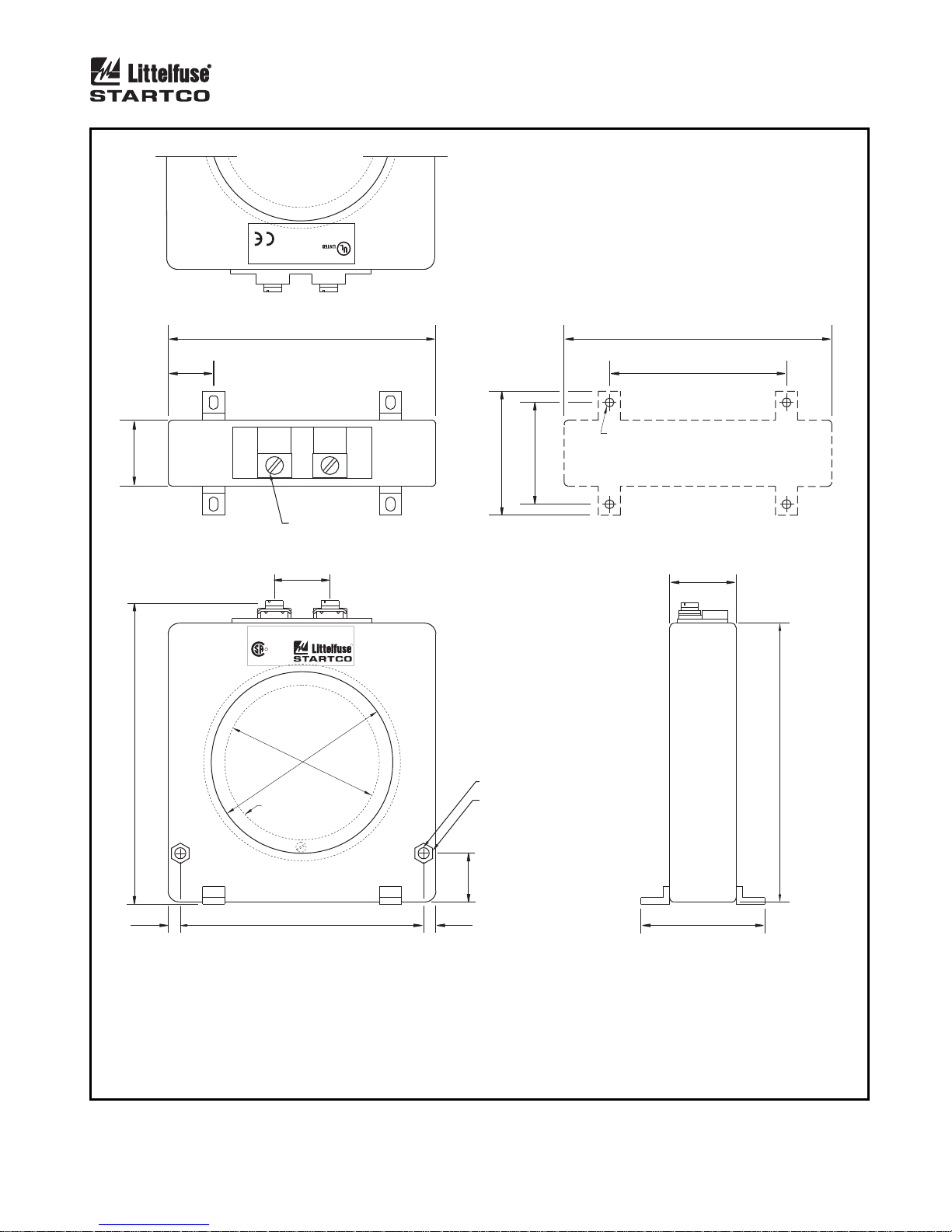
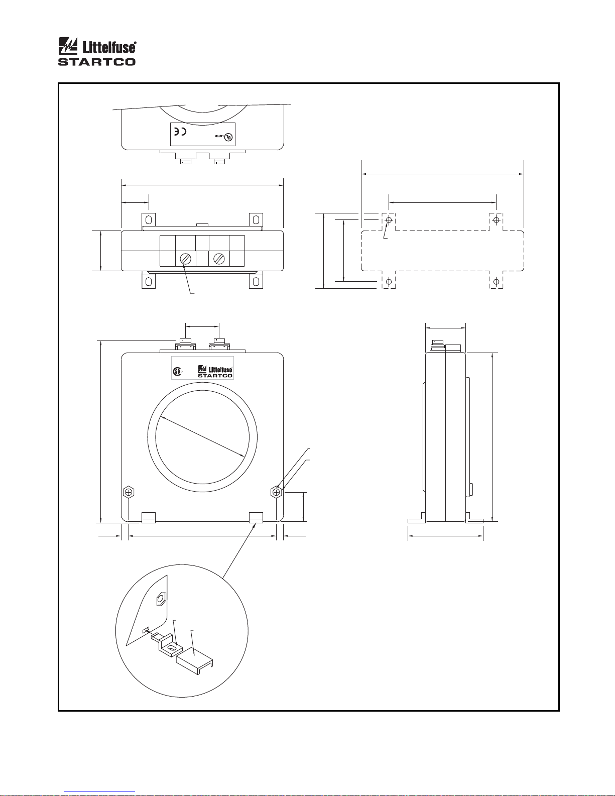
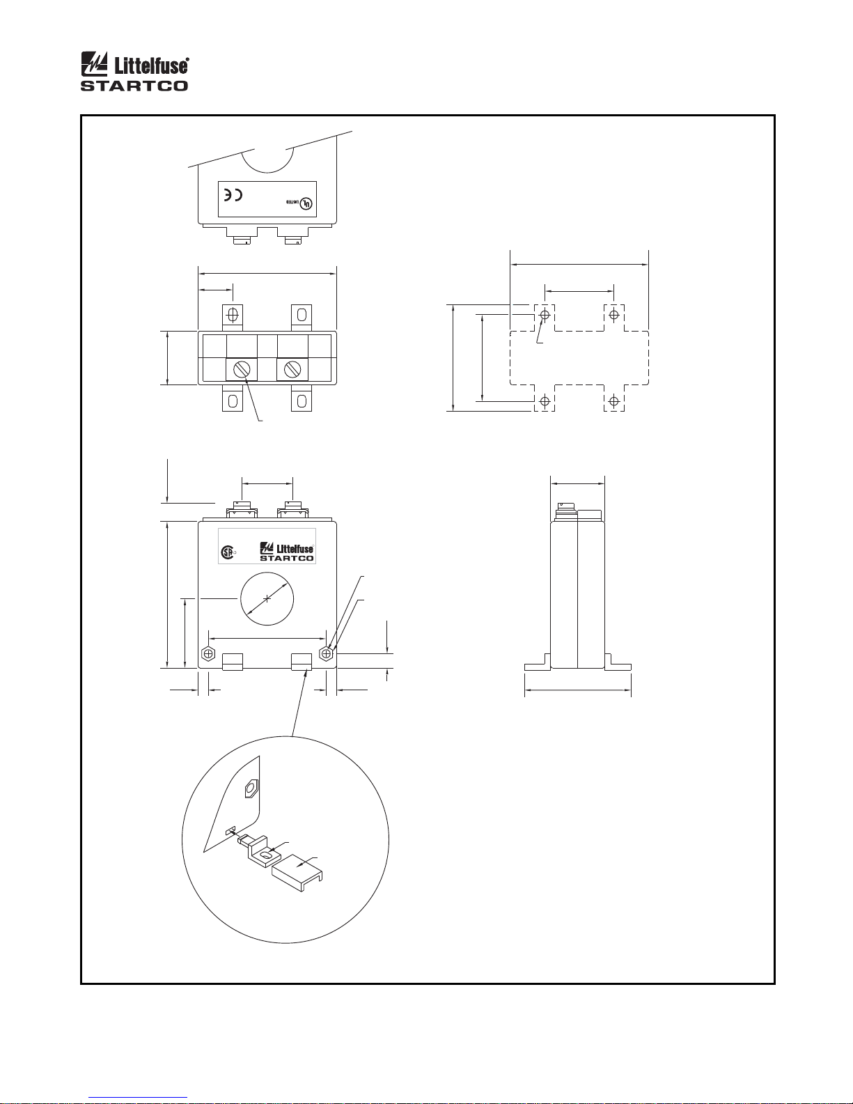
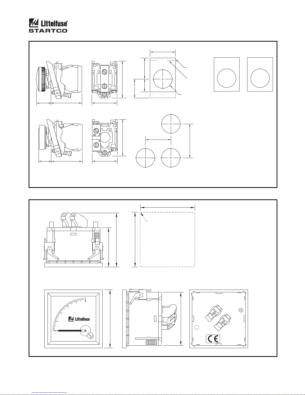
Outline and mounting details for the sensitive EFCTand SE-CS30-series current sensors are shown in Figs.
16, 17, and 18. Ground-fault-CT connections and the
typical ground-fault-CT location are shown in Fig. 3.
For SE-325 replacement applications, the existing
CT200 current sensor will typically have to be replaced.
However, where replacement is not necessary or
possible, the CT200 can be connected to either the 1- or
5-A input. This CT has a 200:5 current ratio. If
connected to the 1-A input, the ground-fault trip level
will be a percentage of 40 A. See Section 2.1.2.
The accuracy of a typical current sensor, including the
CT200, decreases below 5% of its current rating. CTprimary current-injection testing is recommended to
verify trip levels below 5% of the
CT-primary rating. See Section 9.4. Littelfuse Startco
sensitive current sensors are designed for use at low
levels and respond linearly to 2% current rating.
N
OTE: The current-sensor insulation class is of no
consequence if its secondary is grounded and the
conductors through its window are insulated for the
system voltage. Medium-voltage systems may require a
bushing-type CT.
Page 25
Page 21
SE-330 Neutral-Grounding-Resistor Monitor Rev. 10-D-112913
1
P
4FX9 E340889
and Relaying Equipment
Ground Fault Sensing
®
2
S
1
S
30.0
(1.18)
(5.43)
138.0 MAX
20.5
(0.81)
121.0
(4.76)
M5 SCREWS
TOP
25.0
(0.98)
EFCT-1 EARTH FAULT CT
600 V CLASS, INSULATION CLASS A
R
LR 53428
USC
82.0
(3.23)
69.8
EFCT - 1FC
FLUX
CONDITIONER
(OPTIONAL)
(2.75)
121.0
(4.76)
80.0
(3.15)
NOTE 2
56.0
46.0
(2.21)
(1.81)
MOUNTING DETAIL
30.0
(1.18)
R
(4.96)
5.0 (0.20) Ø
RECESSED FOR
8-mm HEX NUT
1.0 (0.04) DEEP
126.0
5.5
(0.22)
110.0
(4.33)
FRONT
NOTES:
1. DIMENSIONS IN MILLIMETRES (INCHES).
2. MOUNTING SCREWS: M4 OR 8-32.
3. PRESS MOUNTING FEET IN PLACE USING
INSTALLATION TOOL PROVIDED.
FIGURE 16. EFCT-1 Sensitive Ground-Fault Current Sensor.
22.0
(0.87)
5.5
(0.22)
4. RoHS COMPLIANT.
5. EN 60044-1 COMPLIANT.
56.0
(2.21)
SIDE
Page 26
Page 22
SE-330 Neutral-Grounding-Resistor Monitor Rev. 10-D-112913
1
P
4FX9 E340889
and Relaying Equipment
Ground Fault Sensing
®
1
S
121.0
(4.76)
M5 SCREWS
TOP
25.0
(0.98)
56.0
46.0
(2.21)
121.0
(4.76)
80.0
(3.15)
NOTE 3
(1.81)
MOUNTING DETAIL
30.0
(1.18)
30.0
2
S
20.5
(0.81)
(1.18)
SE-CS30-70
CURRENT SENSOR
R
LR 53428
USC
R
69.8
(5.43)
138.0 MAX
(2.75)
Ø 5.0 (0.20)
RECESSED FOR
8-mm HEX NUT
1.0 (0.04) DEEP
22.0
(0.87)
5.5
(0.22)
110.0
(4.33)
5.5
(0.22)
FRONT
MOUNTING FOOT
INSTALLATION
TOOL
DETAIL ‘A’
FIGURE 17. SE-CS30-70 Sensitive Ground-Fault Current Sensor.
126.0
(4.96)
56.0
(2.21)
SIDE
NOTES:
1. DIMENSIONS IN MILLIMETRES (INCHES).
2. PRESS MOUNTING FEET IN PLACE USING
INSTALLATION TOOL PROVIDED (DETAIL ‘A’).
3. MOUNTING SCREWS: M4 OR 8-32.
4. RoHS COMPLIANT.
5. EN 60044-1 COMPLIANT.
Page 27
Page 23
SE-330 Neutral-Grounding-Resistor Monitor Rev. 10-D-112913
1
P
4FX9 E340889
and Relaying Equipment
Ground Fault Sensing
®
2
S
1
S
26.5
(1.04)
(0.43)
110.0 MAX
72.0
(2.83)
34.0
17.0
(0.67)
SE-CS30-26
CURRENT SENSOR
(1.34)
R
LR 53428
USC
68.0
(2.68)
M5 SCREWS
TOP
25.0
(0.98)
26.0
(1.02)
58.0
(2.28)
68.0
(2.68)
34.0
(1.34)
M4 OR 8-32 TAP
42.6
52.5
(2.07)
(1.68)
MOUNTING DETAIL
26.5
(1.04)
R
4.0 (0.16) Ø
RECESSED FOR
7-mm HEX NUT
3.0 (0.12) DEEP
7. 0
(0.87)
5.0
(0.20)
5.0
(0.20)
FRONT
NOTES:
1. DIMENSIONS IN MILLIMETRES (INCHES).
2. PRESS MOUNTING FEET IN PLACE USING
INSTALLATION TOOL PROVIDED (DETAIL ‘A’).
MOUNTING FOOT
DETAIL ‘A’
INSTALLA TION
TOOL
3. MOUNTING SCREWS: M4 OR 8-32.
4. RoHS COMPLIANT.
5. EN 60044-1 COMPLIANT.
6. SE-CS30-26 SHOWN.
FIGURE 18. EFCT-26 and SE-CS30-26 Sensitive Ground-Fault Current Sensors.
52.5
(2.07)
SIDE
Page 28
Page 24
SE-330 Neutral-Grounding-Resistor Monitor Rev. 10-D-112913
30.0
(1.18)
RESET RESISTOR FAULT GROUND FAULT
LEGEND
PLATE
NOTE 4
22.2 (0.87) DIA
NOTES:
1. TWO RED LED LIGHTS
24-120 VAC/DC, NOT POLARITY
SENSITIVE.
2. YELLOW PUSH BUTTON
3 A @ 240 VAC - A600,
0.5 A @ 125 VDC - Q600.
3. DIMENSIONS IN MILLIMETRES
(1.57)
(INCHES).
40.0 MINIMUM
4. ----- INDICATES CLEARANCE
REQUIRED.
5. PANEL THICKNESS 1.0 TO 6.0
(0.04 TO 0.24).
6. NEMA 4X.
17.3
(0.68)
14.9
(0.59)
36.6
(1.44)
PILOT LIGHTS
36.6
(1.44)
PUSH BUTTON
X1
X2
29.9
(1.17)
29.9
(1.17)
43.5
43.5
25.0
(0.98)
(1.71)
15.0
(0.89)
(0.59)
22.5
LEGEND PLATES
(1.71)
30.0 MINIMUM
(1.18)
MOUNTING DETAIL
FIGURE 19. RK-332 Remote Indication and Reset.
66.0
(2.598)
48.0
(1.890)
TOP
%
40
20
0
PGA-0520
ANALOG % CURRENT METER
100
80
60
®
71.0
(2.795)
67.5
R1.25(0.049)
MAXIMUM
(2.657)
MOUNTING CUTOUT
67.5
(2.657)
65.0
NOTES:
1. DIMENSIONS IN MILLIMETRES (INCHES).
(2.559)
FRONT
FIGURE 20. PGA-0520 Analog Percent Current Meter.
REARSIDE
Page 29
Page 25
SE-330 Neutral-Grounding-Resistor Monitor Rev. 10-D-112913
3.4 ISOLATED GROUND CONNECTION
An isolated ground bed can prevent a ground potential
rise (GPR) from being transferred to remote equipment.
If the G terminals on the sensing resistor and the SE-330
are connected to an isolated ground, the SE-330 will be
exposed to the GPR. If the GPR is greater than the
terminal-block rating, the SE-330 must be isolated from
station ground and precautions must be taken with the
power supply and the trip contacts. See Technical Note
RG-1 “NGR Monitoring with Isolated Ground Beds” at
www.littelfuse.com/relayscontrols.
A configuration which allows an SE-330 to be
connected to station ground is shown in Fig. 21. The
SE-330 monitors the series combination of the NGR and
the two ground beds. This configuration is acceptable
provided the series resistance of the NGR and the ground
beds is within the NGR calibration range and groundbed- resistance changes remain within the trip range.
See Section 6.1.
NEUTRAL
FIGURE 22. Simplified Pulsing Connection.
TO SENSING
RESISTOR
TERMINAL N
L
NGR
22
16
17
SE-330
PULSE
ENABLE
23
K1
C
NOTE 2
NOTES:
1. ALTERNATE NGR CONFIGURATION.
2. SET SWITCH S1 TO K1 = PULSING.
NEUTRAL
NOTE 1
N
N
ER-SERIES
STATION
TRIP CIRCUIT
22
1
L1
STATION
CONTROL
2
SUPPLY
L2/N
SE-330
3
STATION GROUND BUS
23
K1
G
STATION
GROUND BED
6
R
7
SENSING
RESISTOR
R
REMOTE GROUND
NGR
G
ISOLATED
GROUND BED
FIGURE 21. Simplified Isolated-Ground Connection.
ULSING CONNECTION
3.5 P
Set switch S1 to K1 = PULSING and use an external
switch as shown in Fig. 22 to use relay K1 to control a
pulsing contactor. Relays K2 and K3 can be used for
tripping and can be configured in the fail-safe or nonfail-safe mode using SE-MON330 (version 3.0 or
newer).
Page 30

Page 26
SE-330 Neutral-Grounding-Resistor Monitor Rev. 10-D-112913
4. DATA INTERFACES
4.1 SD C
The SE-330 supports microSD™ data storage. The
microSD™ card port is located on the front panel just
below the USB port. The microSD™ card is used for
long-term data logging of measured values and for
firmware upgrades.
4.1.1 D
When a microSD™ card is installed, the SE-330 looks
for a directory called “Datalogging”. If this directory
exists, data logging will automatically start after the card
is indexed (indexing may take several minutes depending
on the size of the card and the number of files).
The log is updated every two seconds and it includes
measured values, configuration parameters, and trip
status. A new log file is created at the start of each day.
If previous log files exist and the microSD™ card has
less than 20 MB of free space, the oldest datalogging file
will automatically be deleted before a new file is created.
The red DIAGNOSTIC LED may indicate an SD Card
error. See Section 5. Approximately 1.5 GB of data is
generated per year of logging.
4.1.2 F
Firmware upgrades are performed using a microSD™
card in conjunction with configuration switch S8. See
Section 2.1.5.7.
To upgrade the SE-330 firmware, insert a microSD™
card containing the firmware upgrade file (.S19 format)
and set switch S8 to UPGRADE within 30 s. If S8 is
switched to UPGRADE after 30 s, the upgrade process
will not occur. If the microSD™ card is inserted after S8
is switched to UPGRADE, switch S8 to RUN and then
back to UPGRADE. The SE-330 evaluates firmware
upgrade files found in the base directory of the
microSD™ card and uses the first valid file.
Ensure that the DIAGNOSTIC LED is off before
beginning the firmware upgrade process.
The red DIAGNOSTIC LED blinks rapidly while the
firmware upgrade is running and the SE-330 will restart
when the upgrade is complete. If the upgrade is not
successful, the DIAGNOSTIC LED will indicate an SD
Upgrade Error. See Section 5. Set switch S8 back to
RUN for normal operation. If a firmware upgrade fails,
the existing firmware is not overwritten.
A record of the upgrade can be found in
“upgrade_log_<SN>.txt” on the microSD™ card. This
file is updated each time an upgrade is performed.
N
OTE: The included microSD™ card has a temperature
rating of -25 to 85°C (-13 to 140°F). For applications
colder than -25°C (-13°F), use an Industrial-Grade
microSD™ card.
ARD
ATALOGGING
IRMWARE UPGRADE
4.2 USB I
Use PC-interface software SE-MON330 (version 3.0
or newer) to access set-points, measured values, and trip
records through the mini B USB interface located on the
front panel. The following data can be viewed:
Front-panel and configuration-switch settings
Neutral voltage and neutral current
Resistance change from the calibrated value
Trip status
Trip records, 100 date and time stamped
Firmware version and serial number
The following values can be viewed and adjusted:
Ground-fault trip setting (when front-panel GF Trip
K2 ground-fault relay output operating mode
K3 resistor-fault relay output operating mode
Clock settings
Trip records can be cleared
Ensure the real-time clock is set to the correct time
prior to normal operation. Trip records and on-board
datalogging information include date and time readings
from the clock. Refer to the SE-MON330 help file.
4.3 N
The optional communications interfaces include a
single CAN port and dual Ethernet ports supporting
cable, fiber
DeviceNet over CAN (ordering option 1)
EtherNet/IP over cable or fiber (ordering options 3,
Modbus TCP over cable or fiber (ordering options 3,
IEC 61850 over cable or fiber (ordering options 6,7,
Refer to the appropriate SE-330 communicationsinterface manual for details.
(1)
Uses the plug-in style SC connector.
NTERFACE
Level is set to MEM)
ETWORK COMMUNICATIONS
(1)
, or both cable and fiber. Protocols include:
4, and 5)
4, and 5)
and 8)
Page 31
Page 27
SE-330 Neutral-Grounding-Resistor Monitor Rev. 10-D-112913
5. TROUBLESHOOTING
ROBLEM SOLUTION
P
POWER LED off. Check if supply voltage is present on terminals 1 and 2. If present, an
overvoltage may have caused the power supply to shutdown. Cycle
supply voltage. If POWER LED remains off, return unit for repair.
POWER LED flashes.
Calibration-Error Trip
DIAGNOSTIC LED flash code = L-S-L...*
A power-supply overload has occurred. Cycle supply voltage. If
problem persists, consult Littelfuse Startco.
The total resistance of the NGR and sensing-resistor circuit is outside the
calibration range. Verify that switch S5 is set to match the resistance of
the sensing resistor, check the resistance of the NGR, and verify the
sensing-resistor circuit. See Section 9.2 for sensing-resistor tests.
Repeat the calibration procedure after the open or shorted condition has
Remote Trip
DIAGNOSTIC LED flash code = L-S-S-L…*
Non-Volatile Memory Error Trip
DIAGNOSTIC LED flash code = L-S-S-S-S-S-S-S-S-L…*
A/D-Converter-Error Trip
DIAGNOSTIC LED flash code = L-S-S-S-S-L…*
Watchdog Trip
DIAGNOSTIC LED flash code = L-S-S-S-S-S-S-L…*
CPU Trip
DIAGNOSTIC LED flash code = L-S-S-S-S-S-S-S-L…*
SD Card
DIAGNOSTIC LED flash code = L-S-S-S-S-S-L…*
SD Upgrade Error
DIAGNOSTIC LED flash code = L-S-S-S-S-S-S-S-S-S-L…*
been corrected.
GF LED
The SE-330 was tripped by a signal from network communications.
Press RESET to clear the trip.
GF LED
An error was detected in the Non-Volatile Memory. Press RESET to
clear the trip. If the problem persists, consult Littelfuse Startco.
GF LED
An A/D-converter error was detected. Press RESET to clear the trip. If
the problem persists, consult Littelfuse Startco.
GF LED
A watchdog trip results in a processor reset. During reset, UNIT
HEALTHY relay K4 will be de-energized. After a reset, UNIT
HEALTHY relay K4 will be energized. Press RESET to clear the trip.
If the problem persists, consult Littelfuse Startco.
GF LED
The CPU has detected a system fault. Press RESET to clear the trip.
GF LED
SD Card is full or a write error occurred. Delete files or use a different
microSD™ card.
GF LED
An error occurred during the flash-memory upgrade procedure. Ensure
that the firmware upgrade file is correct or use a different microSD™
card.
GF LED
(1)
: No Change, RF LED
(1)
: ON, RF LED
(1)
: ON, RF LED
(1)
: No Change, RF LED
(1)
: ON, RF LED
(1)
: ON, RF LED
(1)
: No Change, RF LED
(1)
: No Change, RF LED
(1)
: ON, K1:Trip
(1)
: ON, K1:Trip
(1)
: ON, K1:Trip
(1)
: ON, K1:Trip
(1)
: ON, K1:Trip
(1)
: ON, K1:Trip
(1)
: No Change, K1:No Change
(1)
: No Change, K1:No Change
DIAGNOSTIC LED = Solid Red SE-330 processor failed to start. Cycle supply. If problem persists,
consult Littelfuse Startco. K1: De-energized.
Pressing RESET does not clear trips. Trip condition is still present. Locate and correct.
The RESET button is disabled if remote-reset terminals 15 and 16 are
connected. Replace shorted remote-reset switch or issue Reset
command from the communications network.
UNIT HEALTHY relay K4 momentarily changes state. Occurs when processor is reset.
No analog-output current. The output at terminals 19 and 20 requires a voltage source. See Fig. 2
for analog-output connections. See Section 9.3 for the analog-output
tests.
*L = long pause, S = short flash.
(1)
When LED is on, corresponding indication relay is energized when in the non-fail-safe mode or de-energized when in
the fail-safe mode.
Page 32

Page 28
SE-330 Neutral-Grounding-Resistor Monitor Rev. 10-D-112913
6. TECHNICAL SPECIFICATIONS
6.1 SE-330
Supply:
Option 0 ................................. 30 VA, 120 to 240 Vac
(+10, -45%), 50/60 Hz;
20 W, 110 to 250 Vdc
(+10, -25%)
Option 2 ................................. 20 W, 48 Vdc
(+50, -25%);
35 VA, 48 Vac
(+10, -45%), 50/60 Hz
Power-Up Time ......................... 3 s at 120 Vac
AC Measurements ..................... Discrete Fourier
Transform. 16 samples
per cycle, 50 or 60 Hz
Resistor-Fault Circuit:
Neutral-To-Ground Voltage Trip Levels
ER-600VC or ER-5KV ...... 20; 60; 100; 130; 170;
200; 340; 800; 1,200;
1,700; 2,000 Vac
ER-15KV to ER-35KV ...... 100; 300; 500; 650; 850;
1,000; 1,700; 4,000;
6,000; 8,500; 10,000 Vac
Accuracy ............................. 10% of setting
3 dB Frequency Response:
S6 = 50 Hz ..................... 25 to 85 Hz
S6 = 60 Hz ..................... 30 to 90 Hz
NGR Calibration Range:
ER-600VC, ER-5KV, or
ER-5WP .............................. 0 to 2 k
ER-15KV to ER-35KV ...... 0 to 10 k
Trip Resistance, V
N
= 0:
ER-600VC, ER-5KV, or
ER-5WP .............................. 500- change ± 200
ER-15KV to ER-35KV ...... 2.5-k change ± 1 k
Neutral-To-Ground
DC-Voltage Rejection:
ER-600VC, ER-5KV, or
ER-5WP .............................. 25 Vdc
ER-15KV to ER-35KV ...... 125 Vdc
Trip Time .................................. 12 ± 1 s
Trip Hold-Off Level ................. 5% of CT-Primary Rating
Trip Mode ................................. Latching/Non-Latching
Ground-Fault Circuit:
Trip Level ................................. 2, 4, 6, 8, 10, 20,
40, 60, 80, 100% of
CT-Primary Rating or
2 to 100% using MEM
parameter
Trip Time .................................. 0.1, 0.2, 0.3, 0.4, 0.5, 0.7,
1.0, 2.0, 3.0, 5.0, 10.0 s
Trip-Level Accuracy ................ 1% of CT-Primary
Rating
Trip-Time Accuracy ................ 10% of Setting,
20 ms minimum
(1)
:
(2)
3 dB Frequency Response:
S6 = 50 Hz .......................... 25 to 85 Hz
S6 = 60 Hz .......................... 30 to 90 Hz
Maximum CT lead resistance:
EFCT & SE-CS30 .............. 5
Other CT’s .......................... Consult CT Curve.
CT-Input Burden:
5-A Input ............................. < 0.01
1-A Input ............................. < 0.05
EFCT Input ......................... < 10
Thermal Withstand:
1-A and 5-A Inputs:
Continuous ...................... 2 x CT Rating
1-Second.......................... 20 x CT Rating
EFCT Input:
Continuous ...................... 10 x CT Rating
1-Second.......................... 25 x CT Rating
Measurement Range ................ 25 x CT-Primary Rating
Trip Mode ................................ Latching/Non-Latching
Pulsing Circuit:
Pulse Period .............................. 1.0 to 3.0 s,
0.2-s increments
Duty Cycle ............................... 50%
Time Accuracy ......................... 10% of Setting
Trip/Pulsing Relay K1 Contacts:
Configuration ........................... N.O. (Form A)
Operating Mode ....................... Fail-Safe or Non-Fail-Safe
CSA/UL Contact Ratings ........ 8 A resistive 250 Vac,
5 A resistive 30 Vdc
Supplemental Contact Ratings:
Make/Carry 0.2 s ................ 30 A
Break:
dc ...................................... 75 W resistive,
35 W inductive
(L/R = 0.04 s)
ac ...................................... 2,000 VA resistive,
1,500 VA inductive
(PF = 0.4)
Subject to maximums of 8 A and 250 V (ac or dc).
GF (K2) and RF (K3) Relay Contacts:
Configuration ........................... N.O. and N.C. (Form C)
Operating Mode ....................... Non-Fail-Safe or Fail-Safe
CSA/UL Contact Ratings ........ 8 A resistive 250 Vac,
8 A resistive 30 Vdc
Supplemental Contact Ratings:
Make/Carry 0.2s ................. 20 A
Break:
dc ...................................... 50 W resistive,
25 W inductive
(L/R = 0.04 s)
ac ...................................... 2,000 VA resistive,
1,500 VA inductive
(PF = 0.4)
Subject to maximums of 8 A and 250 V (ac or dc).
Unit Healthy Output K4 (Option 0):
Configuration ........................... N.O. (Form A)
Operating Mode ....................... Closed when Healthy
Page 33

Page 29
SE-330 Neutral-Grounding-Resistor Monitor Rev. 10-D-112913
Ratings ...................................... 100 mA, 250 V (ac or dc)
Closed Resistance .................... 30 to 50
Unit Healthy Output K4 (Option 1):
Configuration ........................... N.C. (Form B)
Operating Mode ....................... Open when Healthy
Ratings ...................................... 100 mA, 250 V (ac or dc)
Closed Resistance .................... 25 to 50
Auto-reset time ............................. 2.8 s maximum
4–20-mA Analog Output:
Type .......................................... Self Powered and
Loop Powered
Range ........................................ 4 to 22 mA
Loop Voltage ............................ 8 to 36 Vdc
Load .......................................... 500 (maximum with
24-Vdc supply)
Isolation .................................... 120 Vac
Parameter .................................. NGR Current, 20 mA =
CT Primary Current
USB Communications:
Baud Rate ................................. 12 Mbit/s
Protocol ..................................... USB Device
Connector ................................. Mini B
SD Memory Card:
Type .......................................... Standard Grade
Form Factor .............................. microSD™
(3)
Format ....................................... FAT32
Capacity .................................... 512 MB to 32 GB
(microSD™ and
microSDHC™)
Operating Temperature:
Standard Grade
(Included) ............................. -25 to 85°C (-13 to
140°F)
Industrial Grade ................... -40 to 85°C (-40 to
140°F)
Terminal-Block Ratings ............... 10 A, 300 Vac, 12 AWG
(2.5 mm
2
)
PWB Conformal Coating ............. MIL-1-46058 qualified,
UL QMJU2 recognized
Mounting Configurations ............. Panel Mount and
Optional Surface Mount
Dimensions:
Height ....................................... 213 mm (8.4")
Width ........................................ 99 mm (3.9")
Depth ........................................ 132 mm (5.2")
Shipping Weight ........................... 2.0 kg (4.4 lb)
Environment:
Operating Temperature ............ -40 to 60°C (-40 to 140°F)
Storage Temperature ................ -55 to 80°C (-67 to 176°F)
Humidity ................................... 85% Non-Condensing
IP Rating ................................... IP30
Surge Withstand ........................... ANSI/IEEE C37.90.1-
1989 (Oscillatory and Fast
Transient)
EMC.............................................. EN 55011:1998
Certification .................................. CSA, Canada and USA
R
LR 53428
USC
UL Listed
NOTES:
(1)
See sensing resistor specifications for applicable voltage
limits.
(2)
Applies to EFCT-1, EFCT-2, and EFCT-26.
(3)
microSD™ and microSDHC™ are trademarks of
SD-3C, LLC.
6.2 S
ENSING RESISTORS
Environment:
Operating Temperature ............ -40 to 60°C (-40 to 140°F)
Storage Temperature ................ -55 to 80°C (-67 to 176°F)
ER-600VC:
Maximum Voltage ................ 600 Vac
Maximum Current ................. 30 mA
Resistance ............................. 20 k
Thermal:
420 Vac ............................. Continuous
600 Vac ............................. 6 minutes on,
60 minutes off
Shipping Weight ...................... 300 g (0.7 lb)
Extended Operating
Temperature ............................. -55 to 60°C (-67 to
140°F)
(1)
ER-5KV:
Maximum Voltage ................ 2,500 Vac
Maximum Current ................. 125 mA
Resistance ............................. 20 k
Thermal .................................... Continuous
Torque:
Terminal N:
10-32 Insert ................ 5.6 N-m (50 in-lb)
Others ......................... 9.0 N-m (80 in-lb)
Shipping Weight ...................... 5.0 kg (11 lb)
Page 34
Page 30
SE-330 Neutral-Grounding-Resistor Monitor Rev. 10-D-112913
ER-5WP:
Maximum Voltage ................. 2,500 Vac
Maximum Current ................. 125 mA
Resistance .............................. 20 k
Thermal ..................................... Continuous
Torque:
Terminal N:
10-32 Insert ................. 5.6 N-m (50 in-lb)
Others .......................... 9.0 N-m (80 in-lb)
Shipping Weight ...................... 5.0 kg (11 lb)
ER-15KV:
Maximum Voltage ................. 8,400 Vac
Maximum Current ................. 84 mA
Resistance .............................. 100 k
Thermal:
8,400 Vac .......................... 1 minute on,
120 minutes off
1,900 Vac .......................... Continuous
Torque (Terminal N) ................ 9.0 N-m (80 in-lb)
Shipping Weight ...................... 5.0 kg (11 lb)
ER-25KV:
Maximum Voltage ................. 14,400 Vac
Maximum Current ................. 144 mA
Resistance .............................. 100 k
Thermal:
14,400 Vac ........................ 1 minute on,
120 minutes off
2,500 Vac .......................... Continuous
Torque (Terminal N) ................ 9.0 N-m (80 in-lb)
Shipping Weight ...................... 20 kg (44 lb)
ER-35KV:
Maximum Voltage ................. 22,000 Vac
Maximum Current ................. 220 mA
Resistance .............................. 100 k
Thermal:
22,000 Vac ........................ 1 minute on,
120 minutes off
3,000 Vac .......................... Continuous
Torque (Terminal N) ................ 9.0 N-m (80 in-lb)
Shipping Weight ...................... 40 kg (88 lb)
Certification ............................... CSA, Canada and USA
R
LR 53428
USC
UL Listed
CE, European Union
NOTES:
(1)
Electrical specifications have been verified at a Littelfuse
lab.
6.3 CURRENT SENSORS
Environment:
Operating Temperature ............ -40 to 60°C (-40 to 140°F)
Storage Temperature ................ -55 to 80°C (-67 to 176°F)
EFCT-1:
Current Ratio ......................... 5:0.05 A
Insulation .............................. 600-V Class
Window Diameter ................. 82 mm (3.2")
Shipping Weight ................... 0.9 kg (2.0 lb)
Certifications ......................... CSA, UL, CE
Compliance ........................... RoHS, IEC 60044-1
Extended Operating
Temperature ............................. -55 to 60°C (-67 to
140°F)
Supplemental
(1)
Specifications:
Trip Level Accuracy:
≤ 1 A ..................... 1% of CT-Primary Rating
> 1 A ..................... 3% of CT-Primary Rating
EFCT-26:
Current Ratio ......................... 5:0.05 A
Insulation .............................. 600-V Class
Window Diameter ................. 26 mm (1.0")
Shipping Weight ................... 0.45 kg (1.0 lb)
Certifications ......................... CSA, UL, CE
Compliance ........................... RoHS, IEC 60044-1
Extended Operating
Temperature ............................. -55 to 60°C (-67 to
140°F)
Supplemental
(1)
Specifications:
Trip Level Accuracy:
≤ 1 A ..................... 1% of CT-Primary Rating
> 1 A ..................... 3% of CT-Primary Rating
SE-CS10-2.5:
Current Ratio ......................... 1,000:5 A
Insulation .............................. 600-V Class
Window Diameter ................. 63 mm (2.5”)
Shipping Weight ................... 0.7 kg (1.5 lb)
Certifications ......................... CE
Compliance ........................... IEC 60044-1
SE-CS30-26:
Current Ratio ........................ 30:0.05 A
Insulation ............................. 600-V Class
Window Diameter ................ 26 mm (1.0”)
Shipping Weight .................. 0.45 kg (1.0 lb)
Certifications ........................ CSA, UL, CE
Compliance .......................... RoHS, IEC 60044-1
Page 35
Page 31
SE-330 Neutral-Grounding-Resistor Monitor Rev. 10-D-112913
SE-CS30-70:
Current Ratio ....................... 30:0.05 A
Insulation ............................. 600-V Class
Window Diameter ............... 70 mm (2.7”)
Shipping Weight .................. 1.2 kg (2.5 lb)
Certifications ....................... CSA, UL, CE
Compliance ......................... RoHS, IEC 60044-1
CT200:
Current Ratio ....................... 200:5 A
Insulation ............................. 600-V Class
Window Diameter ............... 56 mm (2.2”)
Shipping Weight .................. 1 kg (2.2 lb)
Certifications ....................... CSA, UL
Compliance ......................... RoHS
NOTES:
(1)
Electrical specifications have been verified at a Littelfuse
lab.
7. ORDERING INFORMATION
SE-330-
OTE: Please refer to the SE-330 Product Change Notice
N
(PCN) document for updated ordering information and new
revision details, available at www.littelfuse.com/se-330.
OTE: The SE-330-SMA Surface Mount Adapter is
N
available as an accessory only.
-
K4 Contact:
0 N.O. UNIT HEALTHY Contact
1 N.C. UNIT HEALTHY Contact
Options:
0 No Options
1 CE & C-Tick Compliance
Network Communications:
0 None
1 DeviceNet™
3 Ethernet (Dual RJ45)
4 Ethernet (SC Fiber & RJ45)
5 Ethernet (Dual SC Fiber)
6 IEC 61850 (Dual RJ45)
7 IEC 61850 (SC Fiber & RJ45)
8 IEC 61850 (Dual SC Fiber)
Supply:
0 Universal ac/dc Supply
2 48 Vdc Supply
(1)
(1)
(2)
(1)
(1)
(1)
(1)
Sensing Resistors:
ER-600VC .............................. For system voltages up to
1 kVac
ER-5KV .................................. For system voltages up to
5 kVac
ER-5WP .................................. For system voltages up to
5 kVac, weather protected
ER-15KV ................................ For system voltages up to
15 kVac
ER-25KV ................................ For system voltages up to
25 kVac
ER-35KV ................................ For system voltages up to
35 kVac
Current Sensors:
EFCT-1 ................................... Current Sensor,
5-A-primary rating,
82-mm (3.2") Window,
6 m (19.5’) of 22 AWG
(3.3 mm
2
) shielded cable
included
EFCT-26 ................................. Current Sensor,
5-A-primary rating,
26-mm (1.0”) Window,
6m (19.5’) of 22 AWG
(3.3 mm
2
) shielded cable
included
SE-CS10-2.5 ........................ Current Sensor,
30-A-primary rating,
63 mm (2.5”) Window
SE-CS30-26 ......................... Current Sensor,
30-A-primary rating,
26-mm (1.0”) Window
SE-CS30-70 ............................ Current Sensor,
30-A-primary rating,
70-mm (2.7”) Window
CT200 .................................. Current Sensor,
200-A-primary rating,
56-mm (2.2") window
5SHT-101-E ........................... Current Sensor,
100-A-primary rating,
40-mm (1.6”) window
5SHT-151-E ........................... Current Sensor,
150-A-primary rating,
40-mm (1.6”) window
5SHT-500-E ........................... Current Sensor,
50-A-primary rating,
40-mm (1.6”) window
7SHT-301-E ........................... Current Sensor,
300-A-primary rating,
64-mm (2.5”) window
7SHT-401-E ........................... Current Sensor,
400-A-primary rating,
64-mm (2.5”) window
Page 36

Page 32
SE-330 Neutral-Grounding-Resistor Monitor Rev. 10-D-112913
Accessories:
RK-332 ................................... Remote Indication and
Reset, includes two 120-V
pilot lights, a reset push
button, and legend plates
SE-IP65CVR-G ...................... Hinged transparent cover,
IP65
SE-MRE-600 .......................... Moisture-resistant
enclosure for ER-600VC
PGA-0520 ............................... Percent Analog Meter
SE-330-SMA .......................... Surface Mount Adapter
AC300-MEM-00 .................... Industrial-Grade
microSD™ Card
Software:
(3)
SE-MON330 .......................... SE-330 Data-Display
Program for PC, version
3.0 or newer
NGR Monitor
Set-Point Assistant ................. Setting Guide
NOTES:
(1)
Release is pending.
(2)
Profibus models only available on legacy SE-330.
(3)
Available at www.littelfuse.com/relayscontrols.
8. WARRANTY
The SE-330 Neutral-Grounding-Resistor Monitor is
warranted to be free from defects in material and
workmanship for a period of five years from the date of
purchase.
Littelfuse Startco will (at Littelfuse Startco’s option)
repair, replace, or refund the original purchase price of
an SE-330 that is determined by Littelfuse Startco to be
defective if it is returned to Littelfuse Startco, freight
prepaid, within the warranty period. This warranty does
not apply to repairs required as a result of misuse,
negligence, an accident, improper installation, tampering,
or insufficient care. Littelfuse Startco does not warrant
products repaired or modified by non-Littelfuse Startco
personnel.
Page 37
Page 33
SE-330 Neutral-Grounding-Resistor Monitor Rev. 10-D-112913
9. TEST PROCEDURES
9.1 RESISTOR-FAULT TESTS
Perform tests with system de-energized and supply
voltage applied to the SE-330.
9.1.1 C
Test Equipment: 20-k and 100-k, 1/4-watt, 1%
Procedure:
Remove connections to terminals 6 and 7.
Connect the 20-k resistor to terminals 6 and 7.
Set switch S5 to the 20-k position.
Perform calibration as per Section 2.2.
The CALIBRATED LED should be on.
Press RESET.
Remove the 20-k resistor and wait for 12 seconds.
PASS: The SE-330 should trip on resistor fault.
Connect the 100-k resistor to terminals 6 and 7.
Set switch S5 to the 100-k position.
Perform calibration as per Section 2.2.
The CALIBRATED LED should be on.
Press RESET.
Remove the 100-k resistor and wait for 12 seconds.
PASS: The SE-330 should trip on resistor fault.
N
second.
9.1.2 V
Test Equipment: 0 to 120 Vac voltage source, multimeter,
and ER sensing resistor.
N
does not provide dc continuity for the SE-330 resistancemeasuring circuit.
N
will damage the SE-330 and the ER sensing resistor. The VN
TRIP LEVEL is the trip voltage at terminal N, not terminal R.
Procedure:
Connect the ER sensing resistor to the SE-330 and
Disconnect the wire from sensing-resistor terminal N. A
Set the voltage source to 0 V.
Connect the voltage source between sensing resistor N
Set the V
Press RESET.
The RESISTOR FAULT TRIP LED should be off.
Increase the test voltage to 25 Vac for 20-k sensors or
120 Vac for 100-k sensors and wait 12 seconds
ALIBRATION AND OPEN TEST
calibration resistors (calibration resistors
are supplied with SE-330).
OTE: Resistor-fault-trip reset can take up to one
OLTAGE TEST
OTE: Use an isolation transformer if the test-voltage source
OTE: Applying the test voltage to the R and G terminals
calibrate the SE-330.
resistor-fault trip will occur.
and G terminals.
TRIP LEVEL (VAC) to 20.
N
PASS: The SE-330 should trip on RESISTOR FAULT.
A time-delayed ground-fault trip follows the resistor-fault
trip if neutral voltage persists after the resistor fault. For
legacy units with firmware revision 6 or less, this does not
apply.
ENSING-RESISTOR TEST
9.2 S
Test Equipment: Multimeter.
Procedure:
Disconnect the sensing resistor.
Measure the resistance between sensing-resistor terminals
R and N.
PASS: Resistance should be between 19.6 and 20.4 k
for 20-k sensing resistors. Resistance should be
between 98 and 102 k for 100-k sensing resistors.
Measure the resistance between sensing-resistor terminals
R and G in both directions.
PASS: Resistance should be greater than 10 M in
both directions.
NALOG-OUTPUT TEST
9.3 A
Test Equipment: Multimeter with a mAdc scale.
Procedure:
Connect the 4–20-mA output as a self-powered output as
shown in Fig. 3. Measure the current from terminal 20
to terminal 21.
PASS: With no CT current, the analog output should be
4 mA.
Output is linear to 20 mA. Output is 20 mA when CT-
primary current is equal to the CT-primary rating.
Page 38
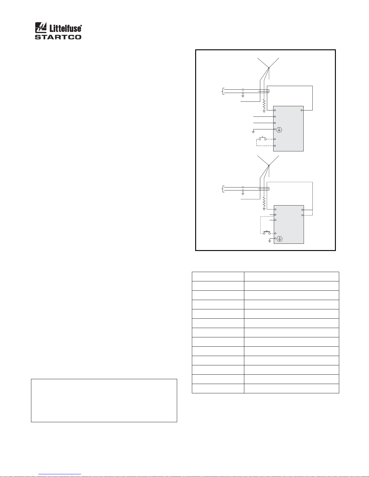
Page 34
SE-330 Neutral-Grounding-Resistor Monitor Rev. 10-D-112913
9.4 GROUND-FAULT PERFORMANCE TEST
To meet the requirements of the National Electrical
Code (NEC), as applicable, the overall ground-fault
protection system requires a performance test when first
installed. A written record of the performance test is to
be retained by those in charge of the electrical
installation in order to make it available to the authority
having jurisdiction. A test-record form is provided for
recording the date and the final results of the
performance tests. The following ground-fault system
tests are to be conducted by qualified personnel:
a) Evaluate the interconnected system in accordance
with the overall equipment manufacturer’s detailed
instructions.
b) Verify proper installation of the ground-fault current
sensor. Ensure the cables pass through the groundfault-current-sensor window. This check can be done
visually with knowledge of the circuit. The
connection of the current-sensor secondary to the SE330 is not polarity sensitive.
c) Verify that the system is correctly grounded and that
alternate ground paths do not exist that bypass the
current sensor. High-voltage testers and resistance
bridges can be used to determine the existence of
alternate ground paths.
d) Verify proper reaction of the circuit-interrupting
device in response to a simulated or controlled
ground-fault current. To simulate ground-fault
current, use CT-primary current injection (does not
apply for bushing-type CT’s). Fig. 23a shows a test
circuit using an SE-400 Ground-Fault-Relay Test
Unit. The SE-400 has a programmable output of 0.5
to 9.9 A for a duration of 0.1 to 9.9 seconds. Set the
test current to 120% of GF TRIP LEVEL.
Fig. 23b shows a test circuit using an SE-100T
Ground-Fault-Relay Tester. The SE-100T provides a
test current of 0.65 or 2.75 A for testing 0.5- and 2.0A trip levels. Inject the test current through the
current-sensor window for at least 2.5 seconds.
Verify that the circuit under test has reacted properly.
Correct any problems and re-test until the proper
reaction is verified.
e) Record the date and the results of the test on the
attached test-record form.
N
OTE: Do not inject test current directly into CT-input
terminals 8, 9, 10, and 11.
NOTE: For accurate trip-time measurement, the fault
current should not be re-applied for the time defined by the
GF TRIP TIME setting to allow the trip accumulator to
initialize.
a) USING SE-400
NEUTRAL
TO SE-330
TO SENSING
RESISTOR
TERMINAL N
b) USING SE-100T
TO SE-330
TO SENSING
TERMINAL N
RESISTOR
REMOTE
INPUT
NGR
11
OP1
NGR
L
N
REMOTE
TEST
3
L1
5
L2
1
8
RMT1
9
RMT2
NEUTRAL
C
L1
L2
RMT
SE-400
SE-100T
L
N
OP2
12
0.65 A
LO
2.75 A
HI
FIGURE 23. Ground-Fault-Test Circuits.
TABLE 3. G
D
ATE TEST RESULTS
ROUND-FAULT-TEST RECORD
Retain this record for the authority having jurisdiction.
Page 39
Page 35
SE-330 Neutral-Grounding-Resistor Monitor Rev. 10-D-112913
APPENDIX A
SE-330 REVISION HISTORY
MANUAL
RELEASE DATE
November 29, 2013 10-D-112913
October 8, 2013 10-C-100813 10A 2.08
September 12, 2013 10-B-091213 10A 2.07
August 30, 2013 10-A-083013 10 2.07
MANUAL
REVISION
HARDWARE REVISION
(REVISION NUMBER
ON PRODUCT LABEL)
11 2.12
10A
FIRMWARE REVISION
2.11
2.10
MANUAL REVISION HISTORY
R
EVISION 10-D-112913
S
ECTION 6
CE added to sensing resistors.
S
ECTION 7
Ordering information updated.
A
PPENDIX A
Updated revision history.
R
EVISION 10-C-100813
SECTION 2
Section 2.8 updated.
S
ECTION 4
Real Time Clock note added in Section 4.2.
S
ECTION 5
LED and relay status added to troubleshooting solutions.
S
ECTION 7
Ordering information updated.
A
PPENDIX A
Updated revision history.
R
EVISION 10-B-091213
PPENDIX A
A
Updated revision history.
R
EVISION 10-A-083013
ECTION 1
S
Faceplate updated.
New features added.
S
ECTION 2
Communications options updated.
Configuration switches updated.
Indication relays explanation added.
Non-volatile-memory error added.
S
ECTION 3
Connection drawing updated.
S
ECTION 4
Section heading changed to Data Interfaces.
Updated with microSD™ and USB interfaces.
Upgrade procedure added.
S
ECTION 5
Non-volatile-memory error added.
Switch S8 diagnostic LED error removed.
S
ECTION 6
Ground-fault circuit trip level updated.
USB communications specifications added.
Page 40

Page 36
SE-330 Neutral-Grounding-Resistor Monitor Rev. 10-D-112913
Resistor-fault accuracy changed.
microSD™ memory card specifications added.
ECTION 7
S
Ordering information updated.
SE-330-SMA Surface Mount Adapter is now listed as an accessory only.
A
PPENDIX A
Added revision history.
HARDWARE REVISION HISTORY
H
ARDWARE REVISION 11
Reduced ESD sensitivity of USB and SD card connectors.
H
ARDWARE REVISION 10A
Update to RTC circuit.
H
ARDWARE REVISION 10
Updated SE-330 platform to include USB and microSD™ interfaces, programmable trip level (MEM) feature, and
ability to add future options.
Real-time clock added.
Added dual cable and fiber Ethernet ports.
FIRMWARE REVISION HISTORY
F
IRMWARE REVISION 2.12
Updated DeviceNet data model for backwards compatibility with previous revision SE-330.
IRMWARE REVISION 2.11
F
Updated EtherNet/IP data model for backwards compatibility with previous revision SE-330.
IEC 61850 IED Name for SE-330 now reported correctly.
IRMWARE REVISION 2.10
F
Added support for IEC 61850 and DeviceNet protocols.
IRMWARE REVISION 2.08
F
Added support for communications options.
IRMWARE REVISION 2.07
F
Updated firmware to include USB and microSD™ interfaces, datalogging, and firmware update via microSD™.
K2 and K3 indication relays can be configured for fail-safe or non-fail-safe operation.
Trip records increased to 100 with date and time stamping.
 Loading...