

Datasheet SD600N25PSC, SD600N25PTC, SD600N28MC, SD600N28MSC, SD600N28MTC Datasheet (International Rectifier)
...Page 1
Typical Applications
Converters
Power supplies
Machine tool controls
High power drives
Medium traction applications
Parameters Units
SD600N/R
04 to 20 25 to 32
I
F(AV)
600 600 A
@ T
C
92 54 °C
I
F(RMS)
940 940 A
I
FSM
@ 50Hz 13000 10500 A
@ 60Hz 13600 11000 A
I2t@
50Hz 845 551 K A2s
@ 60Hz 772 503 K A2s
V
RRM
range 400 t o 2000 2500 to 3200 V
T
J
- 40 to 180 - 40 to 150 °C
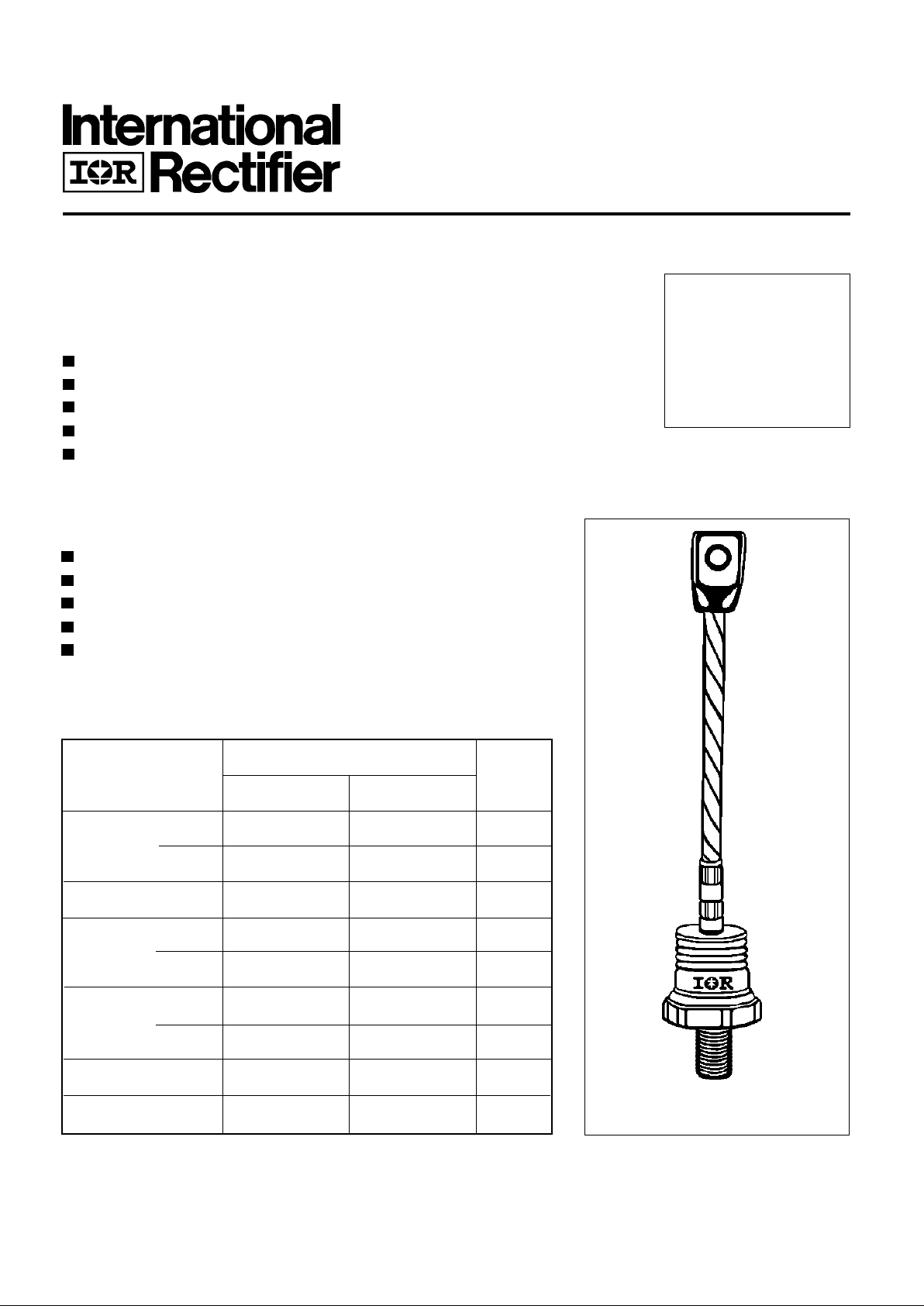
Major Ratings and Characteristics
case style
B-8
SD600N/R SERIES
STANDARD RECOVERY DIODES
600A
Stud V ersion
Bulletin I2070/B
Features
Wide current range
High voltage ratings up to 3200V
High surge current capabilities
Stud cathode and stud anode version
Standard JEDEC types
Page 2
SD600N/R Series
SD600N/R 35
Voltage V
RRM
, maximum repetitive V
RSM
, maximum non- I
RRM
max.
Type number Cod e peak reverse voltage repetitive peak rev. voltage @ T
J
= TJ max.
VVmA
04 400 500
08 800 900
12 1200 1300
16 1600 1700
20 2000 2100
25 2500 2600
28 2800 2900
32 3200 3300
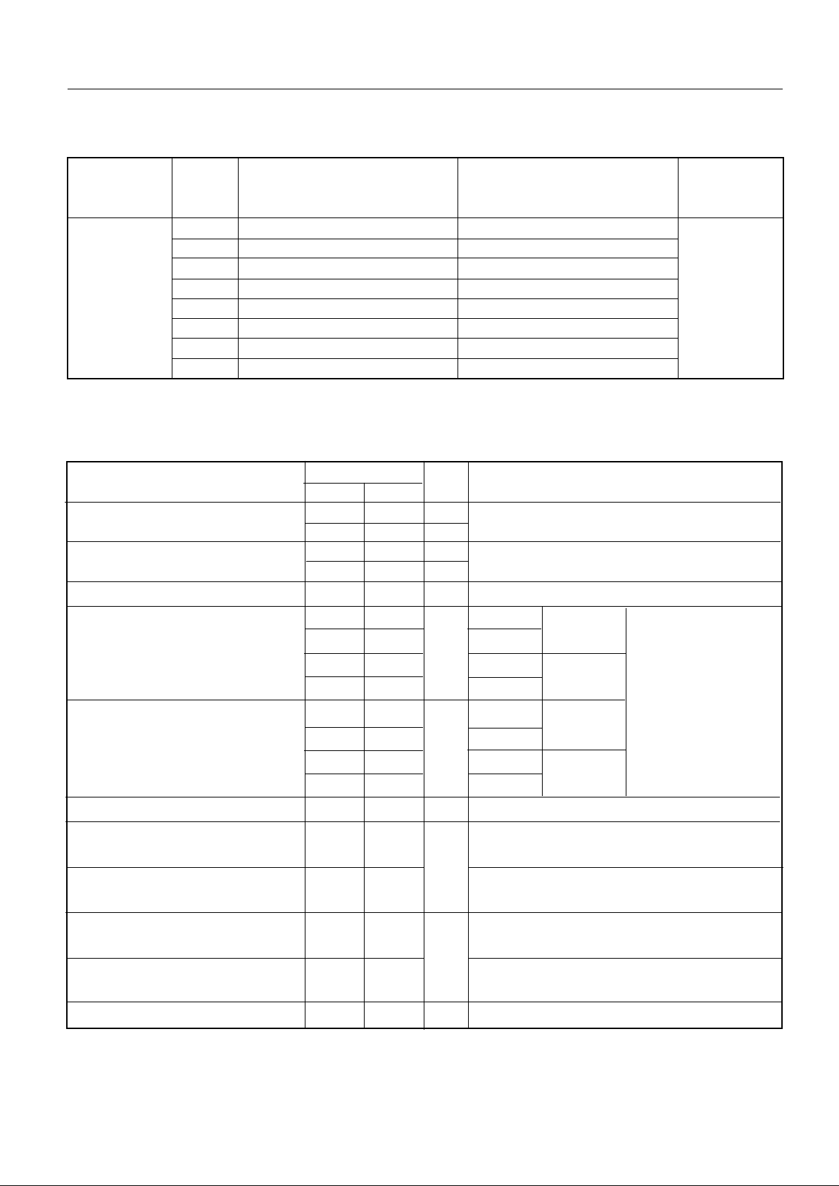
ELECTRICAL SPECIFICATIONS
Voltage Ratings
I
F(AV)
Max. average forward current 600 600 A 180° conduction, half sine wave
@ Case temperature 92 54 °C
I
F(AV)
Max. average forward current 570 375 A 180° conduction, half sine wave
@ Case temperature 100 100 °C
I
F(RMS)
Max. RMS forward current 940 940 A DC @ TC = 75°C (04 to 20), TC = 36°C (25 to 32)
I
FSM
Max. peak, one-cycle forward, 13000 10500 t = 10ms No voltage
non-repetitive surge current 13600 11000 t = 8.3ms reapplied
10900 8830 t = 10ms 100% V
RRM
11450 9250 t = 8.3ms reapplied Sinusoidal half wave,
I
2
t Maximum I2t for fusing 845 551 t = 10ms No voltage Initial TJ = TJ max.
772 503 t = 8.3ms reapplied
598 390 t = 10ms 100% V
RRM
546 356 t = 8.3ms reapplied
I
2
√t Maximum I2√t for fusing 8450 5510 KA2√s t = 0.1 to 10ms, no voltage reapplied
V
F(TO)1
Low level value of threshold
voltage
V
F(TO)2
High level value of threshold
voltage
r
f1
Low level value of forward
slope resistance
r
f2
High level value of forward
slope resistance
V
FM
Max. forward voltage drop 1.31 1.44 V Ipk= 1500A, TJ = TJ max, tp = 10ms sinusoidal wave
SD600N/R
04 to 20 25 to 32
Parameter Units Conditions
0.31 0.38 (I > π x I
F(AV)
),TJ = TJ max.
0.35 0.40 (16.7% x π x I
F(AV)
< I < π x I
F(AV)
), TJ = TJ max.
mΩ
0.87 0.88 (I > π x I
F(AV)
),TJ = TJ max.
0.78 0.84 (16.7% x π x I
F(AV)
< I < π x I
F(AV)
), TJ = TJ max.
V
KA2s
A
Forward Conduction
Page 3
SD600N/R Series
Parameter U n i ts Conditions
SD600N/R
04 to 20 25 to 32
T
J
Max. junction operating temperature range -40 to 180 -40 to 150
T
stg
Max. storage temperature range -55 to 200 -55 to 200
R
thJC
Max. thermal resistance, junction to case 0.1 DC operation
R
thCS
Max. thermal resistance, case Mounting surface, smooth, flat and
to heatsink greased
T Max. allowed mounting torque ±10% 50 Nm Not lubricated threads
wt Approximate weight 454 g
Case style B - 8 See Outline Table
°C
0.04
K/W
Thermal and Mechanical Specifications
180° 0.012 0.008 TJ = TJ max.
120° 0.014 0.014
90° 0.017 0.019
60° 0.025 0.026
30° 0.042 0.042
Conduction angle Sinusoidal conduction Rectangular conduction Units Conditions
K/W
∆R
thJC
Conduction
(The following table shows the increment of thermal resistence R
thJC
when devices operate at different conduction angles than DC)
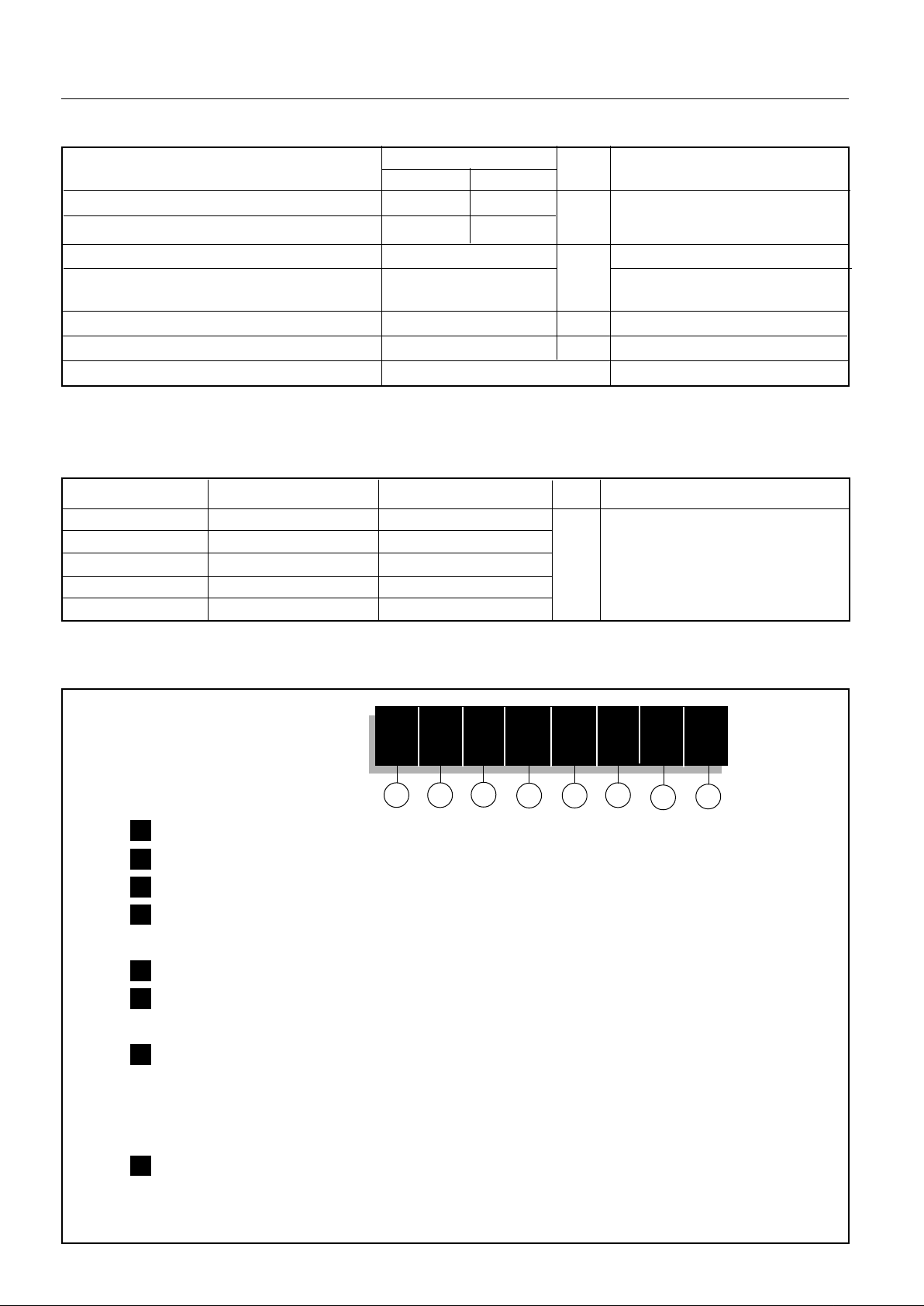
Ordering Information Table
1 2
3
4 5
6
Device Code
SD 60 0 N 32 P S C
8
7
1 - Diode
2 - Essential part number
3 - 0 = Standard recovery
4 - N = Stud Normal Polarity (Cathode to Stud)
R = Stud Reverse Polarity (Anode to Stud)
5 - Voltage code: Code x 100 = V
RRM
(See Voltage Ratings table)
6 - P = Stud base B-8 3/4" 16UNF-2A
M = Stud base B-8 M24 X 1.5
7 - S = Isolated lead with silicone sleeve
(Red = Reverse Polarity; Blue = Normal Polarity)
T = Threaded Top Terminal 3/8" 24UNF-2A
None = Non isolated lead
8 - C = Ceramic Housing
NOTE: Available for rotating applications (Contact factory)
Page 4

SD600N/R Series
Outlines Table
Case Style B-8
All dimensions in millimeters (inches)
Case Style B-8 with top thread terminal 3/8"
All dimensions in millimeters (inches)
26 (1.023) MAX.
10.5 (0.41) DIA.
12 (0.47) MIN.
38 (1.5)
DIA. MAX.
CERAMIC HOUSING
SW 45
C.S. 70mm
5(0.20) ± 0.3(0.01)
2
3/4"-16UNF-2A *
* FOR METRIC DEVICE: M24 x 1.5 - SCREW LENGTH — 21(0.83) MAX.
38 (1.5)
DIA. MAX.
CERAMIC HOUSING
SW 45
3/4"-16UNF-2A *
3/8"-24UNF-2A
17 (0.67) DIA.
* FOR METRIC DEVICE: M24 x 1.5 - SCREW LENGTH — 21(0.83)
M
Page 5

SD600N/R Series
20 40 60 80 100 120 140 160 180
M aximum All owable Ambien t Temper ature ( °C)
1
K
/
W
R
=
0
.
0
2
K
/
W
-
D
e
l
t
a
R
t
h
S
A
0
.
0
4
K
/
W
0
.
0
8
K
/
W
0
.
1
K
/
W
0
.
2
K
/
W
0
.
4
K
/
W
0
.
6
K
/
W
1
.
8
K
/
W
0
1
0
0
2
0
0
3
0
0
4
0
0
5
0
0
6
0
0
7
0
0
8
0
0
0
1
0
0
2
0
0
3
0
0
4
0
0
5
0
0
6
0
0
180°
120°
90°
60°
30°
RMS Lim it
Conduction Angle
M
a
x
i
m
u
m
A
v
e
r
a
g
e
F
o
r
w
a
r
d
P
o
w
e
r
L
o
s
s
(
W
)
Average For w ard Curren t (A )
SD600N/R Series
(400V to 2000V)
T = 180°C
J
Fig. 5 - Forward Power Loss Characteristics
50
60
70
80
90
100
110
120
130
140
150
0 100 200 300 400 500 600 700
30°
60°
90°
120°
180°
A v er age Fo r w ar d Cu r rent (A )
Conduction Angle
M aximum All owable Case Temperature ( °C)
SD600N/R Series (2500V to 3200V)
R (DC) = 0.1 K/W
thJC
30
40
50
60
70
80
90
100
110
120
130
140
150
0 200 400 600 800 1000
30°
60°
90°
180°
DC
120°
Aver age For ward Curr ent (A)
Conduction P er i od
Max imum Allowable Case Tempe r at ure ( ° C)
SD600N/R Series (250 0V to 3200 V)
R (DC) = 0.1 K /W
thJC
Fig. 3 - Current Ratings Characteristics
Fig. 4 - Current Ratings Characteristics
Fig. 1 - Current Ratings Characteristics Fig. 2 - Current Ratings Characteristics
70
80
90
100
110
120
130
140
150
160
170
180
0 200 400 600 800 1000
30°
60°
90°
180°
DC
120°
Average Forw ard Curren t (A )
Conduction P er iod
M aximum Allo wable C ase Te m peratu re (°C )
R (DC) = 0.1 K/ W
thJC
SD600N /R Series (400V to 2000V)
80
90
100
110
120
130
140
150
160
170
180
0 100 200 300 400 500 600 700
30°
60°
90°
120°
180°
Ave rage Forw ard Cu rre nt (A)
Conduction Angle
M aximum Allow able Case Temperature ( °C )
R (DC) = 0.1 K /W
thJC
SD600N /R Series (400V to 2000V)
Page 6

SD600N/R Series
25 50 75 100 125 150
Maximum All owable Ambient T emperature (°C)
1
K
/
W
R
=
0
.
0
2
K
/
W
-
D
e
l
t
a
R
t
h
S
A
0
.
0
4
K
/
W
0
.
0
6
K
/
W
0
.
1
K
/
W
0
.
2
K
/
W
0
.
4
K
/
W
0
100
200
300
400
500
600
700
800
900
0 1 0 0 20 0 3 0 0 40 0 500 600
180°
120°
90°
60°
30°
RMS Limit
Conduction An gle
M
a
x
i
m
u
m
A
v
e
r
a
g
e
F
o
r
w
a
r
d
P
o
w
e
r
L
o
s
s
(
W
)
Average Forwar d Cu rrent (A)
SD600N/R Series
(2500V to 3200V)
T = 150°C
J
25 50 75 100 125 150
Maximum Allo w able Ambien t Temperatur e ( ° C )
1
K
/
W
R
=
0
.
0
2
K
/
W
-
D
e
l
t
a
R
t
h
S
A
0
.
0 4
K
/
W
0
.
0
6
K
/W
0
.
1
K
/
W
0
.
2
K
/
W
0
.
4
K
/
W
0
100
200
300
400
500
600
700
800
900
1000
1100
0 100 200 30 0 400 500 600 700 800 900
DC
180°
120°
90°
60°
30°
RMS Lim i t
Conduction Peri od
M
a
x
i
m
u
m
A
v
e
r
a
g
e
F
o
r
w
a
r
d
P
o
w
e
r
L
o
s
s
(
W
)
Average Forward Curr ent ( A)
SD600N/R Series
(2500V to 3200V)
T = 150°C
J
Fig. 7 - Forward Power Loss Characteristics
Fig. 8 - Forward Power Loss Characteristics
20 40 60 80 100 120 140 160 180
M ax i m um Al low abl e A mbi e nt Temper atu r e (° C )
1
K
/
W
R
=
0
.
0
2
K
/
W
-
D
e
l
t
a
R
t
h
S
A
0
.
0
4
K
/
W
0
.
0
8
K
/
W
0
.
1
K
/
W
0
.
2
K
/
W
0
.
4
K
/
W
0
.
6
K
/
W
1
.
8
K
/
W
0
1
0
0
2
0
0
3
0
0
4
0
0
5
0
0
6
0
0
7
0
0
8
0
0
9
0
0
1
0
0
0
1
1
0
0
0
2
0
0
4
0
0
6
0
0
8
0
0
1
0
0
0
DC
180°
120°
90°
60°
30°
RMS Lim it
Conduction Period
M
a
x
i
m
u
m
A
v
e
r
a
g
e
F
o
r
w
a
r
d
P
o
w
e
r
L
o
s
s
(
W
)
Average Forw ard Curren t ( A)
SD600N /R Series
(400V to 2000V)
T = 180 °C
J
Fig. 6 - Forward Power Loss Characteristics
Page 7

SD600N/R Series
2000
4000
6000
8000
10000
110100
Number Of Equal Amplitude Half Cycle Current Pulses (N)
Peak Half Sin e W av e Forw ar d Curren t (A )
Initial T = 150°C
@ 60 Hz 0.0083 s
@ 50 H z 0.0 100 s
J
SD600N /R Series
(2500V to 3200V)
At Any Rated Load Conditio n And With
Rated V A pplied Foll ow ing Surge.
RRM
2000
4000
6000
8000
10000
12000
0.01 0.1 1
Pulse Train Dur ati on (s)
Pea k Ha lf Sine Wave Forward Cur r ent (A)
Initial T = 150 °C
No Voltage Reapplied
Rated V Reapplied
J
RRM
Versus Pu lse Tr ain Duration.
SD600N/R Series
(2500V to 3200V)
M aximum Non Repetitive Su rge Cur rent
100
1000
10000
01234
T = 25°C
J
Instan tane ous Forw ard Voltage (V)
Instantaneous F orward Current (A)
T = 180°C
J
SD600N/ R Se r i e s
(400V to 2000V)
100
1000
1000 0
012345
T = 2 5 ° C
J
I n stantaneo u s For war d Voltage (V )
Instantaneous Forward Cur re nt (A)
T = 150 °C
J
SD600N/ R Se rie s
(2500V to 3200V)
Fig. 13 - Forward Voltage Drop Characteristics
Fig. 14 - Forward Voltage Drop Characteristics
Fig. 11 - Maximum Non-Repetitive Surge Current
Fig. 12 - Maximum Non-Repetitive Surge Current
2000
4000
6000
8000
10000
12000
110100
N umber Of Equal Amplitude Half Cycle Curr ent Pul s es (N)
Peak Hal f Sin e Wave For w ard Current ( A)
At Any Rated Load Condition And Wi th
Rated V A pplied Fol lo wing Surge.
RRM
Initial T = 180°C
@ 60 H z 0. 0083 s
@ 50 H z 0. 0100 s
J
SD6 00N/ R Se ri e s
(400V to 2000V)
2000
4000
6000
8000
10000
12000
14000
0.01 0.1 1
Pulse Train D ur ation (s)
Peak Ha lf S ine Wave Forward Current (A)
Maxi mum Non Repetitive Sur ge Current
Ver sus Pulse Train Dur at ion.
Ini tial T = 180 °C
No Voltage Reapplied
Rated V Reappl ied
RRM
J
SD600N /R Series
(400V to 2000V)
Fig. 9 - Maximum Non-Repetitive Surge Current Fig. 10 - Maximum Non-Repetitive Surge Current
Page 8

SD600N/R Series
Fig. 15 - Thermal Impedance Z
thJC
Characteristics
0.001
0.01
0.1
1
0.001 0.01 0.1 1 10
S quare Wave Pulse Duration (s)
thJC
Transient Therm al Impedance Z (K/W)
Steady S tate Value:
R = 0.1 K/W
(D C Operation)
thJC
SD600N/R Series
 Loading...