

Datasheet SD250OC12K, SD250OC16K, SD250OC20K, SD250OC25K Datasheet (International Rectifier)
Page 1

DISCRETE POWER DIODES and THYRISTORS
DATA BOOK
Page 2
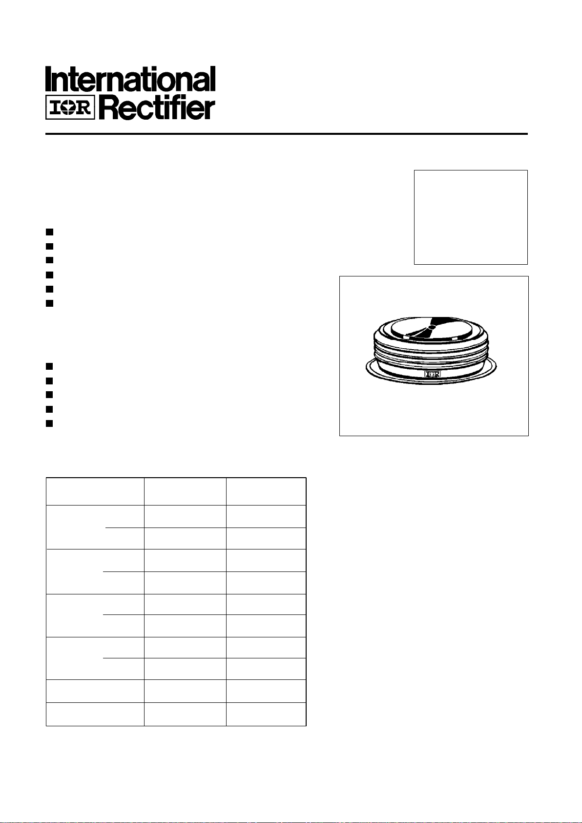
SD2500C..K SERIES
STANDARD RECOVERY DIODES
Hockey Puk Version
3000A
Bulletin I2089/A
Features
Wide current range
High voltage ratings up to 2500V
High surge current capabilities
Diffused junction
Hockey Puk version
Case style DO-200AC (K-PUK)
Typical Applications
Converters
Power supplies
Machine tool controls
High power drives
Medium traction applications
Major Ratings and Characteristics
I
F(AV)
3000 A
@ T
hs
55 °C
I
F(RMS)
5000 A
@ T
hs
25 °C
I
FSM
@ 50Hz 31000 A
@ 60Hz 32460 A
I
2
t @ 50Hz 4810 KA2s
@ 60Hz 4390 KA
2
s
V
RRM
range 1200 to 2500 V
T
J
- 40 to 180 °C
Parameters SD2500C..K Units
case style DO-200AC (K-PUK)
Page 3
SD2500C..K Series
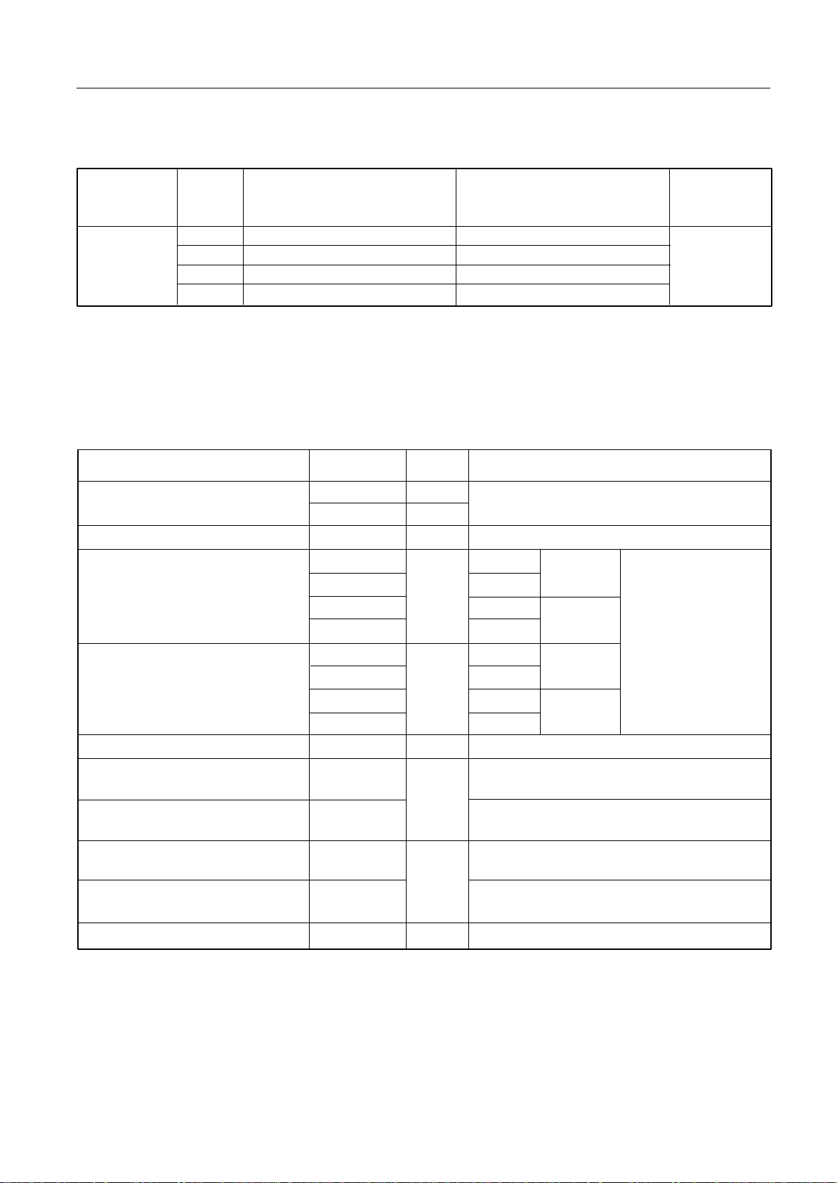
Voltage V
RRM
, maximum repetitive V
RSM
, maximum non- I
RRM
max.
Type number Code peak reverse voltage repetitive peak rev. voltage
@ TJ = 180°C
V V mA
12 1200 1300
16 1600 1700
20 2000 2100
25 2500 2600
ELECTRICAL SPECIFICATIONS
Voltage Ratings
I
F(AV)
Max. average forward current 3000 (1550) A 180° conduction, half sine wave
@ Heatsink temperature 55 (85) °C Double side (single side) cooled
I
F(RMS)
Max. RMS forward current 5000 A @ 25°C heatsink temperature double side cooled
I
FSM
Max. peak, one-cycle forward, 31000 t = 10ms No voltage
non-repetitive surge current 32460 t = 8.3ms reapplied
26050 t = 10ms 100% V
RRM
27300 t = 8.3ms reapplied Sinusoidal halfwave,
I
2
t Maximum I2t for fusing 4810 t = 10ms No voltage Initial TJ = TJ max.
4390 t = 8.3ms reapplied
3400 t = 10ms 100% V
RRM
3100 t = 8.3ms reapplied
I
2
√t Maximum I2√t for fusing 48100 KA2√s t = 0.1 to 10ms, no voltage reapplied
V
F(TO)1
Low level value of threshold
voltage
V
F(TO)2
High level value of threshold
voltage
r
f
1
Low level value of forward
slope resistance
r
f
2
High level value of forward
slope resistance
V
FM
Max. forward voltage drop 1.41 V Ipk= 4000A, TJ = TJ max, tp = 10ms sinusoidal wave
A
KA2s
0.76 (16.7% x π x I
F(AV)
< I < π x I
F(AV)
), TJ = TJ max.
Parameter SD2500C..K Units Conditions
Forward Conduction
V
mΩ
0.16 (16.7% x π x I
F(AV)
< I < π x I
F(AV)
), TJ = TJ max.
0.97 (I > π x I
F(AV)
),TJ = TJ max.
0.13 (I > π x I
F(AV)
),TJ = TJ max.
SD2500C..K 75
Page 4

SD2500C..K Series
Fig. 3 - Current Ratings Characteristics Fig. 4 - Current Ratings Characteristics
Fig. 5 - Forward Power Loss Characteristics Fig. 6 - Forward Power Loss Characteristics
Fig. 7 - Maximum Non-Repetitive Surge Current Fig. 8 - Maximum Non-Repetitive Surge Current
Page 5

SD2500C..K Series
Fig. 9 - Forward Voltage Drop Characteristics
Fig. 10 - Thermal Impedance Z
thJC
Characteristics
Page 6

SD2500C..K Series
∆R
thJ-hs
Conduction
(The following table shows the increment of thermal resistence R
thJ-hs
when devices operate at different conduction angles than DC)
Ordering Information Table
1 - Diode
2 - Essential part number
3 - 0 = Standard recovery
4 - C = Ceramic Puk
5 - Voltage code: code x 100 = V
RRM
(see Voltage Ratings Table)
6 - K = Puk Case DO-200AC (K-PUK)
1 2
3
4 5 6
Device Code
SD 250 0 C 25 K
T
J
Max. junction operating temperature range -40 to 180
T
stg
Max. storage temperature range -55 to 200
R
thJ-hs
Max. thermal resistance, junction 0.042 DC operation single side cooled
to heatsink 0.020 DC operation double side cooled
F Mounting force, ± 10% 22250 N
(2250) (Kg)
wt Approximate weight 425 g
Case style DO-200AC(K-PUK) See Outline Table
Parameter SD2500C..K Units Conditions
Thermal and Mechanical Specifications
°C
K/W
Sinusoidal conduction Rectangular conduction
Conduction angle Units Conditions
Single Side Double Side Single Side Double Side
180° 0.002 0.002 0.001 0.001
120° 0.002 0.002 0.002 0.002
90° 0.003 0.003 0.003 0.003 K/W T
J
= TJ max.
60° 0.004 0.004 0.004 0.004
30° 0.007 0.007 0.007 0.007
Page 7

SD2500C..K Series
Outline Table
Case Style DO-200AC (K-PUK)
All dimensions in millimeters (inches)
Fig. 1 - Current Ratings Characteristics Fig. 2 - Current Ratings Characteristics
3.5(0.14) DIA. NOM. x
2.5(0.1) DEEP MIN. BOTH ENDS
74.5 (2.93) DIA . MAX.
1 (0.04) MIN.
BOTH ENDS
TWO PLACES
47.5 (1.87) DIA. MAX.
67 (2.64) DIA. MAX.
2 7 .5 (1.08) MAX.
 Loading...