

Page 1
RF & MICROWAVE TRANSISTORS
.470 - 860 MHz
.28 VOLTS
.CLASS AB PUSH PULL
. D ESI GN ED FOR H I GH POWER
CAPABILITY
. GOLD METALLIZATION
.DIFFUSED EMITTER BALLAST
RESISTORS
. CO MMON EMITTER CONFIGURATION
.INTERNAL I NPUT MATCHING
.P
OUT
150 W MIN. WITH 6.5 dB GAIN
=
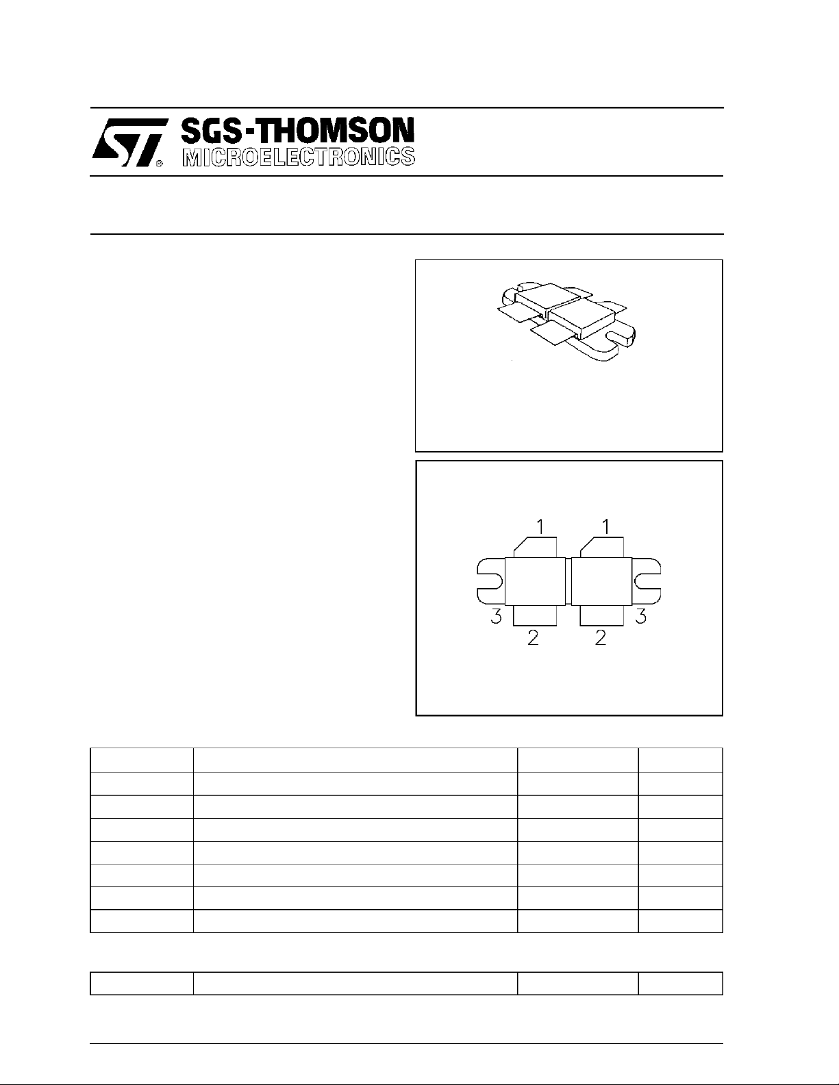
SD1492
TV/LINEAR APPLICATIONS
2 x .437 x .450 2LFL (M175)
epoxy sealed
ORDER CODE
SD1492
PIN CONNECTION
BRANDING
SD1492
DESC RIPTION
The SD1492 is a gold metallized epitaxial silicon
NPN planar transistor using diffused emitter ballast
resistors for high linearity Class AB operation in
UHF and Band IV, V television transmitters and
transposers.
ABSOLUTE MAXIMUM RATINGS (T
Symbol Parameter Value Uni t
V
CBO
V
CEO
V
EBO
I
C
P
DISS
T
J
T
STG
THERMA L DA TA
R
TH(j-c)
Collector-Base Voltage 60 V
Collector-Emitter Voltage 30 V
Emitter-Base Voltage 3.0 V
Device Current 25 A
Power Dissipation 318 W
Junction Temperature +200
Storage Temperature
Junction-Case Thermal Resistance 0.55 °C/W
case
= 25°C)
1. Collector 3. Emitter
2. Base
65 to +150
−
°
C
°
C
November 1992
1/7
Page 2
SD1492
ELECTRICAL SPECIFICATIONS (T
case
= 25°C)
STATIC
Symbol Test Conditions
BV
CBOIC
BV
CEOIC
BV
EBOIE
I
CES
h
FE
= 100mA IE= 0mA 60 — — V
= 100mA IB= 0mA 30 — — V
= 50mA IC= 0mA 3.0 — — V
VCE= 28V IE= 0mA — — 10 mA
VCE= 5V IC= 3A 15 — 70 —
DYNAMIC
Symbol Test C ond itions
P
*f=860 MHz VCE= 28 V ICQ= 2 x 500 mA 150 — — W
OUT
PG*P
η
c* P
C
OB
Note: * 1 dB Compr ess ion Point
= 150 W VCE= 28 V ICQ= 2x500mA 6.5 — — dB
OUT
= 150 W VCE= 28 V ICQ= 2x500mA 45 — — %
OUT
f = 1 MHz VCB= 28 V — — 100 pF
Value
Min. Typ. Max.
Value
Min. Typ. Max.
Unit
Unit
2/7
Page 3
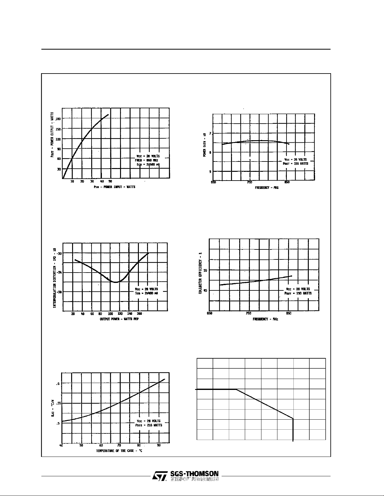
TYPICA L PERFO R MA NCE
SD1492
POWER OUTPUT vs POWER INPUT
INTERMODULATION DISTORTION vs POWER
OUTPUT
BROADBAND POWER GAIN vs FREQUENCY
COLLECTOR EFFICIENCY vs FREQUENCY
THERMAL RESISTANCE vs CASE TEMPERATURE
SAFE OPERATING AREA
40
35
30
25
20
15
10
5
0
0 5 10 15 20 25 30 35 40
3/7
Page 4

SD1492
IMPEDA NCE DATA
650 MHz
700 MHz
FREQ. ZIN(Ω)ZCL(Ω)
900 MHz 2.65 + j 0.8 2.4 − j1.6
860 MHz 3.2 + j 1.6 2.3 − j0.9
700 MHz 2.0 + j 2.4 1.5 − j0.8
650 MHz 1.0 + j 1.3 —
550 MHz 0.6 + j 0.4 —
470 MHz 0.3 − j 1.2 1.2 − j1.3
Z
IN
860 MHz
550 MHz
470 MHz
700 MHz
470 MHz
900 MHz
860 MHz
900 MHz
Z
CL
4/7
Page 5

PHOTO MA STER OF TEST CIRCU I T
SD1492
TEST CIRCUIT
B1, B2 : Coaxial Cable 25, 43mm
C1, C2
C6, C7 : 330pF, ATC 100B
C3 : .8 - 8pF Johanson Gigatrim
C4 : 4.7pF + 3.9pF, ATC 100B
C5 : 3.9pF + 1.7pF, ATC 100B + .8 - 8pF Johanson
C8 : 120pF, ATC 100B
C9 : 1.5nF, ATC 100B
C10 : 10nF + 47µF, 63V
C11 : 1.5nF, ATC 100B + 10nF
C12 : 470pF + 1.5nF, ATC 100B + 100µF, 63V
Substrate: Teflon Glass Er=2.55, 30Mils
Gigatrim
L1, L18 : Printed Line 50
L2, L17 : Printed Line 26.7Ω, 10mm
L3, L16 : Printed Line 60Ω, 10.5mm
L4, L15 : Printed Line 50Ω, 43mm
L5 : Printed Line 25Ω, 13.5mm
L6 : Printed Line 21Ω, 15mm
L7 : Printed Line 10.5Ω, 12.5mm
L8 : Printed Line 8Ω, 7.5mm
L9, l10 : Printed Line 50Ω, 10mm
L11 : Printed Line9.5Ω, 10.5mm
L12 : Printed Line 11Ω, 14.5mm
L13 : Printed Line 15.5Ω, 8.5mm
L14 : Printed Line 19Ω, 3.5mm
L19 : 2 Turns, #16 AWG
L20 : 8 Turns, #16 AWG
L21, L22 : 12 Turns, #22 AWG
Ω
5/7
Page 6

SD1492
BIA S VOLTAG E SOU RCE
C15 : 10nF + 100nF + 10µF
C16 : 10nF
C17 : 1µF
C18 : 1.2nF + 27nF + 10µF
D1 : AAY 49 Ge Diode Thermally Connected with Q3 heatsink
D2 : 1N 400S - Si Diode Thermally Connected with Q3 heatsink
D3 : 1n 400S - Si Diode Thenmally Connected with SD1492 (RF Transistors) Flange
L6, L9 : Ferrite Choice
Q : Box 63B
R6 : 100ΩTrimpot
R7 : 470Ω, 1/2W
6/7
Page 7

PACKAGE MECHANICAL DATA
Ref.: Dwg. No.12-0175 rev. A
SD1492
Information furnished is believed to be accurate and reliable. However, SGS-THOMSON Microelectronics assumes no responsibility
for the consequences of use of such information nor for any infringement of patents or other rights of third parties which may result
from its use. No license is granted by implication or otherwise under any patent or patent rights of SGS-THOMSON Microelectronics. Specifications mentioned in this publication are subject to change without notice. This publication supersedes and replaces all
information previously supplied. SGS-THOMSON Microelectronics products are not authorized for use as critical components in life
support devices or systems without express written approval of SGS-THOMSON Microelectronics.
1994 SGS-THOMSON Microelectronics - All Rights Reserved
Australia - Brazil - France - Germany - Hong Kong - Italy - Japan - Korea - Malaysia - Malta - Morocco - The Netherlands -
Singapore - Spain - Sweden - Switzerland - Taiwan - Thailand - United Kingdom - U.S.A.
SGS-THOMSON Microelectronics GROUP OF COMPANIES
7/7
 Loading...