

Page 1

.30 MHz
.12.5 VOLTS
.IMD −30 dB
. COMMON EMITTER
.GOLD METALLIZATION
.P
OUT
100WMIN.WITH12.0dBGAIN
=
SD1487
RF & MICROWAVE TRANSISTORS
HF SSB APPLICA TIONS
.500 4LF L (M174)
epoxy sealed
ORDER CODE
SD1487
PIN CONNECTION
BRANDING
SD1487
DESCRIPTI ON
The SD1487 is a 12.5 V Class C epitaxial silicon
NPN planar transistor designed primarily for HF
communications. This device utilizes state-of-theart diffused emitter ballasting to achieve extreme
ruggedness under severe operating conditions.
ABSOLUTE MAXIMUM RATINGS (T
Symbol Parameter Value Uni t
V
CBO
V
CEO
V
EBO
I
C
P
DISS
T
J
T
STG
THERMA L DA TA
R
TH(j-c)
Collector-Base Voltage 36 V
Collector-Emitter Voltage 18 V
Emitter-Base Voltage 4.0 V
Device Current 20 A
Power Dissipation 290 W
Junction Temperature +200
Storage Temperature
Junction-Case Thermal Resistance 0.6 °C/W
case
= 25°C)
1. Collector 3. Base
2. Emitter 4. Emitter
65 to +150
−
°
C
°
C
November 1992
1/5
Page 2
SD1487
ELECTRICAL SPECIFICA TIONS (T
case
= 25°C)
STATIC
Symbol Test Conditions
BV
BV
BV
BV
I
CES
h
CBO
CES
CEO
EBO
FE
IC= 100mA IE= 0mA 36 — — V
IC= 100mA VBE= 0V 36 — — V
IC= 100mA IB= 0mA 18 — — V
IE= 20mA IC= 0mA 4.0 — — V
VCE= 15V IE= 0mA — — 20 mA
VCE= 5V IC= 5A 10 — 200 —
DYNAMIC
Symbol Test C ond itions
P
OUT
G
P
IMD3*P
C
OB
*N ote: f= 30 + 30.00 1M H z
f = 30 MHz VCE= 12.5 V ICQ= 150mA 100 — — W
f = 30 MHz VCE= 12.5 V ICQ= 150mA 11 13 — dB
= 100WPEP VCE= 12.5 V ICQ= 150mA — — −30 dBc
OUT
f = 1 MHz VCB= 12.5 V — 400 — pF
Value
Min. Typ. Max.
Value
Min. Typ. Max.
Unit
Unit
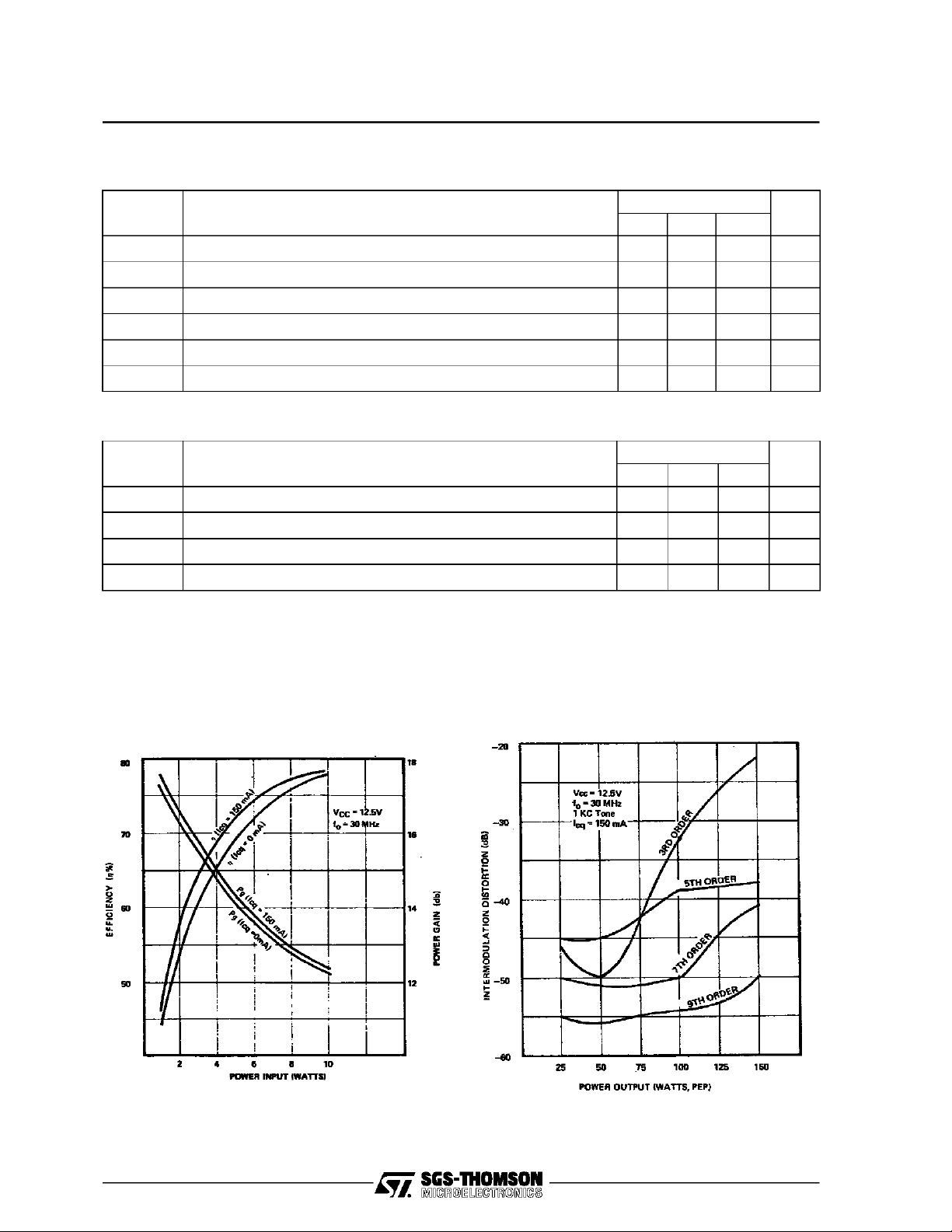
TYPICA L PERFO R MA NCE
POWER GAIN & COLLECTOR
EFFICI EN CY vs POWER INPUT
IMD vs POWER OUTPUT, PEP
2/5
Page 3

TYPICAL PERFO RM AN CE (cont ’d )
POWER OU T PUT vs POWER INPUT
SD1487
IMPEDA NCE DATA
FREQ. ZIN(Ω)ZCL(Ω)
30 MHz 0.57 + j 0.78 0.80 + j 0.43
P
= 100 W PEP
OUT
VCE= 12.5 V
3/5
Page 4

SD1487
TEST CIRCUIT
4/5
C1 : 9 - 180pF Arco 463
C2 : 5 - 380pF Arco 465
C3 : 200pF Arco 465
C4, C6 : 170pF Arco 469
C7 : 0.1µF Ceramic Disc
C5, C8 : 1000pF Unelco
C9 : 10µF Electrolytic, 35Vdc
C10 : 1000µF Electrolytic, 35Vdc
L1 : 2 1/2 Turns,#14 AWG, I.D. Loose Wound
L2 : 16 Turns, #16 AWG, Enameled Wire on
Micrometals Torroid #T-94
L3 : Copper Strap 1/4” Widht, Length 1 1/2,
L4 : 4 Turns, #16 AWG, Enameled Wire 3/8” I.D.
L5 : 5 Turns, #18 AWG on 1/4” I.D. Coil Form
R1, R2,
R3 : 1.5 Ohm, 1 Watt Carbon
Height 1/2”
Length 1/2”, Ferrite Slug
Page 5

PACKAGE MECHANICAL DATA
Ref.: Dwg. No.12-0174
SD1487
Information furnished is believed to be accurate and reliable.However, SGS-THOMSON Microelectronicsassumes no responsability forthe
consequences of useof suchinformationnor for any infringementofpatents or other rights of third parties which mayresultsfromitsuse. No
license isgranted by implicationor otherwise underany patent orpatentrights ofSGS-THOMSON Microelectronics. Specificationsmentioned
in this publication aresubjectto changewithout notice.Thispublication supersedes and replaces allinformationpreviously supplied.
SGS-THOMSON Microelectronicsproducts arenotauthorized foruse ascritical componentsin lifesupport devicesorsystems withoutexpress
written approvalofSGS-THOMSONMicroelectonics.
1994 SGS-THOMSON Microelectronics- All RightsReserved
Australia - Brazil - France- Germany- HongKong - Italy-Japan - Korea - Malaysia - Malta - Morocco - The Netherlands -
Singapore - Spain - Sweden- Switzerland -Taiwan - Thailand - United Kingdom - U.S.A
SGS-THOMSON MicroelectronicsGROUP OF COMPANIES
5/5
 Loading...