

Page 1
Description
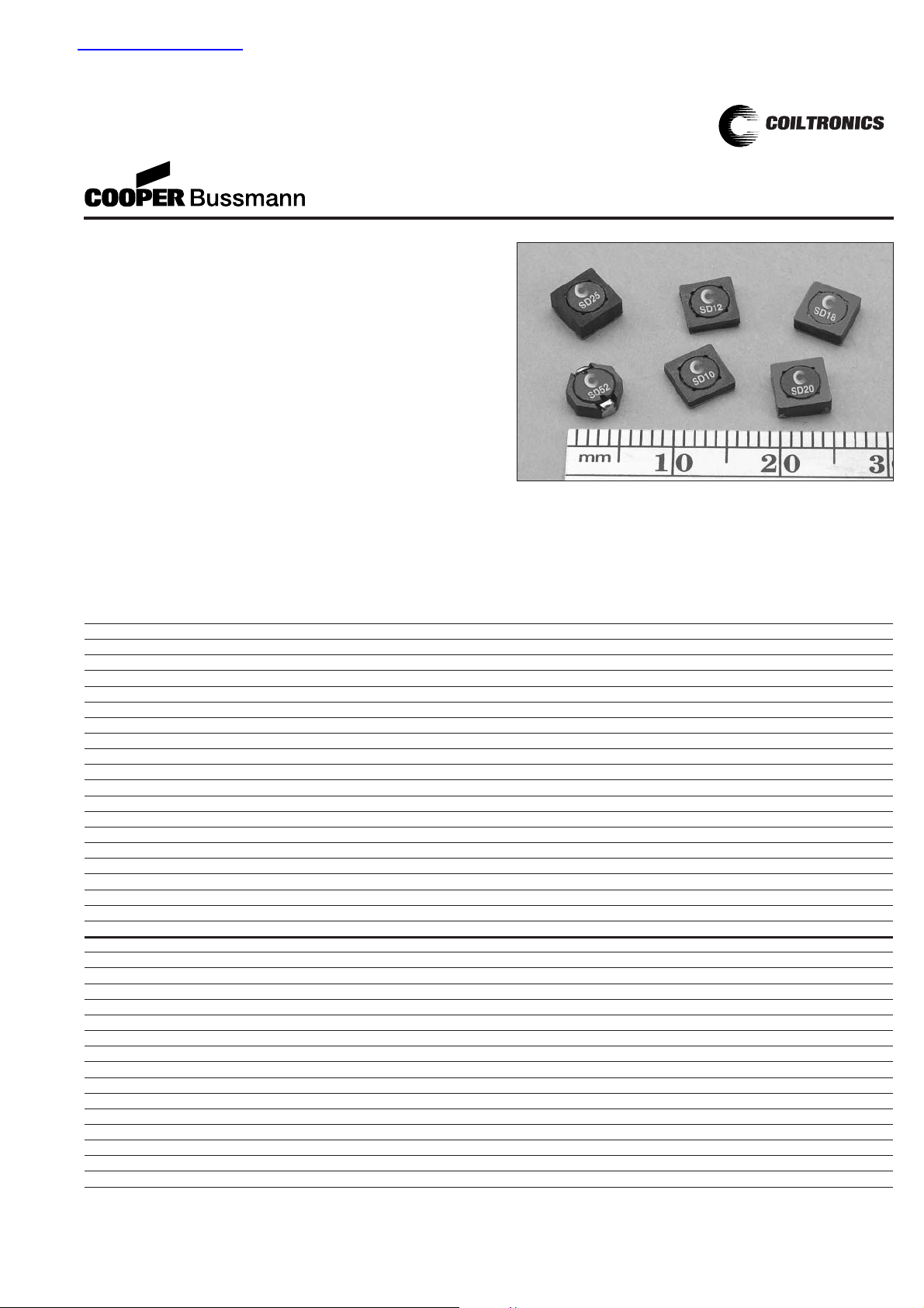
• Six sizes of shielded drum core inductors with low
profiles (as low as 1.0mm) and high power density
• Inductance range from .47uH to 1000uH
• Current range from 6.00 to 0.088 Amps
• Ferrite shielded, low EMI
Applications
• Digital cameras, CD players, cellular phones, and PDAs
• PCMCIA cards
• GPS systems
Environmental Data
• Storage temperature range:-40C to +125C
• Operating ambient temperature range:-40C to +85C
(range is application specific).Temperature rise is
approximately 40C at rated rms current
• Infrared reflow temperature:+240C for 30 seconds
maximum
Packaging
• Supplied in tape and reel packaging, 3800 (SD10, SD12
and SD18), 2900 (SD20 and SD25), and 3500 (SD52)
per reel
®
SD Series
High Power Density,
Low Profile, Shielded Inductors
(1) Open Circuit Inductance Test Parameters: 100KHz, 0.25Vrms, 0.0Adc.
(2) RMS current for an approximate ∆T of 40°C without core loss.It is
recommended that the temperature of the part not exceed 125°C.
(3) Peak current for approximate 30% roll off at 20°C.
(4) DCR limits @ 20°C.
5) Applied Volt-Time product (V-uS) across the inductor at 100kHz necessary to
generate a core loss equal to 10% of the total losses for 40°C temperature rise.
Part Number Rated OCL (1) Part Irms (2) Isat (3) DCR (4) Volt
Inductance +/-20% Marking Amperes Amperes (Ω)u-sec
(µH) (µH) Typ. T yp.
SD10-R47 0.470 0.453 A 2.59 3.54 0.0249 2.1
SD10-1R0 1.00 1.119 B 1.93 2.25 0.0448 3.3
SD10-1R5 1.50 1.563 C 1.60 1.91 0.0653 3.9
SD10-2R2 2.20 2.081 D 1.35 1.65 0.0912 4.5
SD10-3R3 3.30 3.339 E 1.24 1.31 0.1078 5.7
SD10-4R7 4.70 4.893 F 1.04 1.08 0.1535 6.9
SD10-6R2 6.20 6.743 G 0.94 0.92 0.1870 8.1
SD10-8R2 8.20 8.889 H 0.800 0.800 0.2607 9.3
SD10-100 10.0 10.07 J 0.760 0.752 0.2888 9.9
SD10-150 15.0 15.55 K 0.613 0.605 0.4429 12.3
SD10-220 22.0 22.21 L 0.498 0.506 0.6718 14.7
SD10-330 33.0 32.20 M 0.412 0.420 0.9807 17.7
SD10-470 47.0 46.63 N 0.337 0.349 1.47 21.3
SD10-680 68.0 70.01 O 0.301 0.285 1.84 26.1
SD10-820 82.0 83.48 P 0.258 0.261 2.50 28.5
SD10-101 100 102.0 Q 0.225 0.236 3.29 31.5
SD10-151 150 149.2 R 0.200 0.195 4.15 38.1
SD10-221 220 222.2 S 0.161 0.160 6.41 46.5
SD10-331 330 330.4 T 0.130 0.131 9.83 56.7
SD10-471 470 468.3 U 0.117 0.110 12.10 67.5
SD12-R47 0.470 0.490 A 3.19 3.86 0.0246 2.84
SD12-1R2 1.20 1.21 B 2.62 2.45 0.0366 4.47
SD12-1R5 1.50 1.69 C 2.19 2.08 0.0521 5.28
SD12-2R2 2.20 2.25 D 1.83 1.80 0.0747 6.09
SD12-3R3 3.30 3.61 E 1.55 1.42 0.1043 7.71
SD12-4R7 4.70 4.41 F 1.46 1.29 0.1177 8.53
SD12-6R2 6.20 6.25 G 1.21 1.08 0.1699 10.15
SD12-8R2 8.20 8.41 H 1.02 0.931 0.2399 11.77
SD12-100 10.0 10.89 J 0.938 0.818 0.2844 13.40
SD12-150 15.0 15.21 K 0.782 0.692 0.4089 15.83
SD12-220 22.0 22.09 L 0.628 0.574 0.6338 19.08
SD12-330 33.0 32.49 M 0.519 0.474 0.9289 23.14
SD12-470 47.0 47.61 N 0.428 0.391 1.37 28.01
SD12-680 68.0 68.89 O 0.341 0.325 2.16 33.70
SD12-820 82.0 82.81 P 0.326 0.297 2.36 36.95
SD12-101 100 98.0 Q 0.308 0.273 2.64 40.19
SD12-151 150 151.3 R 0.251 0.220 3.96 49.94
查询SD10-100供应商
Page 2

(1) Open Circuit Inductance Test Parameters: 100KHz, 0.25Vrms, 0.0Adc.
(2) RMS current for an approximate ∆T of 40°C without core loss.It is
recommended that the temperature of the part not exceed 125°C.
(3) Peak current for approximate 30% roll off at 20°C.
(4) DCR limits @ 20°C.
5) Applied Volt-Time product (V-uS) across the inductor at 100kHz necessary to
generate a core loss equal to 10% of the total losses for 40°C temperature rise.
Part Number Rated OCL (1) Part Irms (2) Isat (3) DCR (4) Volt
Inductance +/-20% Marking Amperes Amperes (Ω)u-sec
(µH) (µH) Typ. T yp.
SD12-221 220 222.0 S 0.229 0.181 4.76 60.49
SD12-331 330 334.9 T 0.186 0.148 7.25 74.30
SD12-471 470 462.3 U 0.167 0.126 8.95 87.29
SD12-681 680 670.8 V 0.149 0.104 11.30 105
SD12-821 820 800.9 W 0.129 0.095 14.93 115
SD12-102 1000 992.3 X 0.121 0.086 17.20 128
SD18-R47 0.47 0.49 A 3.58 4.63 0.0201 2.35
SD18-R82 0.82 0.81 B 3.24 3.60 0.0247 3.02
SD18-1R2 1.20 1.21 C 2.97 2.95 0.0294 3.70
SD18-1R5 1.50 1.69 D 2.73 2.49 0.0345 4.37
SD18-2R2 2.20 2.25 E 2.55 2.16 0.0398 5.04
SD18-3R3 3.30 3.61 F 2.07 1.71 0.0605 6.38
SD18-4R7 4.70 4.41 G 1.77 1.54 0.0824 7.06
SD18-6R2 6.20 6.25 H 1.61 1.30 0.1000 8.40
SD18-8R2 8.20 8.41 J 1.38 1.12 0.1351 9.74
SD18-100 10.0 10.89 K 1.28 0.982 0.1584 11.09
SD18-150 15.0 15.21 L 1.06 0.831 0.2278 13.10
SD18-220 22.0 22.09 M 0.876 0.689 0.3366 15.79
SD18-330 33.0 32.49 N 0.715 0.568 0.5057 19.15
SD18-470 47.0 47.61 O 0.578 0.470 0.7732 23.18
SD18-680 68.0 68.89 P 0.514 0.390 0.9798 27.89
SD18-820 82.0 82.81 Q 0.446 0.356 1.30 30.58
SD18-101 100 102.01 R 0.419 0.321 1.47 33.94
SD18-151 150 151.29 S 0.345 0.263 2.18 41.33
SD18-221 220 222.01 T 0.296 0.217 2.95 50.06
SD18-331 330 334.89 U 0.248 0.177 4.20 61.49
SD18-471 470 479.61 V 0.201 0.148 6.39 73.58
SD18-681 680 681.21 W 0.167 0.124 9.28 87.70
SD18-821 820 823.69 X 0.145 0.113 12.35 96.43
SD18-102 1000 1004 Y 0.136 0.102 14.01 107
SD20-R47 0.47 0.490 A 3.59 4.00 0.0200 2.28
SD20-1R2 1.20 1.21 B 3.07 2.55 0.0275 3.58
SD20-1R5 1.50 1.69 C 2.88 2.15 0.0312 4.23
SD20-2R2 2.20 2.25 D 2.45 1.87 0.0429 4.88
SD20-3R3 3.30 3.61 E 2.17 1.47 0.0547 6.18
SD20-4R7 4.70 4.41 F 2.05 1.33 0.0612 6.83
SD20-6R2 6.20 6.25 G 1.89 1.12 0.0720 8.13
SD20-8R2 8.20 8.41 H 1.61 0.966 0.1000 9.43
SD20-100 10.0 9.61 J 1.53 0.903 0.1100 10.08
SD20-150 15.0 15.21 K 1.25 0.718 0.1655 12.68
SD20-220 22.0 22.09 L 1.12 0.596 0.2053 15.28
SD20-330 33.0 32.49 M 0.913 0.491 0.3100 18.53
SD20-470 47.0 47.61 N 0.745 0.406 0.4650 22.43
SD20-680 68.0 68.89 O 0.610 0.337 0.6947 26.98
SD20-820 82.0 82.81 P 0.576 0.308 0.7785 29.58
SD20-101 100 98.01 Q 0.495 0.283 1.06 32.18
SD20-151 150 151.3 R 0.435 0.228 1.37 39.98
SD20-221 220 222.0 S 0.356 0.188 2.04 48.43
SD20-331 330 327.6 T 0.294 0.155 2.99 58.83
SD20-471 470 470.9 U 0.263 0.129 3.74 70.53
SD20-681 680 681.2 V 0.216 0.107 5.56 84.83
SD20-821 820 823.7 W 0.204 0.098 6.22 93.28
SD20-102 1000 1004.9 X 0.172 0.088 8.73 103
SD25-R47 0.47 0.466 A 3.88 6.00 0.0177 2.13
SD25-R82 0.82 0.770 B 3.58 4.67 0.0208 2.74
SD25-1R2 1.20 1.15 C 3.33 3.81 0.0240 3.34
SD25-1R5 1.50 1.61 D 3.12 3.23 0.0274 3.95
SD25-2R2 2.20 2.14 E 2.93 2.80 0.0311 4.56
®
SD Series
High Power Density,
Low Profile, Shielded Inductors
Page 3
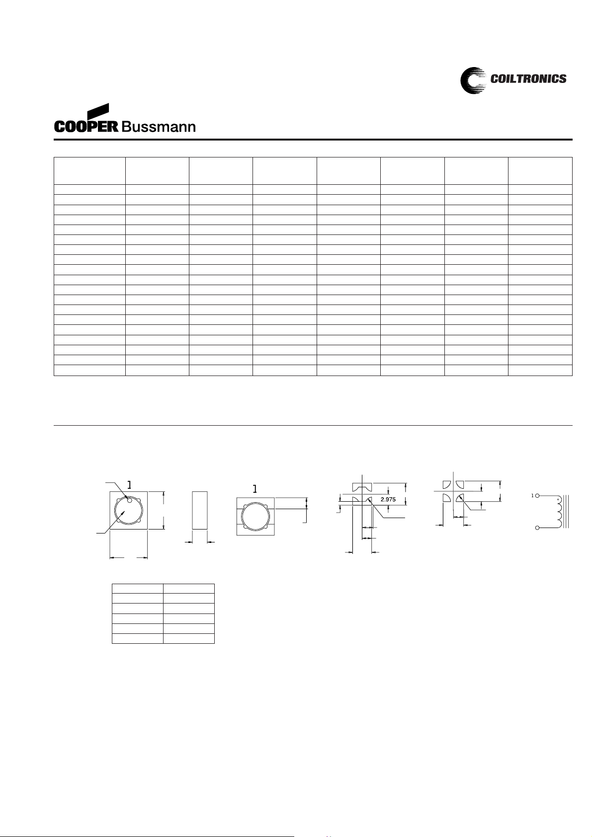
Mechanical Diagrams
TOP VIE
W
BOTTOM VIE
W
RECOMMENDED PCB LAY
OUT
SC
HEMATI
C
5.2
M
ax
5.2
Max
a
H
1.5 Typ
.
Ref
.
S
IDE VIE
W
identifi
er
Part markin
g
(
Note A
)
R2.2
50
2.97
5
5.950
2.975
4 PAD LAYOUT
R2.2
50
5.95
1.
0
2.975
5.15
2.575
2 PAD LAY
OUT
5.950
(
see chart below
)
Part Number Rated OCL (1) Part Irms (2) Isat (3) DCR (4) Volt
Inductance +/-20% Marking Amperes Amperes (Ω)u-sec
(µH) (µH) Typ. T yp.
SD25-3R3 3.30 3.43 F 2.64 2.21 0.0384 5.78
SD25-4R7 4.70 5.03 G 2.39 1.83 0.0467 6.99
SD25-6R8 6.80 6.93 H 2.19 1.56 0.0556 8.21
SD25-8R2 8.20 7.99 J 1.92 1.45 0.0724 8.82
SD25-100 10.0 10.35 K 1.80 1.27 0.0824 10.03
SD25-150 15.0 14.45 L 1.67 1.08 0.0956 11.86
SD25-220 22.0 22.81 M 1.34 0.857 0.1478 14.90
SD25-330 33.0 33.07 N 1.11 0.711 0.2149 17.94
SD25-470 47.0 47.89 O 0.919 0.592 0.3156 21.58
SD25-680 68.0 68.64 P 0.741 0.482 0.4850 25.84
SD25-820 82.0 82.17 Q 0.713 0.441 0.5242 28.27
SD25-101 100 100.79 R 0.670 0.398 0.5937 31.31
SD25-151 150 148.4 S 0.553 0.328 0.8723 38.00
SD25-221 220 222.4 T 0.446 0.268 1.34 46.51
SD25-331 330 332.2 U 0.359 0.219 2.07 56.85
SD25-471 470 472.4 V 0.293 0.184 3.10 67.79
SD25-681 680 677.2 W 0.262 0.154 3.88 81.17
SD25-821 820 826.7 X 0.230 0.139 5.04 89.68
SD25-102 1000 1003.4 Y 0.216 0.126 5.70 98.80
Series HT
SD10 1.0mm max
SD12 1.2mm max
SD18 1.8mm max
SD20 2.0mm max
SD25 2.5mm max
(1) Open Circuit Inductance Test Parameters: 100KHz, 0.25Vrms, 0.0Adc.
(2) RMS current for an approximate ∆T of 40°C without core loss.It is
recommended that the temperature of the part not exceed 125°C.
(3) Peak current for approximate 30% roll off at 20°C.
(4) DCR limits @ 20°C.
5) Applied Volt-Time product (V-uS) across the inductor at 100kHz necessary to
generate a core loss equal to 10% of the total losses for 40°C temperature rise.
®
SD Series
High Power Density,
Low Profile, Shielded Inductors
SD Series
A) Part Marking: Line 1:(1st digit indicates the inductance value per part marking
designator in chart above)
(2nd digit is a bi-weekly production date code)
(3rd digit is the last digit of the year produced)
Line 2: 12 (indicates the product size code)
Page 4

Direction of f
eed
K
o
SECTIO
N A-
A
1.5 Di
a
Bo
Ao
8.0
4.
00
2.00± 0.
05
1.5 Dia
.
+0.1/-0.
0
1.7
5
5.50
12.
0
+/-0.3
0
SD20/25 Series
Dimensions are in millimeters.
Direction of feed
Ko
SECTION A-A
1.5 Dia
min.
Bo
Ao
8.0
4.00
2.00 ± 0.05
1.5 Dia.
+0.1/-0.0
A
A
1.75
5.50
12.0
+/-0.3
1
2
SD12/18 Series
Packaging Information
ACTUAL SIZE
SD12
ACTUAL SIZE
SD18
ACTUAL SIZE
SD20
ACTUAL SIZE
SD25
®
SD Series
High Power Density,
Low Profile, Shielded Inductors
Ao=5.45mm
Bo=5.45mm
Ko=2.00mm
Parts packaged on 13" Diameter reel,
3,800 parts per reel.
Direction of f
eed
K
o
SECTIO
N A-
A
1.5 Di
a
Bo
Ao
8.0
4.
00
2.00
± 0.
05
1.5 Dia
.
+0.1/-0.
0
1.7
5
5.50
12.
0
+/-0.3
0
SD10 Series
ACTUAL SIZE
SD10
Ao=5.45mm
Bo=5.45mm
Ko=1.20mm
Parts packaged on 13" Diameter reel,
3,800 parts per reel.
Ao=5.45mm
Bo=5.45mm
Ko=2.70mm
Parts packaged on 13" Diameter reel,
2,900 parts per reel.
Page 5

®
SD Series
High Power Density,
Low Profile, Shielded Inductors
DC Current vs.Temperature
SD12-330
0.0
10.0
20.0
30.0
40.0
50.0
60.0
70.0
80.0
90.0
100.0
0.00 0.10 0.20 0.30 0.40 0.50 0.60 0.70 0.80
Idc (A)
Temperature Rise (Deg. C)
SD12-470
0.0
10.0
20.0
30.0
40.0
50.0
60.0
70.0
80.0
90.0
100.0
0.00 0.10 0.20 0.30 0.40 0.50 0.60 0.70
Idc (A)
Temperature Rise (Deg. C)
SD10-220
0.0
10.0
20.0
30.0
40.0
50.0
60.0
70.0
80.0
90.0
100.0
0.00 0.10 0.20 0.30 0.40 0.50 0.60 0.70 0.80
Idc (A)
Temperature Rise (Deg. C)
SD10-471
0.0
10.0
20.0
30.0
40.0
50.0
60.0
70.0
80.0
90.0
100.0
0.00 0.05 0.09 0.14 0.18 0.23
Idc (A)
Temperature Rise (Deg. C)
SD18-100
0.0
10.0
20.0
30.0
40.0
50.0
60.0
70.0
80.0
90.0
100.0
0.0 0.2 0.4 0.6 0.8 1.0 1.2 1.4 1.6 1.8 2.0
Idc (A)
Temperature Rise (Deg. C)
SD18-101
0.0
10.0
20.0
30.0
40.0
50.0
60.0
70.0
80.0
90.0
100.0
0.00 0.10 0.20 0.30 0.40 0.50 0.60 0.70 0.80
Idc (A)
Temperature Rise (Deg. C)
SD20-100
0.0
10.0
20.0
30.0
40.0
50.0
60.0
70.0
80.0
90.0
100.0
0.0 0.4 0.8 1.2 1.6 2.0 2.4
Idc (A)
Temperature Rise (Deg. C)
SD20-101
0.0
10.0
20.0
30.0
40.0
50.0
60.0
70.0
80.0
90.0
100.0
0.00 0.10 0.20 0.30 0.40 0.50 0.60 0.70 0.80
Idc (A)
Temperature Rise (Deg. C)
SD25-100
0.0
10.0
20.0
30.0
40.0
50.0
60.0
70.0
80.0
90.0
100.0
0.0 0.5 1.0 1.5 2.0 2.5 3.0
Idc (A)
Temperature Rise (Deg. C)
SD25-101
0.0
10.0
20.0
30.0
40.0
50.0
60.0
70.0
80.0
90.0
100.0
0.00 0.20 0.40 0.60 0.80 1.00 1.20
Idc (A)
Temperature Rise (Deg. C)
Page 6

Rolloff
Core Loss
OCL vs Isat
SD10
0
10
20
30
40
50
60
70
80
90
100
0102030405060708090100 110 120 130 140
% of Isat
OCL (%)
OCL vs Isat
SD12
0
10
20
30
40
50
60
70
80
90
100
0102030405060708090100 110 120
% of Isat
OCL (%)
OCL vs Isat
SD18
0
10
20
30
40
50
60
70
80
90
100
0102030405060708090100 110 120 130 140 150 160
% of Isat
OCL (%)
OCL vs Isat
SD20
0
10
20
30
40
50
60
70
80
90
100
0102030405060708090100110 120 130 140 150 160 170
% of Isat
OCL (%)
OCL vs Isat
SD25
0
10
20
30
40
50
60
70
80
90
100
0102030405060708090100 110 120 130 140 150
% of Isat
OCL (%)
Irms DERATING WITH CORE LOSS
% of Applied Volt-µSecond
% of Losses from Irms (maximum)
®
SD Series
High Power Density,
Low Profile, Shielded Inductors
Page 7

®
SD Series
High Power Density,
Low Profile, Shielded Inductors
Part Number Rated OCL (1) Part Irms (2) Isat (3) DCR (4) Volt
Inductance +/-20% Marking Amperes Amperes (Ω)u-sec
(µH) (µH) Typ. T yp.
SD52-1R2 1.20 1.20 A 2.33 3.14 0.0279 1.49
SD52-2R2 2.20 2.20 B 1.98 2.30 0.0385 2.03
SD52-3R5 3.50 3.50 C 1.73 1.82 0.0503 2.57
SD52-4R7 4.70 4.70 D 1.63 1.64 0.0568 2.84
SD52-6R8 6.80 6.80 E 1.39 1.28 0.0777 3.65
SD52-100 10.0 10.0 F 1.11 1.11 0.1215 4.19
SD52-150 15.0 15.0 G 0.97 0.88 0.1618 5.27
SD52-220 22.0 22.0 H 0.86 0.73 0.2042 6.35
SD52-270 27.0 27.0 J 0.73 0.65 0.2864 7.16
SD52-330 33.0 33.0 K 0.70 0.61 0.3074 7.70
SD52-470 47.0 47.0 L 0.58 0.50 0.4465 9.32
SD52-680 68.0 68.0 M 0.47 0.42 0.6829 11.21
SD52-101 100 100 N 0.39 0.35 1.0000 13.37
RECOMMENDED PCB LAY
OUT
SC
HEMATI
C
TOP VIE
W
2.
0
2 plc
s
6.0
1.
3
2 plc
s
5.2 max
5.2 max
Pin #1 indicato
r
Part markin
g
(
See note A
)
BOTTOM VIE
W
S
IDE VIE
W
2.0 max
m
5.6 max
m
0.65
±
0.10
SD52 Series
A) Part Marking: Line 1:(1st digit indicates the inductance value per part marking
designator in chart above)
(2nd digit is a bi-weekly production date code)
(3rd digit is the last digit of the year produced)
Line 2: 12 (indicates the product size code)
Mechanical Diagrams
Dimensions are in millimeters.
Direction of f
eed
K
o
SECTIO
N A-
A
1.5 Di
a
Bo
Ao
8.0
4.
00
2.00± 0.
05
1.5 Dia
.
+0.1/-0.
0
1.7
5
5.50
12.
0
+/-0.3
0
3.0
SD52 Series
ACTUAL SIZE
SD52
Ao=5.72mm
Bo=5.72mm
Ko=2.30mm
Parts packaged on 13" Diameter reel,
3,500 parts per reel.
(1) Open Circuit Inductance Test Parameters: 100KHz, 0.25Vrms, 0.0Adc.
(2) RMS current for an approximate ∆T of 40°C without core loss.It is
recommended that the temperature of the part not exceed 125°C.
(3) Peak current for approximate 30% roll off at 20°C.
(4) DCR limits @ 20°C.
5) Applied Volt-Time product (V-uS) across the inductor at 100kHz necessary to
generate a core loss equal to 10% of the total losses for 40°C temperature rise.
Packaging Information
Page 8

®
SD Series
High Power Density,
Low Profile, Shielded Inductors
OCL vs Isat
SD52
0
10
20
30
40
50
60
70
80
90
100
0102030405060708090100 110 120 130 140
% of Isat
OCL (%)
Rolloff
DC Current vs.Temperature
SD52-101
0.0
10.0
20.0
30.0
40.0
50.0
60.0
70.0
80.0
90.0
100.0
0.00 0.10 0.20 0.30 0.40 0.50 0.60 0.70
Idc (A)
Temperature Rise (Deg. C)
SD52-1R2
0.0
10.0
20.0
30.0
40.0
50.0
60.0
70.0
80.0
90.0
100.0
0.0 0.5 1.0 1.5 2.0 2.5 3.0 3.5 4.0
Idc (A)
Temperature Rise (Deg. C)
Visit us on the Web at www.cooperET.com
3601 Quantum Boulevard Boynton Beach, Florida 33426-8638
Tel: +1-561-752-5000 Toll Free:+1-888-414-2645 Fax:+1-561-742-1178
This bulletin is intended to present product design solutions and technical information that will help the end user with design applications. Cooper
Electronic Technologies reserves the right, without notice, to change design or construction of any products and to discontinue or limit distribution of
any products. Cooper Electronic Technologies also reserves the right to change or update, without notice, any technical information contained in this
bulletin. Once a product has been selected, it should be tested by the user in all possible applications.
PM-4311 1/03
© Cooper Electronic
Technologies 2003
 Loading...