

Page 1
查询S2006D供应商
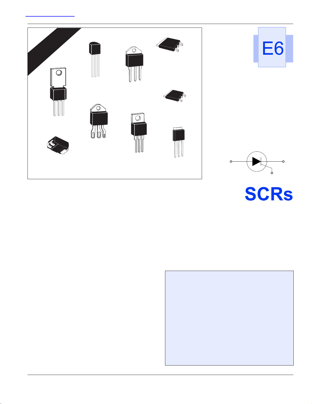
Selected Packages*
File #E71639
U.L. RECOGNIZED
TO-202
TO-92
*TO-218X
*TO-218
TO-263
2
Pak
D
TO-252
D-Pak
3-lead
Compak
E6
*TO-220
General Description
The Teccor line of thyristor SCR semi-conductors are half-wave,
unidirectional, gate-controlled rectifiers which complement Teccor's line of sensitive SCRs. Teccor offers devices with ratings of
1 A to 70 A and 200 V to 1000 V, with gate sensitivities from
10 mA to 50 mA. If gate currents in the 12 µA to 500 µA ranges
are required, see “Sensitive SCRs” section of this catalog.
Three packages are offered in electrically isolated construction
where the case or tab is internally isolated to allow the use of
low-cost assembly and convenient packaging techniques.
The Teccor line of SCRs features glass-passivated junctions to
ensure long-term reliability and parameter stability. Teccor’s
glass offers a rugged, reliable barrier against junction contamination.
Variations of devices covered in this data sheet are available for
custom design applications. Consult the factory for more information.
TO-251
V-Pak
AK
G
(1 A to 70 A)
Features
• Electrically-isolated package
• High voltage capability — 200 V to 1000 V
• High surge capability — up to 950 A
• Glass-passivated chip
Compak SCR
• Surface mount package — 1 A series
• New small profile three-leaded Compak package
• Packaged in embossed carrier tape with 2,500
devices per reel
• Can replace SOT-223
©2002 Teccor Electronics E6 - 1 http://www.teccor.com
Thyristor Product Catalog +1 972-580-7777
Page 2
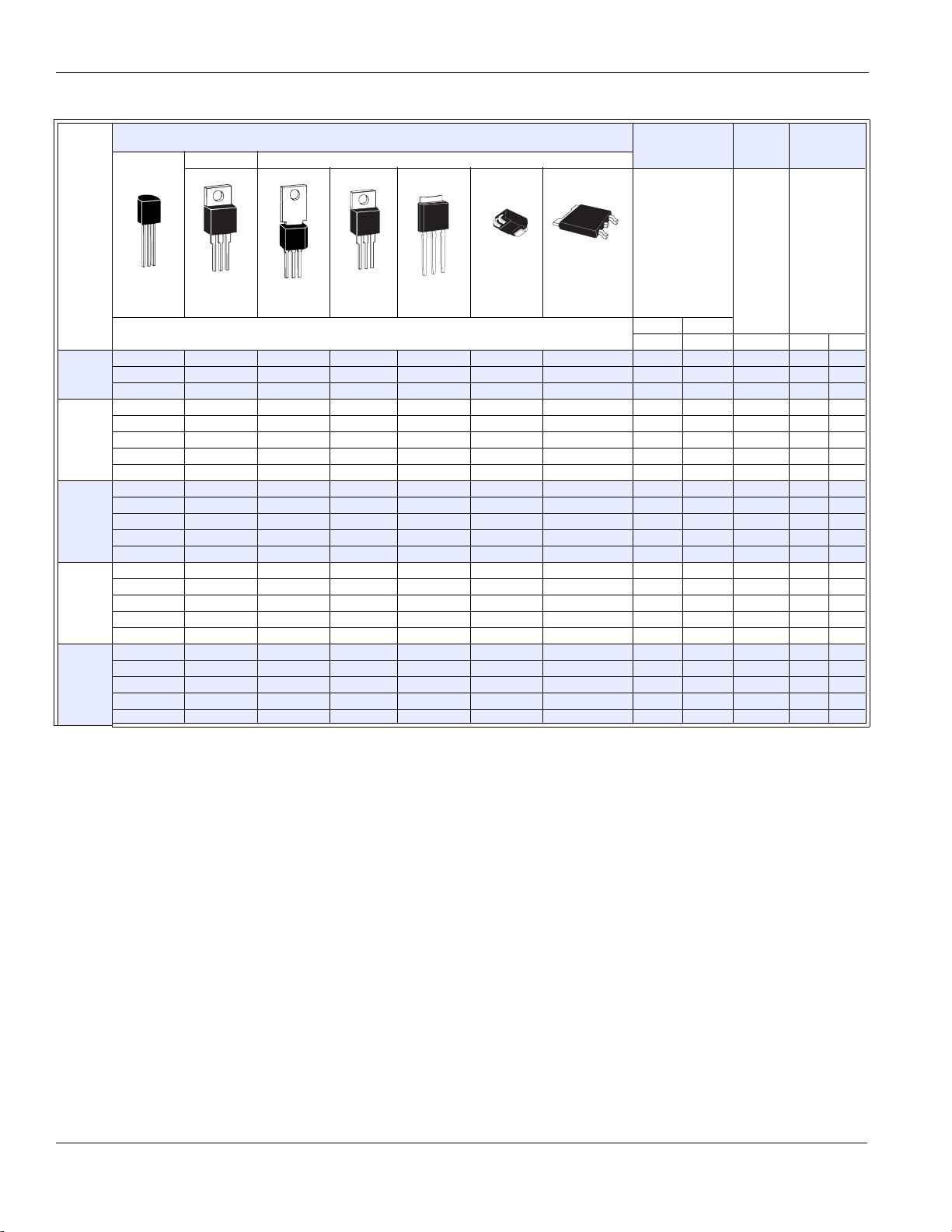
SCRs Data Sheets
TYPE
1A
6A
8A
10 A
12 A
Part Number
Isolated Non-isolated
A
A
K
G
TO-92
S201E S2N1 1 0.64 200 1 10
S401E S4N1 1 0.64 400 1 10
S601E S6N1 1 0.64 600 1 10
G
K
A
TO-220 TO-202
S2006L S2006F1 S2006V S2006D 6 3.8 200 1 15
S4006L S4006F1 S4006V S4006D 6 3.8 400 1 15
S6006L S6006F1 S6006V S6006D 6 3.8 600 1 15
S8006L S8006V S8006D 6 3.8 800 1 15
SK006L SK006V SK006D 6 3.8 1000 1 15
S2008L S2008F1 S2008R S2008V S2008D 8 5.1 200 1 15
S4008L S4008F1 S4008R S4008V S4008D 8 5.1 400 1 15
S6008L S6008F1 S6008R S6008V S6008D 8 5.1 600 1 15
S8008L S8008R S8008V S8008D 8 5.1 800 1 15
SK008L SK008R SK008V SK008D 8 5.1 1000 1 15
S2010L S2010F1 S2010R S2010V S2010D 10 6.4 200 1 15
S4010L S4010F1 S4010R S4010V S4010D 10 6.4 400 1 15
S6010L S6010F1 S6010R S6010V S6010D 10 6.4 600 1 15
S8010L S8010R S8010V S8010D 10 6.4 800 1 15
SK010L SK010R SK010V SK010D 10 6.4 1000 1 15
K
G
A
See “Package Dimensions” section for variations. (11)
A
G
K
A
TO-220
S2012R S2012V S2012D 12 7.6 200 1 20
S4012R S4012V S4012D 12 7.6 400 1 20
S6012R S6012V S6012D 12 7.6 600 1 20
S8012R S8012V S8012D 12 7.6 800 1 20
SK012R SK012V SK012D 12 7.6 1000 1 20
A
G
K
G
K
A
TO-251
V-Pak Compak
A
A
G
A
K
TO-252
D-Pak
I
T
(1) (2) (15)
Amps
I
T(RMS)IT(AV)
MAX MAX MIN MIN MAX
V
& V
DRM
Volts
RRM
I
GT
(4)
mAmps
Specific Test Conditions
di/dt — Maximum rate-of-rise of on-state current; IGT = 150 mA with
£ 0.1 µs rise time
dv/dt — Critical rate of applied forward voltage
2
t — RMS surge (non-repetitive) on-state current for period of 8.3 ms
I
for fusing
and I
I
DRM
V
Igt — dc gate trigger current; VD = 12 V dc; RL = 60 W for 1 to 16 A
devices and 30 W for 20 to 70 A devices
I
— Peak gate current
GM
I
— dc holding current; gate open
H
— Maximum on-state current
I
T
I
— Peak one-cycle forward surge current
TSM
P
G(AV)
— Peak gate power dissipation
P
GM
t
— Gate controlled turn-on time; gate pulse = 100 mA; minimum
gt
— Peak off-state forward and reverse current at V
RRM
RRM
— Average gate power dissipation
DRM
and
and V
V
DRM
V
— DC gate trigger voltage; VD = 12 V dc; RL = 60 W for 1 to 16 A
gt
devices and 30 W for 20 to 70 A devices
— Peak on-state voltage at maximum rated RMS current
V
TM
General Notes
• All measurements are made at 60 Hz with a resistive load at an
ambient temperature of +25 °C unless otherwise specified.
• Operating temperature range (T
devices and -40 °C to +125 °C for all other packages.
• Storage temperature range (T
devices, -40 °C to +150 °C for TO-202 and TO-220 devices, and
-40 °C to +125 °C for all others.
• Lead solder temperature is a maximum of 230 °C for 10 seconds
maximum; ³1/16" (1.59 mm) from case.
• The case temperature (T
outline drawings in the “Package Dimensions” sectionof this
catalog.
— Repetitive peak off-state forward and reverse voltage
RRM
) is -65 °C to +125 °C for TO-92
J
) is -65 °C to +150 °C for TO-92
S
) is measured as shown on dimensional
C
width = 15 µs with rise time £ 0.1 µs
— Circuit commutated turn-off time
t
q
http://www.teccor.com E6 - 2 ©2002 Teccor Electronics
+1 972-580-7777 Thyristor Product Catalog
Page 3
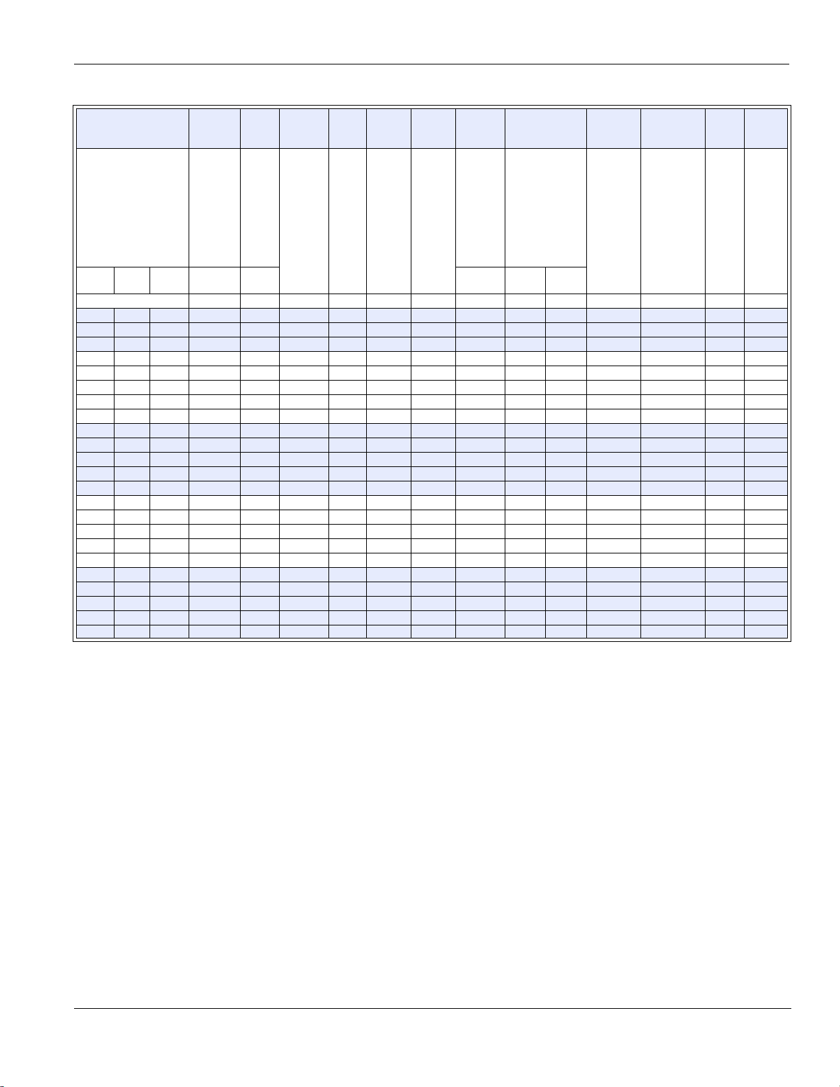
Data Sheets SCRs
I
DRM
& I
(14)
RRM
V
(3)
TM
V
(8)
(17)
I
I
GT
H
(5) (13)
GM
(12)
P
GMPG(AV)ITSM
(12)
(6) (10)
dv/dt I2t di/dt
t
(7)
t
gt
q
(9) (10)
mAmps
=
TC =
T
C
25 °C
100 °C
0.01 0.2 0.5 1.6 1.5 30 1.5 15 0.3 30/25 40 20 3.7 50 2 35
0.01 0.2 0.5 1.6 1.5 30 1.5 15 0.3 30/25 40 20 3.7 50 2 35
0.01 0.2 0.5 1.6 1.5 30 1.5 15 0.3 30/25 40 20 3.7 50 2 35
0.01 0.2 0.5 1.6 1.5 30 2 20 0.5 100/83 350 250 41 100 2 35
0.01 0.2 0.5 1.6 1.5 30 2 20 0.5 100/83 350 250 41 100 2 35
0.01 0.2 0.5 1.6 1.5 30 2 20 0.5 100/83 300 225 41 100 2 35
0.01 0.2 0.5 1.6 1.5 30 2 20 0.5 100/83 250 200 41 100 2 35
0.02 3 1.6 1.5 30 2 20 0.5 100/83 100 41 100 2 35
0.01 0.2 0.5 1.6 1.5 30 2 20 0.5 100/83 350 250 41 100 2 35
0.01 0.2 0.5 1.6 1.5 30 2 20 0.5 100/83 350 250 41 100 2 35
0.01 0.2 0.5 1.6 1.5 30 2 20 0.5 100/83 300 225 41 100 2 35
0.01 0.2 0.5 1.6 1.5 30 2 20 0.5 100/83 250 200 41 100 2 35
0.02 3 1.6 1.5 30 2 20 0.5 100/83 100 41 100 2 35
0.01 0.2 0.5 1.6 1.5 30 2 20 0.5 100/83 350 250 41 100 2 35
0.01 0.2 0.5 1.6 1.5 30 2 20 0.5 100/83 350 250 41 100 2 35
0.01 0.2 0.5 1.6 1.5 30 2 20 0.5 100/83 300 225 41 100 2 35
0.02 0.5 1 1.6 1.5 30 2 20 0.5 100/83 250 200 41 100 2 35
0.02 3 1.6 1.5 30 2 20 0.5 100/83 100 41 100 2 35
0.01 0.5 1 1.6 1.5 40 2 20 0.5 120/100 350 250 60 100 2 35
0.01 0.5 1 1.6 1.5 40 2 20 0.5 120/100 350 250 60 100 2 35
0.01 0.5 1 1.6 1.5 40 2 20 0.5 120/100 300 225 60 100 2 35
0.02 0.5 1 1.6 1.5 40 2 20 0.5 120/100 250 200 60 100 2 35
0.02 3 1.6 1.5 40 2 20 0.5 120/100 100 60 100 2 35
TC =
125 °C
MAX MAX MAX MAX MIN MIN TYP MAX
Volts
TC =
25 °C
Vol ts
TC =
25 °C
mAmps
Amps
Watts Watts
Amps Volts/µSec
T
=
60/50 Hz
C
100 °C
TC =
125 °C
2
Amps
Sec Amps/µSec
µSec
µSec
Electrical Specification Notes
(1) See Figure E6.5 through Figure E6.16 for current rating at
specified operating case temperature.
(2) See Figure E6.1 and Figure E6.2 for free air current rating.
(3) See Figure E6.19 and Figure E6.20 for instantaneous on-state
current versus on-state voltage (typical).
(4) See Figure E6.18 for I
(5) See Figure E6.17 for I
(6) For more than one full cycle rating, see Figure E6.23.
(7) See Figure E6.22 for t
(8) See Figure E6.21 for V
(9) Test conditions are as follows:
= 1 A for 1 A devices and 2 A for all other devices
•I
T
versus TC.
GT
versus TC.
H
versus IGT.
gt
versus TC.
GT
(11) See package outlines for lead form configuration. When ordering
special lead forming, add type number as suffix to part number.
(12) Pulse width £10 µs
(13) Initial on-state current = 200 mA dc for 1 A through 16 A devices;
400 mA dc for 20 A through 70 A devices.
= TJ for test conditions in off state.
(14) T
C
(15) The R, K, or M package rating is intended for high surge condition
use only and not recommended for ³50 A rms continuous current
use since narrow pin lead temperature can exceed PCB solder melting
temperature. Teccor's J package or W package is recommended
for ³50 A rms continuous current requirements.
(16) For various durations of an exponentially decaying current
waveform, see Figure E6.3 and Figure E6.4. (t
is defined as
W
5 time constants.)
(17) Minimum non-trigger V
at 125 °C is 0.2 V.
GT
• Pulse duration = 50 µs, dv/dt = 20 V/µs, di/dt = -10 A/µs for 1 A
devices, and -30 A/µs for other devices
•I
= 200 mA at turn-on
GT
(10) See Figure E6.5 through Figure E6.10 for maximum allowable
case temperatures at maximum rated current.
©2002 Teccor Electronics E6 - 3 http://www.teccor.com
Thyristor Product Catalog +1 972-580-7777
Page 4
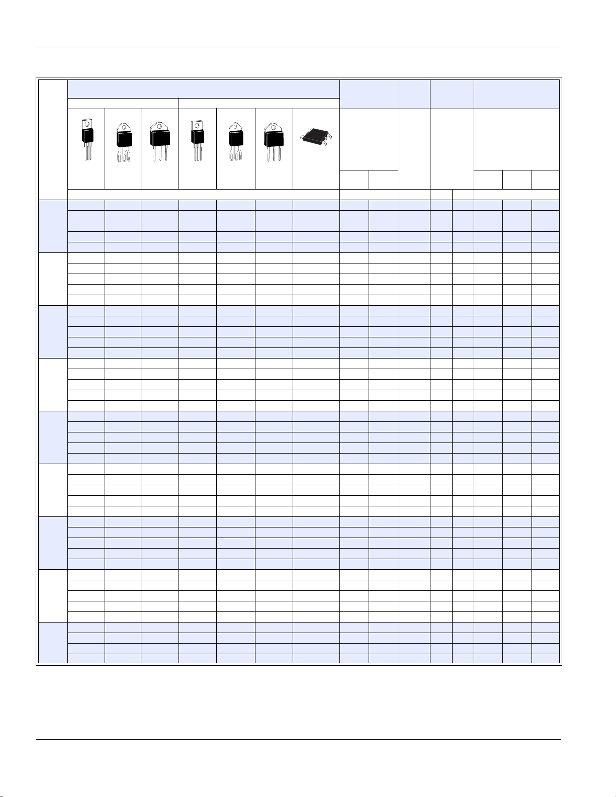
SCRs Data Sheets
Part Number
Isolated Non-isolated
A
A
K
G
A
A
A
G
A
K
G
A
K
TO-263
2
Pak
D
TYPE
A
G
K
K
A
G
A
G
A
K
A
G
K
A
TO-220 TO-218X TO-218 TO-220 TO-218X TO-218
See “Package Dimensions” section for variations. (11) MAX MIN MIN MAX MAX
S2015L 15 9.5 200 1 30 0.01 0.5 1
15 A
S4015L 15 9.5 400 1 30 0.01 0.5 1
S6015L 15 9.5 600 1 30 0.01 0.5 1
S8015L 15 9.5 800 1 30 0.02 1 2
SK015L 15 9.5 1000 1 30 0.02 3
S2016R S2016N 16 10 200 1 30 0.01 0.5 1
16 A
S4016R S4016N 16 10 400 1 30 0.01 0.5 1
S6016R S6016N 16 10 600 1 30 0.01 0.5 1
S8016R S8016N 16 10 800 1 30 0.02 1 2
SK016R SK016N 16 10 1000 1 30 0.02 3
S2020L 20 12.8 200 1 30 0.01 0.5 1
20 A
S4020L 20 12.8 400 1 30 0.01 0.5 1
S6020L 20 12.8 600 1 30 0.01 0.5 1
S8020L 20 12.8 800 1 30 0.02 1.0 2
SK020L 20 12.8 1000 1 30 0.02 3
S2025L S2025R S2025N 25 16 200 1 35 0.01 1 2
25 A
S4025L S4025R S4025N 25 16 400 1 35 0.01 1 2
S6025L S6025R S6025N 25 16 600 1 35 0.01 1 2
S8025L S8025R S8025N 25 16 800 1 35 0.02 1.5 3
SK025L SK025R SK025N 25 16 1000 1 35 0.02 3
S2035J S2035K 35 22 200 5 40 0.01 1 2
35 A
S4035J S4035K 35 22 400 5 40 0.01 1 2
S6035J S6035K 35 22 600 5 40 0.01 1 2
S8035J S8035K 35 22 800 5 40 0.02 1.5 3
SK035K 35 22 1000 5 40 0.02 3
S2040R S2040N 40 25 200 5 40 0.01 1 2
40 A
S4040R S4040N 40 25 400 5 40 0.01 1 2
S6040R S6040N 40 25 600 5 40 0.01 1 2
S8040R S8040N 40 25 800 5 40 0.02 1.5 3
SK040R SK040N 40 25 1000 5 40 0.03 5
S2055R S2055W S2055M S2055N 55 35 200 5 40 0.01 1 2
55 A
S4055R S4055W S4055M S4055N 55 35 400 5 40 0.01 1 2
S6055R S6055W S6055M S6055N 55 35 600 5 40 0.01 1 2
S8055R S8055W S8055M S8055N 55 35 800 5 40 0.02 1.5 3
SK055R SK055M SK055N 55 35 1000 5 40 0.03 5
S2065J S2065K 65 41 200 5 50 0.02 1.5 3
65 A
S4065J S4065K 65 41 400 5 50 0.02 1.5 3
S6065J S6065K 65 41 600 5 50 0.02 1.5 3
S8065J S8065K 65 41 800 5 50 0.02 2 5
SK065K 65 41 1000 5 50 0.03 5
S2070W 70 45 200 5 50 0.02 1.5 3
70 A
S4070W 70 45 400 5 50 0.02 1.5 3
S6070W 70 45 600 5 50 0.02 1.5 3
S8070W 70 45 800 5 50 0.02 2 5
See “General Notes” on page E6 - 2 and “Electrical Specification Notes” on page E6 - 3.
I
T
(1) (15)
Amps
I
T(RMS)IT(AV)
V
DRM
V
RRM
Volts
&
I
GT
(4)
mAmps
TC =
25 °C
I
DRM
& I
(14)
mAmps
TC =
100 °C
RRM
TC =
125 °C
http://www.teccor.com E6 - 4 ©2002 Teccor Electronics
+1 972-580-7777 Thyristor Product Catalog
Page 5

Data Sheets SCRs
V
TM
(3)
Vol ts
T
= 25 °C TC = 25 °C 60/50 Hz
C
MAX MAX MAX MIN MIN TYP MAX
1.6 1.5 40 3 30 0.6 225/188 450 350 210 125 2 35
1.6 1.5 40 3 30 0.6 225/188 450 350 210 125 2 35
1.6 1.5 40 3 30 0.6 225/188 425 325 210 125 2 35
1.6 1.5 40 3 30 0.6 225/188 400 300 210 125 2 35
1.6 1.5 40 3 30 0.6 225/188 200 210 125 2 35
1.6 1.5 40 3 30 0.6 225/188 450 350 210 125 2 35
1.6 1.5 40 3 30 0.6 225/188 450 350 210 125 2 35
1.6 1.5 40 3 30 0.6 225/188 425 325 210 125 2 35
1.6 1.5 40 3 30 0.6 225/188 400 300 210 125 2 35
1.6 1.5 40 3 30 0.6 225/188 200 210 125 2 35
1.6 1.5 40 3 30 0.6 300/255 450 350 374 125 2 35
1.6 1.5 40 3 30 0.6 300/255 450 350 374 125 2 35
1.6 1.5 40 3 30 0.6 300/255 425 325 374 125 2 35
1.6 1.5 40 3 30 0.6 300/255 400 300 374 125 2 35
1.6 1.5 40 3 30 0.6 300/255 200 374 125 2 35
1.6 1.5 50 3.5 35 0.8 350/300 450 350 510 150 2 35
1.6 1.5 50 3.5 35 0.8 350/300 450 350 510 150 2 35
1.6 1.5 50 3.5 35 0.8 350/300 425 325 510 150 2 35
1.6 1.5 50 3.5 35 0.8 350/300 400 300 510 150 2 35
1.6 1.5 50 3.5 35 0.8 350/300 200 510 150 2 35
1.8 1.5 50 3.5 35 0.8 500/425 450 350 1035 150 2 35
1.8 1.5 50 3.5 35 0.8 500/425 450 350 1035 150 2 35
1.8 1.5 50 3.5 35 0.8 500/425 425 325 1035 150 2 35
1.8 1.5 50 3.5 35 0.8 500/425 400 300 1035 150 2 35
1.8 1.5 50 3.5 35 0.8 500/425 200 1035 150 2 35
1.8 1.5 60 3.5 35 0.8 520/430 650 550 1122 175 2.5 35
1.8 1.5 60 3.5 35 0.8 520/430 650 550 1122 175 2.5 35
1.8 1.5 60 3.5 35 0.8 520/430 600 500 1122 175 2.5 35
1.8 1.5 60 3.5 35 0.8 520/430 500 475 1122 175 2.5 35
1.8 1.5 60 3.5 35 0.8 520/430 250 1122 175 2.5 35
1.8 1.5 60 4 40 0.8 650/550 650 550 1750 175 2.5 35
1.8 1.5 60 4 40 0.8 650/550 650 550 1750 175 2.5 35
1.8 1.5 60 4 40 0.8 650/550 600 500 1750 175 2.5 35
1.8 1.5 60 4 40 0.8 650/550 500 475 1750 175 2.5 35
1.8 1.5 60 4 40 0.8 650/550 250 1750 175 2.5 35
1.8 2 80 5 50 1 950/800 650 550 3745 200 2.5 35
1.8 2 80 5 50 1 950/800 650 550 3745 200 2.5 35
1.8 2 80 5 50 1 950/800 600 500 3745 200 2.5 35
1.8 2 80 5 50 1 950/800 500 475 3745 200 2.5 35
1.8 2 80 5 50 1 950/800 250 3745 200 2.5 35
1.8 2 80 5 50 1 950/800 650 550 3745 200 2.5 35
1.8 2 80 5 50 1 950/800 650 550 3745 200 2.5 35
1.8 2 80 5 50 1 950/800 600 500 3745 200 2.5 35
1.8 2 80 5 50 1 950/800 500 475 3745 200 2.5 35
V
GT
(8) (17)
Vol ts
I
H
(5) (13)
mAmps
I
GM
(12)
Amps
P
(12)
Watts Wat ts
GM
P
G(AV)
I
TSM
(6) (10) (16)
Amps Volts/µSec
=
T
C
100 °C
dv/dt I2t di/dt
TC =
125 °C
2
Amps
Sec Amps/µSec
t
gt
(7)
µSec
See “General Notes” on page E6 - 2 and “Electrical Specification Notes” on page E6 - 3.
t
q
(9) (10)
µSec
©2002 Teccor Electronics E6 - 5 http://www.teccor.com
Thyristor Product Catalog +1 972-580-7777
Page 6

SCRs Data Sheets
Pkg.
Code
Typ e
1A
6A
8A
10 A
12 A
15 A
16 A
20 A
25 A
35 A
40 A
55 A
65 A
70 A
Thermal Resistance (Steady State)
[R
R
LF F2 R J W KM D V N
TO-220
Isolated
4.0 [50] 4.3 [45] 9.5 [70] 1.7 2.3 [70]
3.4 3.9 1.8 [40] 1.5 2.0
3.0 3.4 1.6 1.45 1.7
2.5
2.4
2.35 1.0 1.0
TO-202
Type 1
Non-isolated
TO-202
Type 2
Non-isolated
TO-220
Non-isolated
1.5 1.4 1.6
1.3 1.3
0.6 0.6
0.5 0.53 0.53 0.5
qJC
TO-218X
Isolated
0.70 0.70
0.86 0.86
] °C/W (TYP.)
qJA
TO-218X
Non-isolated
See below
0.60
TO-218
Isolated
TO-218
Non-isolated
TO-252
D-Pak
Surface Mount
TO-251AA
V-Pak
Non-isolated
TO-263
2
D
Pak
Non-isolated
Thermal Resistance (Steady State)
R
[R
Package Code CE
qJC
Typ e
1A 35 * 50 [145]
] °C/W (TYP.)
qJA
Compak TO-92
* Mounted on 1cm2 copper foil surface; two-ounce copper foil
Electrical Isolation
Teccor’s isolated SCR packages will withstand a minimum high
potential test of 2500 V ac rms from leads to mounting tab over
the device's operating temperature range. The following table
shows standard and optional isolation ratings.
Electrical Isolation *
from Leads to Mounting Tab
VACRMS
2500
4000
Isolated
Standard Standard Standard
Optional ** N/A N/A
* UL Recognized File #E71639
** For 4000 V isolation, use “V” suffix in part number.
TO-220
TO-218X
Isolated
TO-218
Isolated
http://www.teccor.com E6 - 6 ©2002 Teccor Electronics
+1 972-580-7777 Thyristor Product Catalog
Page 7

Data Sheets SCRs
120
100
) – ˚C
A
80
60
1 A TO-92
CURRENT WAVEFORM: Sinusoidal
LOAD: Resistive or Inductive
CONDUCTION ANGLE: 180˚
FREE AIR RATING
8 A TO-220 (Non-isolated)
6 A TO-220 (Isolated) and
6 A TO-202 (Types 1 and 3)
Maximum Allowable
40
Ambient Temperature (T
20
0.2
0
0.4 0.6 0.8 1.0 1.2 1.4 1.6
RMS On-state Current [I
6 A TO-202
(Types 2 and 4)
and 6 A TO-251
T(RMS)
1.8
] – Amps
2.0
Figure E6.1 Maximum Allowable Ambient Temperature versus
RMS On-state Current
120
100
) – ˚C
A
80
1 A TO-92
60
Maximum Allowable
Ambient Temperature (T
40
20
0.2
0
0.4 0.6 0.8 1.0 1.2 1.4
Average On-state Current [I
CURRENT WAVEFORM: Sinusoidal
LOAD: Resistive or Inductive
CONDUCTION ANGLE: 180˚
FREE AIR RATING
8 A TO-220 (Non-isolated)
6 A TO-220 (Isolated) and
6 A TO-202 (Types 1 and 3)
6 A TO-202
(Types 2 and 4)
and 6 A TO-251
] – Amps
T(AV)
2.2
1.0
0.8
0.6
0.4
0.2
Normalized Peak Current
0
25 50 75 100 125
Case Temperature (TC) – ˚C
Figure E6.4 Peak Capacitor Discharge Current Derating
(6 A through 55 A)
130
120
110
) – ˚C
C
100
90
80
Maximum Allowable
CURRENT WAVEFORM: Sinusoidal
LOAD: Resistive or Inductive
70
CONDUCTION ANGLE: 180˚
Case Temperature (T
CASE TEMPERATURE: Measure as
60
shown on dimensional drawing
50
0 0.4 0.8 1.20.6
1 A Devices
RMS On-state Current [I
T(RMS)
] – Amps
1.00.2
Figure E6.2 Maximum Allowable Ambient Temperature versus
Average On-state Current
1000
) – Amps
TM
300
200
100
I
TM
50
Peak Discharge Current (I
tw = 5 times constants
20
0.5 1.0 2.0 5.0 10 20 50
t
w
55 A Devices
25 A Devices
15 A and 16 A
6 A to 10 A Devices
Devices
12 A Devices
Pulse Current Duration (tw) – ms
Figure E6.3 Peak Capacitor Discharge Current (6 A through 55 A)
Figure E6.5 Maximum Allowable Case Temperature versus
RMS On-state Current (1 A)
130
120
110
) – ˚C
6 A Devices
C
100
90
80
Maximum Allowable
70
Case Temperature (T
60
50
0246 81012
8 A TO-220 (Isolated)
CURRENT WAVEFORM: Sinusoidal
LOAD: Resistive or Inductive
CONDUCTION ANGLE: 180º
CASE TEMPERATURE: Measure as
shown on dimensional drawings
8 A TO-220 (Non-isolated)
TO-251 and TO-252
and 8 A TO-202
RMS On-state Current [I
10 A TO-220 (Isolated)
and 10 A TO-202
] – Amps
T(RMS)
Figure E6.6 Maximum Allowable Case Temperature versus
RMS On-state Current (6 A, 8 A, and 10 A)
©2002 Teccor Electronics E6 - 7 http://www.teccor.com
Thyristor Product Catalog +1 972-580-7777
Page 8

SCRs Data Sheets
130
120
) – ˚C
110
C
10 A TO-220
(Non-isolated)
100
10 A TO-251 and 10 A TO-252
90
80
70
Maximum Allowable
Case Temperature (T
60
50
12 A TO-220 (Non-isolated)
CURRENT WAVEFORM: Sinusoidal
LOAD: Resistive or Inductive
CONDUCTION ANGLE: 180˚
CASE TEMPERATURE: Measure as
shown on dimensional drawing
04 8121620
16 A TO-220 (Non-isolated)
TO-251 and TO-252
and TO-263
RMS On-state Current [I
T(RMS)
] – Amps
20 A TO-220 (Isolated)
Figure E6.7 Maximum Allowable Case Temperature versus
RMS On-state Current (10 A, 12 A, 16 A, and 20 A)
130
120
110
) – ˚C
C
25 A TO-220
100
Maximum Allowable
Case Temperature (T
(Isolated)
90
80
CURRENT WAVEFORM: Sinusoidal
70
LOAD: Resistive or Inductive
CONDUCTION ANGLE: 180
60
CASE TEMPERATURE: Measure
as shown on dimensional drawings
50
25 A TO-220
(Non-isolated)
and TO-263
˚
0 4 8 12162024283236
RMS On-state Current [I
T(RMS)
] – Amps
Figure E6.8 Maximum Allowable Case Temperature versus
RMS On-state Current (25 A and 35 A)
15 A TO-220
(Isolated)
35 A TO-218
(Isolated)
130
120
) – ˚C
C
110
55 A TO-220
100
(Non-isolated)
and TO-263 *
90
* The R, K or M package rating
80
is intended only for high surge
condition use and is not recommended
for >50 A rms continuous
70
current use, since narrow pin lead
temperature can exceed PCB solder
melting temperature. J or W packages
60
are recommended for >50 A rms
continuous current requirements.
Maximum Allowable Case Temperature (T
50
010203040
RMS On-state Current [I
CURRENT WAVEFORM: Sinusoidal
LOAD: Resistive or Inductive
CONDUCTION ANGLE: 180˚
CASE TEMPERATURE: Measure as
shown on dimensional drawings
55 A TO-218AC
(Non-isolated) *
65 A TO-218AC
(Isolated) *
50 60 70 75
] – Amps
T(RMS)
Figure E6.10 Maximum Allowable Case Temperature versus
RMS On-state Current (55 A and 65 A)
130
) – ˚C
C
120
110
100
90
80
70
CURRENT WAVEFORM: Sinusoidal
LOAD: Resistive or Inductive
CONDUCTION ANGLE: 180˚
60
CASE TEMPERATURE: Measure as
shown on dimensional drawings
50
Maximum Allowable Case Temperature (T
0 0.2 0.4 0.6 0.8
Average On-state Current [I
1 A Devices
T(AV)
] – Amps
Figure E6.11 Maximum Allowable Case Temperature versus
Average On-state Current (1 A)
130
120
110
) – ˚C
C
100
65 A TO-218X
90
80
(Isolated)
Maximum Allowable
70
Case Temperature (T
60
50
0 10203040506070
RMS On-state Current [I
CURRENT WAVEFORM: Sinusoidal
LOAD: Resistive or Inductive
CONDUCTION ANGLE: 180˚
CASE TEMPERATURE: Measure as
shown on dimensional drawings
55 A TO-218X
(Non-isolated)
40 A TO-220
(Non-isolated)
and TO-263
T(RMS)
70 A TO-218X
(Non-isolated)
] – Amps
Figure E6.9 Maximum Allowable Case Temperature versus
RMS On-state Current (40 A through 70 A)
130
) – ˚C
C
120
110
6 A TO-220
6 A TO-202
100
90
80
Maximum Allowable Case Temperature (T
12 A TO-220 (Non-isolated)
and TO-251 and TO-252
10 A TO-251
10 A TO-252
6 A TO-251
6 A TO-252
8 A TO-220 (Isolated)
8 A TO-202
8 A TO-220
(Non-isolated)
10 2345678
Average On-state Current [I
CURRENT WAVEFORM: Sinusoidal
LOAD: Resistive or Inductive
CONDUCTION ANGLE: 180˚
CASE TEMPERATURE: Measure as
shown on dimensional drawings
10 A TO-220
(Non-isolated)
10 A TO-220 (Isolated)
and 10 A TO-202
] – Amps
T(AV)
Figure E6.12 Maximum Allowable Case Temperature versus
Average On-state Current (8 A, 10 A, and 12 A)
http://www.teccor.com E6 - 8 ©2002 Teccor Electronics
+1 972-580-7777 Thyristor Product Catalog
Page 9

Data Sheets SCRs
0
130
16 A TO-220 (Non-isolated) and TO-263
120
110
) – ˚C
C
100
90
80
Maximum Allowable
Case Temperature (T
70
60
50
02468101214
10 A TO-220
(Non-isolated)
15 A TO-220
(Isolated)
Average On-state Current [I
CURRENT WAVEFORM: Sinusoidal
LOAD: Resistive or Inductive
CONDUCTION ANGLE: 180˚
CASE TEMPERATURE: Measured
as shown on dimensional drawings
20 A TO-220
(Isolated)
] – Amps
T(AV)
Figure E6.13 Maximum Allowable Case Temperature versus
Average On-state Current (10 A through 20 A)
130
120
) – ˚C
C
110
100
90
25A TO-220 (Isolated)
80
70
60
Maximum Allowable Case Temperature (T
50
0 .4 8 12 16 20 24
25A TO-220 (Non-isolated)
Average On-state Current [I
CURRENT WAVEFORM: Sinusoidal
LOAD: Resistive or Inductive
CONDUCTION ANGLE: 180˚
CASE TEMPERATURE: Measure as
shown on dimensional drawings
35 A TO-218 (Non-isolated)
and TO-263
T(AV)
35 A TO-218 (Isolated)
] – Amps
130
120
110
) – ˚C
C
100
55 A TO-220
(Non-isolated)
and TO-263
90
80
The R, K, or M package
Maximum Allowable
*
rating is intended only for high
surge condition use and is not
70
Case Temperature (T
recommended for >32 A (AV)
continuous current use since narrow
pin lead temperature can exceed PCB
60
solder melting temperature. J or W
packages are recommended for >32 A
(AV) continuous current requirements.
50
CURRENT WAVEFORM: Sinusoidal
LOAD: Resistive or Inductive
CONDUCTION ANGLE: 180˚
CASE TEMPERATURE: Measure
as shown on dimensional drawings
55 A TO-218AC (Non-isolated) *
*
65 A TO-218AC
(Isolated) *
0 102030405
Average On-state Current [I
T(AV)
] – Amps
Figure E6.16 Maximum Allowable Case Temperature versus
Average On-state Current (55 A and 65 A)
2.0
INITIAL ON-STATE CURRENT =
200 mA dc for 1 A to 20 A Devices
and 400 mA dc for 25 A to 70 A Devices
-40 -15 +25 +65 +105 +125
H
I
Ratio of
1.5
= 25 ˚C)
C
(T
1.0
H
I
.5
0
Case Temperature (TC) – ˚C
Figure E6.14 Maximum Allowable Case Temperature versus
Figure E6.17 Normalized dc Holding Current versus Case Temperature
Average On-state Current (25 A and 35 A)
130
120
110
) – ˚C
C
100
90
(Non-isolated)
Maximum Allowable
80
Case Temperature (T
70
60
40 A TO-220
and TO-263
55 A TO-218X
(Non-isolated)
65 A TO-218X
(Isolated)
CURRENT WAVEFORM: Sinusoidal
LOAD: Resistive or Inductive
CONDUCTION ANGLE: 180˚
CASE TEMPERATURE: Measure as
shown on dimensional drawings
70 A TO-218X
(Non-isolated)
50
0 1020304050
Average On-state Current [I
T(AV)
] – Amps
Figure E6.15 Maximum Allowable Case Temperature versus
Average On-state Current (40 A through 70 A)
Figure E6.18 Normalized DC Gate-Trigger Current versus
2.0
1.5
= 25 ˚C)
GT
I
C
(T
1.0
GT
I
0.5
Ratio of
0
-40 -15 +25 +65 +105 +125
Case Temperature
Case Temperature (TC) – ˚C
©2002 Teccor Electronics E6 - 9 http://www.teccor.com
Thyristor Product Catalog +1 972-580-7777
Page 10

SCRs Data Sheets
90
80
TC = 25˚C
70
) – Amps
T
i
60
50
40
30
20
10
Instantaneous On-state Current (
0
0 0.6 0.8 1.0 1.2 1.4 1.6
15 A to 20 A Devices
12 A Devices
6 A to 10 A Devices
25 A Devices
1 A Devices
Instantaneous On-state Voltage (vT) – Volts
Figure E6.19 Instantaneous On-state Current versus On-state Voltage
(Typical) (6 A through 25 A)
Figure E6.21 Normalized DC Gate-trigger Voltage versus
1.5
1.0
= 25 ˚C)
GT
C
V
(T
GT
V
0.5
Ratio of
0
-40 -15 +25 +65 +105 +125
Case Temperature (TC) – ˚C
Case Temperature
200
180
160
TC = 25˚C
140
120
) – Amps
T
i
100
65 A and 70 A Devices
80
Current (
60
Instantaneous On-state
55 A Devices
40
20
0
35 A to 40 A Devices
0 .6 .8 1.0 1.2 1.4 1.6
Instantaneous On-state Voltage (v
) – Volts
T
Figure E6.20 Instantaneous On-state Current versus On-state Voltage
(Typical) (35 A through 70 A)
7
6 A to 12 A Devices
6
5
) – µs
gt
4
1 A Devices
3
Turn-on Time (t
2
1
0
10 20 30 40 50 60 80 100 200
15 A to 35 A Devices
TC = 25˚C
40 A to 70 A Devices
DC Gate Trigger Current (IGT) – mA
Figure E6.22 Typical Turn-on Time versus Gate-trigger Current
http://www.teccor.com E6 - 10 ©2002 Teccor Electronics
+1 972-580-7777 Thyristor Product Catalog
Page 11

Data Sheets SCRs
70 A Devices
65 A TO-218
55 A Devices
25 A Devices
35 A Devices
20 A Devices
16 A Devices
15 A Devices
12 A Devices
10 A Devices
1 A Devices
SUPPLY FREQUENCY: 60 Hz Sinusoidal
LOAD: Resistive
RMS ON-STATE CURRENT: [I
T(RMS)
]: Max-
Rated Value at Specified Case Temperature
Notes:
1) Gate control may be lost during and
immediately following surge current
interval.
2) Overload may not be repeated until
junction temperature has returned to
steady-state rated value.
8 A Devices
6 A Devices
1000
800
600
500
400
) – Amps
300
200
TSM
100
80
60
50
40
30
20
10
8
6
5
4
3
2
Peak Surge (Non-repetitive) On-state Current (I
1
1 23 54 6 7 8 10 20 30 40 60 80100 200 300400 600 1000
Surge Current Duration – Full Cycles
Figure E6.23 Peak Surge Current versus Surge Current Duration
CURRENT WAVEFORM: Half Sine Wave
LOAD: Resistive or Inductive
CONDUCTION ANGLE: 180˚
1.0 A Devices
0
0 0.2 0.4 0.6 0.8
RMS On-state Current [I
T(RMS)
1.0
] – Amps
] – Watts
1.0
D(AV)
0.8
0.6
0.4
Average On-state Power
Dissipation [P
0.2
40 A Devices
18
CURRENT WAVEFORM: Half Sine Wave
16
LOAD: Resistive or Inductive
CONDUCTION ANGLE: 180˚
14
] – Watts
12
D(AV)
10
8
6
Average On-state
4
2
Power Dissipation [P
0
0481216
6 A to 10 A Devices
2 6 10 14 18
RMS On-state Current [I
15 A to 20 A Devices
12 A Devices
T(RMS)
20
] – Amps
Figure E6.24 Power Dissipation (Typical) versus RMS On-state Current
(1 A)
©2002 Teccor Electronics E6 - 11 http://www.teccor.com
Thyristor Product Catalog +1 972-580-7777
Figure E6.25 Power Dissipation (Typical) versus RMS On-state Current
(6 A through 20 A)
Page 12

SCRs Data Sheets
32
CURRENT WAVEFORM: Half Sine Wave
28
LOAD: Resistive or Inductive
CONDUCTION ANGLE: 180˚
24
] x– Watts
20
D(AV)
16
12
Average On-state
8
4
Power Dissipation [P
0
0 8 16 24 32
25 A TO-220 Devices
412202836
RMS On-state Current [I
T(RMS)
35 A Devices
] – Amps
Figure E6.26 Power Dissipation (Typical) versus RMS On-state Current
(25 A and 35 A)
60
CURRENT WAVEFORM: Half Sine Wave
LOAD: Resistive or Inductive
CONDUCTION ANGLE: 180˚
50
40
] – Watts
D(AV)
30
Average On-state
20
Power Dissipation [P
10
0
0 10203040506070
RMS On-state Current [I
65 A and 70 A Devices
40 A and 55 A Devices
] – Amps
T(RMS)
Figure E6.27 Power Dissipation (Typical) versus RMS On-state Current
(40 A through 70 A)
http://www.teccor.com E6 - 12 ©2002 Teccor Electronics
+1 972-580-7777 Thyristor Product Catalog
 Loading...