

Datasheet SCN2652AC2A44, SCN2652AC2F40, SCN2652AC2N40, SCN68652AC2A44, SCN68652AC2F40 Datasheet (Philips)
...Page 1

INTEGRATED CIRCUITS
SCN2652/SCN68652
Multi-protocol communications controller
(MPCC)
Product specification
IC19 Data Handbook
1995 May 01
Page 2

Philips Semiconductors Product specification
SCN2652/SCN68652Multi-protocol communications controller (MPCC)
DESCRIPTION
The SCN2652/68652 Multi-Protocol Communications Controller
(MPCC) is a monolithic n-channel MOS LSI circuit that formats,
transmits and receives synchronous serial data while supporting
bit-oriented or byte control protocols. The chip is TTL compatible,
operates from a single +5V supply, and can interface to a processor
with an 8 or 16-bit bidirectional data bus.
APPLICATIONS
•Intelligent terminals
•Line controllers
•Network processors
•Front end communications
•Remote data concentrators
•Communication test equipment
•Computer to computer links
PIN CONFIGURATION
1
RxC
2
RxSI
3
S/F
4
RxA
5
RxDA
6
RxSA
7
RxE
8
GND
9
10
11
12
13
14
15
16
17
18
19
DIP
TOP VIEW
DB08
DB09
DB10
DB11
DB12
DB13
DB14
DB15
/W
R
A2
A1 A0
40CE
MM
39
TxC
38
TxSQ
37
TxE
36
TxU
35
TxBE
34
TxA
33
RESET
32
V
CC
DB00
31
DB01
30
DB02
29
DB03
28
DB04
27
26
DB05
25
DB06
24
DB07
23
DBEN
22
BYTE
2120
FEA TURES
•DC to 2Mbps data rate
•Bit-oriented protocols (BOP): SDLC, ADCCP, HDLC
•Byte-control protocols (BCP): DDCMP, BISYNC (external CRC)
•Programmable operation
– 8 or 16-bit tri-state data bus
– Error control – CRC or VRC or none
– Character length – 1 to 8 bits for BOP or 5 to 8 bits for BCP
– SYNC or secondary station address comparison for BCP-BOP
– Idle transmission of SYNC/FLAG or MARK for BCP-BOP
•Automatic detection and generation of special BOP control
sequences, i.e., FLAG, ABORT, GA
•Zero insertion and deletion for BOP
•Short character detection for last BOP data character
•SYNC generation, detection, and stripping for BCP
•Maintenance mode for self-testing
•TTL compatible
•Single +5V supply
INDEX
CORNER
NOTE: DB00 is least significant bit, highest number
(that is, DB15, A2) is most significant bit.
6
7
17
18
Pin Function Pin Function
1NC 23NC
2CE 24A0
3 RxC 25 BYTE
4 RxSI 26 DBEN
5 S/F 27 DB07
6 RxA 28 DB06
7 RxDA 29 DB05
8 RxSA 30 DB04
9 RxE 31 DB03
10 GND 32 DB02
11 DB08 33 DB01
12 NC 34 NC
13 DB09 35 DB00
14 DB10 36 V
15 DB11 37 RESET
16 DB12 38 TxA
17 DB13 39 TxBE
18 DB14 40 TxU
19 DB15 41 TxE
20 R
21 A2 43 TxC
22 A1 44 MM
1
PLCC
TOP VIEW
/W 42 TxSQ
40
39
29
28
CC
SD00057
Figure 1. Pin Configuration
1995 May 01 853-1068 15179
2
Page 3

Philips Semiconductors Product specification
SCN2652/SCN68652Multi-protocol communications controller (MPCC)
ORDERING CODE
VCC = 5V +5%
PACKAGES
Commercial
0°C to +70°C
Industrial
-40°C to +85°C
40-Pin Ceramic Dual In-Line Package (DIP) SCN2652AC2F40 / SCN68652AC2F40 0590B
40-Pin Plastic Dual In-Line Package (DIP) SCN2652AC2N40 / SCN68652AC2N40 Contact Factory SOT129-1
44-Pin Square Plastic Lead Chip Carrier (PLCC) SCN2652AC2A44 / SCN68652AC2A44 Contact Factory SOT187-2
DWG #
ABSOLUTE MAXIMUM RATINGS
SYMBOL
T
T
V
A
STG
CC
Operating ambient temperature
Storage temperature –65 to +150 °C
All inputs with respect to GND
1
PARAMETER RATING UNIT
2
3
Note 4 °C
–0.3 to +7 V
NOTES:
1. Stresses above those listed under “Absolute Maximum Ratings” may cause permanent damage to the device. This is a stress rating only
and functional operation of the device at these or at any other condition above those indicated in the operation sections of this specification
is not implied.
2. For operating at elevated temperatures the device must be derated based on +150
°
C maximum junction temperature.
3. This product includes circuitry specifically designed for the protection of its internal devices from the damaging effects of excessive static
charge. Nonetheless, it is suggested that conventional precautions be taken to avoid applying any voltages larger than the rated maxima.
4. Parameters are valid over operating temperature range unless otherwise specified. See ordering code table for applicable temperature
range and operating supply range.
BLOCK DIAGRAM
DB15–
DB00
RESET
MM
DATA
BUS
BUFFER
PARAMETER CONTROL
16
16 BITS
SYNC/ADDRESS
REGISTER
RECEIVER
DATA/STATUS
REGISTER
PCSAR
RDSR
8 BITS
PARAMETER
CONTROL
REGISTER
TRANSMITTER
DATA/STATUS
REGISTER
PCR
TDSR
V
CC
GND
1995 May 01
A2–A0
BYTE
R
CE
DBEN
/W
RxE
RxA
RxDA
RxSA
TxE
TxA
TxBE
TxU
S/F
READ/
WRITE
LOGIC
AND
CONTROL
INTERNAL
BUS
RECEIVER
LOGIC AND
CONTROL
Figure 2. Block Diagram
3
16
RxC RxSI TxC TxSO
16
TRANSMITTER
LOGIC AND
CONTROL
SD00058
Page 4

Philips Semiconductors Product specification
SCN2652/SCN68652Multi-protocol communications controller (MPCC)
PIN DESCRIPTION
MNEMONIC PIN NO. TYPE NAME AND FUNCTION
DB15–DB00
A2–A0 19–21 I
BYTE 22 I
CE 1 I Chip Enable: A high input permits a data bus operation when DBEN is activated.
R/W 18 I
DBEN 23 I
RESET 33 I Reset: A high level initializes all internal registers (to zero) and timing.
MM 40 I
RxE 8 I
RxA 5 O
RxDA* 6 O
RxC 2 I
S/F 4 O SYNC/FLAG: S/F is asserted for one RxC clock time when a SYNC or FLAG character is detected.
RxSA* 7 O
RxSI 3 I Receiver Serial Input: RxSI is the received serial data. Mark = ‘1’, space = ‘0’.
TxE 37 I
TxA 34 O
TxBE* 35 O
TxU* 36 O
TxC 39 I
TxSO 38 O Transmitter Serial Output: TxSO is the transmitted serial data. Mark = ‘1’, space = ‘0’.
V
CC
GND 9 I Ground: 0V reference ground.
*Indicates possible interrupt signal
17–10
24–31
32 I +5V: Power supply.
Data Bus: DB07–DB00 contain bidirectional data while DB15–DB08 contain control and status
information to or from the processor. Corresponding bits of the high and low order bytes can be wire
I/O
OR’ed onto an 8-bit bus. The data bus is floating if either CE or DBEN are low.
Address Bus: A2–A0 select internal registers. The four 16-bit registers can be addressed on a word or
byte basis. See Register Address section.
Byte: Single byte (8-bit) data bus transfers are specified when this input is high. A low level specifies
16-bit data bus transfers.
Read/Write: R/W controls the direction of data bus transfer . When high, the data is to be loaded into the
addressed register. A low input causes the contents of the addressed register to be presented on the
data bus.
Data Bus Enable: After A2–A0, CE, BYTE and R/W are set up, DBEN may be strobed. During a read,
the 3-state data bus (DB) is enabled with information for the processor. During a write, the stable data is
loaded into the addressed register and TxBE will be reset if TDSR was addressed.
Maintenance Mode: MM internally gates TxSO back to RxSI and TxC to RxC for off line diagnostic
purposes. The RxC and RxSI inputs are disabled and TxSO is high when MM is asserted.
Receiver Enable: A high level input permits the processing of RxSI data. A low level disables the
receiver logic and initializes all receiver registers and timing.
Receiver Active: RxA is asserted when the first data character of a message is ready for the processor.
In the BOP mode this character is the address. The received address must match the secondary station
address if the MPCC is a secondary station. In BCP mode, if strip-SYNC (PCSAR13) is set, the first
non-SYNC character is the first data character; if strip-SYNC is zero, the character following the second
SYNC is the first data character. In the BOP mode, the closing FLAG resets RxA. In the BCP mode, RxA
is reset by a low level at RxE.
Receiver Data Available: RxDA is asserted when an assembled character is in RDSRL and is ready to
be presented to the processor. This output is reset when RDSRL is read.
Receiver Clock: RxC (1X) provides timing for the receiver logic. The positive going edge shifts serial
data into the RxSR from RxSI.
Receiver Status Available: RxSA is asserted when there is a zero to one transition of any bit in RDSR
except for RSOM. It is cleared when RDSRH is read.
Transmitter Enable: A high level input enables the transmitter data path between TDSRL and TxSO. At
the end of a message, a low level input causes TxSO = 1(mark) and TxA = 0 after the closing FLAG
(BOP) or last character (BCP) is output on TxSO.
Transmitter Active: TxA is asserted after TSOM (TDSR8) is set and TxE is raised. This output will reset
when TxE is low and the closing FLAG (BOP) or last character (BCP) has been output on TxSO.
Transmitter Buffer Empty: TxBE is asserted when theTDSR is ready to be loaded with new control
information or data. The processor should respond by loading theTDSR which resets TxBE.
Transmitter Underrun: TxU is asserted during a transmit sequence when the service of TxBE has been
delayed for one character time. This indicates the processor is not keeping up with the transmitter. Line
fill depends on PCSAR
falling edge of TxC.
Transmitter Clock: TxC (1X) provides timing for the transmitter logic. The positive going edge shifts
data out of the TxSR to TxSO.
. TxU is reset by RESET or setting of TSOM (TDSR8), synchronized by the
11
H
1995 May 01
4
Page 5
Philips Semiconductors Product specification
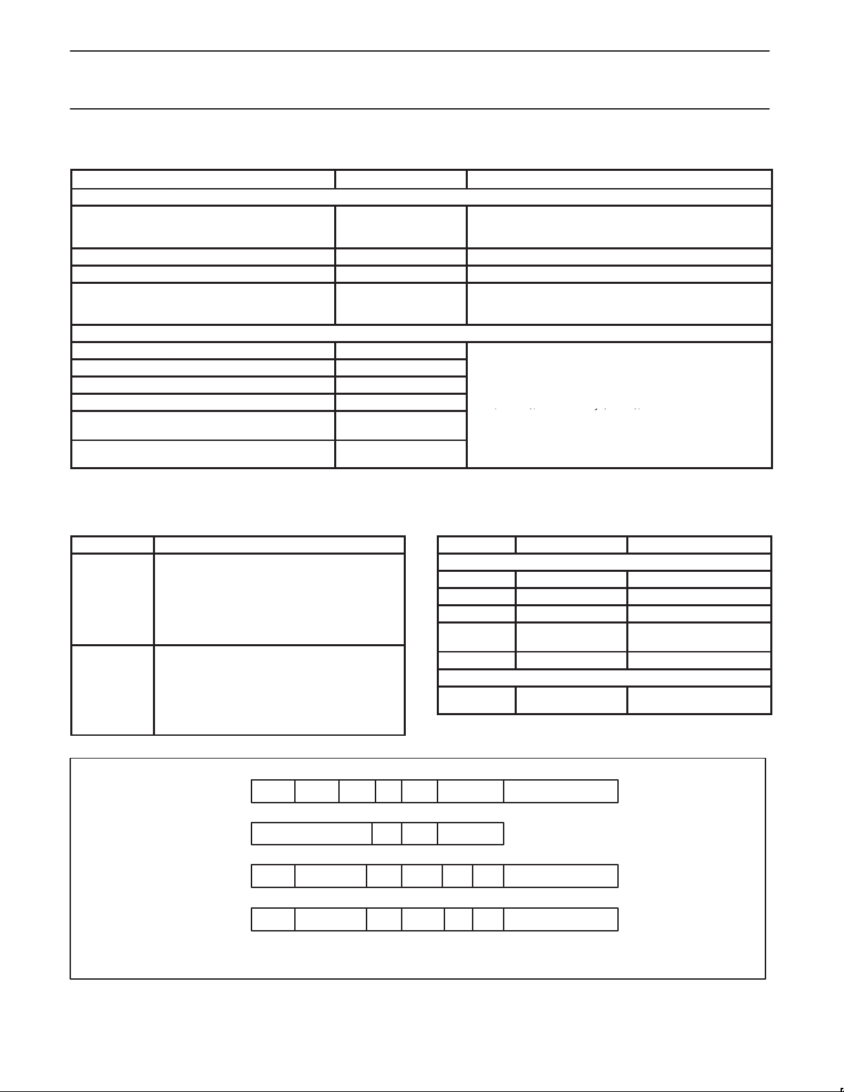
These registers are used for character assembly (CSSR
,), y(),
SCN2652/SCN68652Multi-protocol communications controller (MPCC)
Table 1. Register Access
REGISTERS NO. OF BITS DESCRIPTION*
Addressable
PCSAR
Parameter control sync/
address register
16
PCR Parameter control register 8 RDSRH contains receiver status information.
RDSR Receive data/status register 16 RDSRL = RxDB contains the received assembled character.
TDSR Transmit data/status register 16
Non-Addressable
CCSR Control character shift register 8
HSR Holding shift register 16
RxSR Receiver shift register 8
TxSR Transmitter shift register 8
RxCRC
TxCRC
Receiver CRC accumulation
register
Transmitter CRC generation
register
16
16
NOTES:
*H = High byte – bits 15–8
L = Low byte – bits 7–0
Table 2. Error Control
CHARACTER DESCRIPTION
FCS Frame check sequence is transmitted/received
BCC Block check character is transmitted/received as
as 16 bits following the last data character of a
BOP message. The divisor is usually
CRC–CCITT (X
16
+ X12 + X5 + 1) with dividend
preset to 1’s but can be other wise determined
by ECM. The inverted remainder is transmitter as
the FCS.
two successive characters following the last data
character of a BCP message. The polynomial is
CRC–16 (X
16
+ X15 + X2 + 1) or CRC–CCITT
with dividend preset to 0’s (as specified by
ECM). The true remainder is transmitted as the
BCC.
PCSARH and PCR contain parameters common to the
receiver and transmitter. PCSARL contains a programmable
SYNC character (BCP) or secondary station address (BOP).
TDSRH contains transmitter command and status
information. TDSRL = TxDB contains the character to be
transmitted
HSR, RxSR), disassembly (TxSR), and CRC
accumulation/generation (RxCRC, TxCRC).
Table 3. Special Characters
OPERATION BIT PATTERN FUNCTION
BOP
FLAG 01111110 Frame message
ABORT 11111111 generation Terminate communication
01111111 detection
GA 01111111
Address (PCSARL)
1
BCP
SYNC
(PCSARL) or
2
(TxDB)
generation
NOTES:
1. ( ) = contents of.
2. For IDLE = 0 or 1 respectively.
Terminate loop mode
repeater function
Secondary station address
Character synchronization
,
APAPCSAR
PCR
RDSR
TDSR
NOTE:
Refer to Register Formats for mnemonics and description.
1995 May 01
RERR
TERR15NOT DEFINED
15
PROTO14SS/GA13SAM12IDLE
15 14 13 12 11
TxCL
15
14 13
A B C
14 13
T
R
x
x
C
L
E
12
11
RAB/
ROR
GA
TGA12TABORT11TEOM
Figure 3. Short Form Register Bit Formats
11
10
98
E C M
10 9 8
C
10 9 8
10 9 8
RxCL
L
E
REOM
5
76543210
S/AR
RxDBRSOM
TxDBTSOM
SD00059
Page 6
Philips Semiconductors Product specification
SCN2652/SCN68652Multi-protocol communications controller (MPCC)
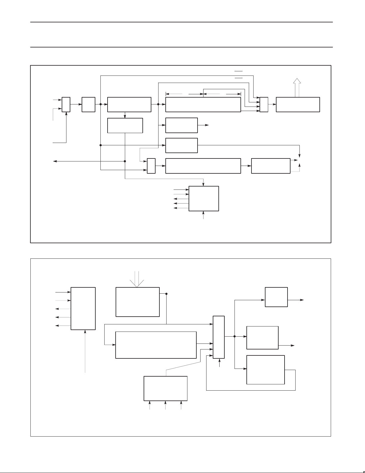
RxSI
XMITTER
MM
S/F
NOTES:
1. Detected in SYNC FF and 7 MS bits of CCSR.
2. In BOP mode, a minimum of two data characters must be received to turn the receiver active.
FROM
M
U
X
SEL
SYNC
FF
1-BIT
DELAY
CCSR (8)
SYNC/FLAG
COMPARATOR
BCP
PARITY (BCP)
RESET
RxE
RxA
RxDA
RxSA
ZERO (BOP)
DELETION
LOGIC
LOGIC
RxCRC ACC
1
BOP
M
U
X
Figure 4. MPCC Receiver Data Path
8 8
HSR (16)
ZERO
DELETION
CONTROL
CRC–16 (BCP) OR
CCRC–CCITT
(BOP)
RECEIVER
CONTROL
LOGIC
RxC
BCP . CRC
BOP . CRC
BCP . CRC
BOP
.
CRC
M
U
X
CRC–16 = 0
COMPARATOR
CRC–CCIT = F0B8
TO
RDSR
RxSR (8)
L
RERR
SD00060
FROM
OR PCSAR
TDSAR
L
RESET
TxE
TxA
TxBE
TxU
NOTES:
1. TxCRC selected if TEOM = 1 and the last data character has been shifted out of TxSR.
2. In BCP parity selected will be generated after each character is shifted out of TxSR.
TRANSMITTER
CONTROL
LOGIC
TxC
TXSR (8)
TXCRC ACC (16)
CRC–16 OR CRC–CCITT
FLAG ABORT GA
(SYNC)
L
CONTROL
CHARACTER
GENERATOR
Figure 5. MPCC Transmitter Data Path
SEL
SYNC
FF
1 BIT
DELAY
M
U
X
1, 2
BOP
ZERO
INSERTION
LOGIC
BCP
PARITY
GENERATION
TxSO
ZERO
INSERTION
CONTROL
SD00088
1995 May 01
6
Page 7

Philips Semiconductors Product specification
SCN2652/SCN68652Multi-protocol communications controller (MPCC)
FUNCTIONAL DESCRIPTION
The MPCC can be functionally partitioned into receiver logic,
transmitter logic, registers that can be read or loaded by the
processor, and data bus control circuitry. The register bit formats are
shown in Figure 3 while the receiver and transmitter data paths are
depicted in Figures 4 and 3.
RECEIVER OPERATION
General
After initializing the parameter control registers (PCSAR and PCR),
the RxE input must be set high to enable the receiver data path. The
serial data on the RxSI is synchronized and shifted into an 8-bit
Control Character Shift Register (CCSR) on the rising edge of RxC.
A comparison between CCSR contents and the FLAG (BOP) or
SYNC (BCP) character is made until a match is found. At that time,
the S/F output is asserted for one RxC time and the 16-bit Holding
Shift Register (HSR) is enabled. The receiver then operates as
described below.
BOP Operation
A flowchart of receiver operation in BOP mode appears in Figure 6.
Zero deletion (after five ones are received) is implemented on the
received serial data so that a data character will not be interpreted
as a FLAG, ABORT, or GA. Bits following the FLAG are shifted
through the CCSR, HSR, and into the Receiver Shift Register
(RxSR). A character will be assembled in the RxSR and transferred
to the RDSR
RxDA output will be asserted and the processor must take the
character no later than one RxC time after the next character is
assembled in the RxSR. If not, an overrun (RDSR11 = 1) will occur
and succeeding characters will be lost.
The first character following the FLAG is the secondary station
address. If the MPCC is a secondary station (PCSAR
contents of RxSR are compared with the address stored in
PCSAR
for the station; the RxA output is asserted, the character is loaded
into RDSR
(RSOM) is set. No match indicates that another station is being
addressed and the receiver searches for the next FLAG.
If the MPCC is a primary station, (PCSAR
address check is made; RxA is asserted and RSOM is set once the
first non-FLAG character has been loaded into RDSR
has been asserted. Extended address field can be supported by
software if PCSAR
When the 8 bits following the address character have been loaded
into RDSR
The processor should read this 8-bit character and interpret it as the
Control field.
Received serial data that follows is read and interpreted as the
information field by the processor. It will be assembled into character
lengths as specified by PCR
time a character has been transferred into RDSR
when RDSR
when RxSA is asserted. This occurs on a zero to one transition of
any bit in RDSR
except RSOM are cleared when RDSRH is read. The processor
for presentation to the processor. At that time the
L
= 1), the
12
. A match indicates the forthcoming message is intended
L
, RxDA is asserted and the Receive Start of Message bit
L
= 0), no secondary
12
and RxDA
L
= 0.
12
and RxDA has been asserted, RSOM will be cleared.
L
. As before, RxDA is asserted each
8–10
is read by the processor. RDSRH should only be read
L
except for RSOM. RxSA and all bits in RDSR
H
and is cleared
L
H
should check RDSR
set, then RDSR
12–15
each time RxSA is asserted. If RDSR9 is
9–15
should be examined.
Receiver character length may be changed dynamically in response
to RxDA: read the character in RxDB and write the new character
length into RxCL. The character length will be changed on the next
receiver character boundary . A received residual (short) character
will be transferred into RxDB after the previous character in RxDB
has been read, i.e. there will not be an overrun. In general the last
two characters are protected from overrun.
The CRC–CCITT, if specified by PCSAR
, is accumulated in
8–10
RxCRC on each character following the FLAG. When the closing
FLAG is detected in the CCSR, the received CRC is in the 16-bit
HSR. At that time, the Receive End of Message bit (REOM) will be
set; RxSA and RxDA will be asserted. The processor should read
the last data character in RDSR
RDSR
. If RDSR15 = 1, there has been a transmission error; the
9–15
accumulated CRC–CCITT is incorrect. If RDSR
and the receiver status in
L
≠ 0, last data
12–14
character is not of prescribed length. Neither the received CRC nor
closing FLAG are presented to the processor. The processor may
drop RxE or leave it active at the end of the received message.
RxBCP Operation
The operation of the receiver in BCP mode is shown in Figure 7.
The receiver initially searches for two successive SYNC characters,
of length specified by PCR
The next non-SYNC character or next SYNC character, if stripping is
not specified (PCSAR
13
enables the receiver data path. Once enabled, all characters are
assembled in RxSR and loaded into RDSR
character is available in RDSR
transition of any bit in RDSR
or RDSR
are read respectively.
H
If CRC–16 error control is specified by PCSAR
must determine the last character received prior to the CRC field.
When that character is loaded into RDSR
the received CRC will be in CCSR and HSR
transmission error, the processor must read the receiver status
(RDSR
) and examine RDSR15. This bit will be set for one
H
character time if an error free message has been received. If
RDSR
= 0, the CRC–16 is in error. The state of RDSR15 in BCP
15
CRC mode does not set RxSA. Note that this bit should be
examined only at the end of a message. The accumulated CRC will
include all characters starting with the first non-SYNC character if
PCSAR
PCSAR
= 1, or the character after the opening two SYNCs if
13
= 0. This necessitates external CRC generation/checking
13
when supporting IBM’s
BISYNC. This can be accomplished using the Philips
Semiconductors SCN2653 Polynomial Generator/Checker. See
Typical Applications.
If VRC has been selected for error control, parity (odd or even) is
regenerated on each character and checked when the parity bit is
received. A discrepancy causes RDSR
asserted. This must be sensed by the processor. The received parity
bit is stripped before the character is presented to the processor.
When the processor has read the last character of the message, it
should drop RxE which disables the receiver logic and initializes all
receiver registers and timing.
, that match the contents of PCSARL.
8–10
= 0), causes RxA to be asserted and
. RxDA is active when a
. RxSA is active on a 0 to 1
L
. The signals are cleared when RDSRl
H
L
, the processor
8–10
and RxDA is asserted,
L
. To check for a
L
to be set and RxSA to be
15
1995 May 01
7
Page 8

Philips Semiconductors Product specification
SCN2652/SCN68652Multi-protocol communications controller (MPCC)
PROCESSOR
FOR ONE RxC
BIT TIME
RxA = 1
RSOM = 1
FOR ONE
CHARACTER
TIME
RxE = 1
S/F = 1
START OF
MESSAGE
INITIALIZE PCSAR, PCR
RxE
= 1?
FLAG
IN CCSR*
?
FLAG
IN CCSR*
?
ASSEMBLE CHARACTER
IN RxSR. ZERO DELETION,
ACCUMULATE CRC IF
SPECIFIED
IS
NO
IT 1st
CHARACTER
AFTER FLAG
?
YES
SEC.
STATION
MODE
?
NO
(PCSAR
RxSR → RxDB
YES
YES
NO
(PCSAR
NO
NO
YES
SECONDARY
STATION
ADDRESS
YES
= 1)
12
= 0)
12
A
* TEST MADE
EVERY RxC TIME
(1) OVERRUN (ROVRN)
CAUSES LOSS OF
SUBSEQUENT
CHARACTERS
IS
CHARACTER
= PCSAR
L
?
YES
NO
RxDA = 1
(PROCESSOR
SHOULD
READ RxDB)
(PROCESSOR SHOULD
READ AND EXAMINE
RDSR
H
ROVRN, ABC, RERR)
S/F = 1 FOR ONE RxC
RXSA = 1
– REOM, RAB/GA,
BIT TIME
REOM = 1, RxA = 0
RECEIVER
STATUS BIT 0 → 1
EXCEPT RSOM
IN CCSR*
Figure 6. BOP Receive
TRANSMITTER OPERATION
General
After the parameter control registers (PCSAR and PCR) have been
initialized, TxSO is held at mark until TSOM (TDSR
is raised. Then, transmitter operation depends on protocol mode.
1995 May 01
) is set and TxE
8
?
YES
FLAG
?
YES – END OF MESSAGE
NO
NO
TxBOP Operation
Transmitter operation for BOP is shown in Figure 8. A FLAG is sent
after the processor sets the Transmit Start of Message bit (TSOM)
and raises TxE. The FLAG is used to synchronize the message that
follows. TxA will also be asserted. When TxBE is asserted by the
8
RxE → 0
?
YES
A
SD00061
NO
Page 9

Philips Semiconductors Product specification
SCN2652/SCN68652Multi-protocol communications controller (MPCC)
MPCC, the processor should load TDSR
the message. TSOM should be cleared at the same time TDSR
with the first character of
L
is
L
loaded (16-bit data bus) or immediately thereafter (8-bit data bus).
FLAGS are sent as long as TSOM = 1. For counting the number of
FLAGs, the processor should reassert TSOM in response to the
assertion of TxBE.All succeeding characters are loaded into TDSR
by the processor when TxBE = 1. Each
character is serialized in TxSR and transmitted on TxSO. Internal
zero insertion logic stuffs a “0” into the serial bit stream after five
successive “1s” are sent. This insures a data character will not
match a FLAG, ABORT, or GA reserved control character. As each
character is transmitted, the Frame Check Sequence (FCS) is
generated as specified by Error Control Mode (PCSAR
FCS should be the CRC–CCITT polynomial (X
16
+ X12 + X5 + 1)
8–10
). The
preset to 1s. If an underrun occurs (processor is not keeping up with
the transmitter), TxU and TERR (TDSR
) will be asserted with
15
ABORT or FLAG used as the TxSO line fill depending on the state
of IDLE (PCSAR
). The processor must set TSOM to reset the
11
underrun condition. To retransmit the message, the processor
should proceed with the normal start of message sequence.
A residual character of 1 to 7 bits may be transmitted at the end of
the information field. In response to TxBE, write the residual
character length into TxCL and load TxDB with the residual
character. Dynamic alteration of character length should be done in
exactly the same sequence. The character length will be changed
on the next transmit character boundary.
After the last data character has been loaded into TDSR
to TxSR (TxBE = 1), the processor should set TEOM (TDSR
and sent
L
). The
9
MPCC will finish transmitting the last character followed by the FCS
and the closing FLAG. The processor should clear TEOM and drop
TxE when the next TxBE is asserted. This corresponds to the start
of closing FLAG transmission. When TxE has been dropped. TxA
will be low 1 1/2 bit times after the last bit of the closing FLAG has
been transmitted. TxSO will be marked after the closing FLAG has
been transmitted.
If TxE and TEOM are high, the transmitter continues to send
FLAGs. The processor may initiate the next message by resetting
TEOM and setting TSOM, or by loading TDSR
with a data
L
character and then simply resetting TSOM (without setting TSOM).
TxBCP Operation
Transmitter operation for BCP mode is shown in Figure 9. TxA will
be asserted after TSOM = 1 and TxE is raised. At that time SYNC
characters are sent from PCSAR
as TSOM = 1. TxBE is asserted at the start of transmission of the
first SYNC character. For counting the number of SYNCs, the
processor should reassert TSOM in response to the assertion of
TxBE. When TSOM = 0 transmission is from TDSR
loaded with characters from the processor each time TxBE is
asserted. If this loading is delayed for more than one character time,
an underrun results: TxU and TERR are asserted and the
TxSO line fill depend on IDLE (PCSAR
TSOM and retransmit the message to recover. This is not
compatible with IBM’s BISYNC, so that the user must not underrun
when supporting that protocol.
or TDSRL (IDLE = 0 or 1) as long
L
, which must be
L
). The processor must set
11
CRC–16, if specified by PCSAR
character transmitted from TDSR
, is generated on each
8–10
when TSOM =0. The processor
L
must set TEOM = 1 after the last data character has been sent to
TxSR (TxBE = 1). The MPCC will finish transmitting the last data
character and the CRC–16 field before sending SYNC characters
L
which are transmitted as long as TEOM = 1. If SYNCs are not
desired after CRC–16 transmission, the processor should clear
TEOM and lower TxE when the TxBE corresponding to the start of
CRC–16 transmission is asserted. When TEOM = 0, the line is
marked and a new message may be initiated by setting TSOM and
raising TxE.
If VRC is specified, it is generated on each data character and the
data character length must not exceed 7 bits. For software LRC or
CRC, TEOM should be set only if SYNC’s are required at the end of
the message block.
SPECIAL CASE: The capability to transmit 16 spaces is provided
for line turnaround in half duplex mode or for a control recovery
situation. This is achieved by setting TSOM and TEOM, clearing
TEOM when TxBE = 1, and proceeding as required.
PROGRAMMING
Prior to initiating data transmission or reception, PCSAR and PCR
must be loaded with control information from the processor. The
contents of these registers (see Register Format section) will
configure the MPCC for the user’s specific data communication
environment. These registers should be loaded during power-on
initialization and after a reset operation. They can be changed at any
time that the respective transmitter or receiver is disabled.
The default value for all registers is zero. This corresponds to BOP,
primary station mode, 8-bit character length, FCS = CRC–CCITT
preset to 1s.
For BOP mode the character length register (PCR) may be set to
the desired values during system initialization. The address and
control fields will automatically be 8-bits. If a residual character is to
be transmitted, TxCL should be changed to the residual character
length prior to transmission of that character.
DATA BUS CONTROL
The processor must set up the MPCC register address (A2–A0),
chip enable (CE), byte select (BYTE), and read/write (R
before each data bus transfer operation.
During a read operation (R
/W = 0), the leading edge of DBEN will
initiate an MPCC read cycle. The addressed register will place its
contents on the data bus. If BYTE = 1, the 8-bit byte is placed on
DB15–08 or DB07–00 depending on the H/L status of the register
addressed. Unused bits in RDSR
are zero. If BYTE = 0, all 16 bits
L
(DB15–00) contain MPCC information. The trailing edge of DBEN
will reset RxDA and/or RxSA if RDSR
or RDSRH is addressed
L
respectively.
DBEN acts as the enable and strobe so that the MPCC will not
begin its internal read cycle until DBEN is asserted.
During a write operation (R
and/or DB
prior to the leading edge of DBEN. The stable data
07–00
/W = 1), data must be stable on DB
is strobed into the addressed register by DBEN. TxBE will be
cleared if the addressed register was TDSR
or TDSRL.
H
/W) inputs
15–08
1995 May 01
9
Page 10

Philips Semiconductors Product specification
SCN2652/SCN68652Multi-protocol communications controller (MPCC)
PROCESSOR
RxE = 1
S/F = 1 FOR ONE
RxC BIT TIME
RxA = 1
RxDA = 1
(PROCESSOR
SHOULD READ
RxDB)
INITIALIZE PCSAR, PCR
RxE
= 1?
YES
SYNC
1
DETECT
IN CCSR?
YES
SYNC
2
DETECT
IN CCSR?
YES
SYNC
DETECT IN
CCSR?
NO
ASSEMBLE CHARACTER
IN RxSR, STRIP VRC IF
SPECIFIED, ACCUMULATE
CRC IF SPECIFIED
RxSR → RxDB
NO
NO
NO
YES
A
STRIP
SYNC (PCSAR
= 1?
(1) SYNCs ARE ASSEMBLED
(2) OVERRUN (ROVRN) CAUSES
LOSS OF SUBSEQUENT
CHARACTERS
NO
YES
)
13
(PROCESSOR SHOULD
READ AND EXAMINE
NOTES:
1. Test made every RxC time.
2. Test made on Rx character boundary.
RxSA = 1
– ROVRN,
RDSR
H
RERR (IF VRC
SPECIFIED)
RxE = 0
WHEN LAST
CHARACTER HAS
BEEN SERVICED
ANY
RECEIVER
STATUS BIT
0 → 1
?
YES
RxE
= 0?
YES
A
NO
Figure 7. BCP Receive
NO
SD00062
1995 May 01
10
Page 11

Philips Semiconductors Product specification
SCN2652/SCN68652Multi-protocol communications controller (MPCC)
TSOM = 1
TxBE = 1
PROCESSOR
SHOULD LOAD
TxDB AND
TSOM = 0)
(PROCESSOR MAY
SET TABORT, TGA,
AS REQUIRED)
ON UNDERRUN:
TxU = 1, TERR = 1
(PROCESSOR
SHOULD
SET TSOM)
TxBE = 1
(PROCESSOR
SHOULD LOAD
TxDB WITH NEXT
DATA CHAR)
TxE = 1
TxA = 1
INITIALIZE PCSAR, PCR, TDSR
A
TxSO = MARK
B
TRANSMIT FLAG
SERIALIZE DATA CHARACTER
IN TxDB, ZERO INSERTION,
ACCUMULATE CRC IF
SPECIFIED BY ECM,
TRANSMIT ON TxSO
TSOM
TxE =
1?
ON TxSO
TSOM
= 0?
TABORT
= 1?
UNDER
RUN?
YES
YES
NO
NO
H
NO
NO
YES
YES
(PROCESSOR MUST CLEAR
TABORT/GA IN RESPONSE
TO TxBE = 1)
TxSO = ABORT = 11111111 IF IDLE = 0
FLAG = 01111110 IF IDLE = 1
TxSO = ABORT IF IDLE = 0
FLAG IF IDLE = 1
NO
TSOM
= 1?
B
YES
TxBE = 1
(PROCESSOR SHOULD
RESET TEOM AND SET
TSOM OR DROP TxE)
TxA = 0
*GA will be transmitted if TGA is set together with TEOM.
TEOM
= 1?
YES
TRANSMIT ACCUMULATED
FCS (IF SPECIFIED) AS
INVERTED REMAINDER
TRANSMIT FLAG ON TxSO*
TEOM
= 0?
YES
TSOM
= 1?
NO
TxE
NO
= 0?
YES
A
Figure 8. BOP Transmit
YES
NO
NO
B
SD00063
1995 May 01
11
Page 12

Philips Semiconductors Product specification
SCN2652/SCN68652Multi-protocol communications controller (MPCC)
PROCESSOR
TSOM = 1
TxE = 1
TxA = 1
TxBE = 1
AFTER SYNC(S), PROCESSOR
LOADS DATA CHARACTER
IN TxDB AND TSOM = 0
TxBE = 1
(PROCESSOR
SHOULD LOAD TxDB)
(PROCESSOR SHOULD
GET TEOM AT END OF
MESSAGE IF CRC
SPECIFIED)
TxU = 1, TERR = 1
(PROCESSOR SHOULD
SET TSOM = 1)
TxBE = 1
(PROCESSOR
SHOULD CLEAR
TEOM AND DROP
TxE)
INITIALIZE PCSAR, PCR, TDSR
TxSO = MARK
TSOM,
TxE
= 1?
YES
TRANSMIT SYNC ON TxSO
SYNC FROM PCSAR
SYNC FROM TxDB IDLE = 1
TSOM
= 0?
YES
SERIALIZE DATA CHARACTER
IN TxDB, GENERATE VRC
OR ACCUMULATE CRC AS
SPECIFIED, TRANSMIT ON TxSO
TEOM
= 1?
YES
TRANSMIT ACCUMULATED
CRC SPECIFIED (IF NO
CRC, TEOM SHOULD = 0)
TEOM
= 0?
C
YES
H
NO
– IDLE = 0
L
NO
NO
C
TxSO = SYNC FROM PCSARL IF IDLE = 0
NO
TxSO = SYNC OR TxDB DEPENDING ON
A
NO
UNDER-
RUN?
YES
MARK IF IDLE = 1
UNTIL TSOM = 1
B
IDLE BIT
B
1995 May 01
TxA = 0
TxE
= 0?
NO
YES
A
Figure 9. BCP Transmit
12
SD00064
Page 13

Philips Semiconductors Product specification
SCN2652/SCN68652Multi-protocol communications controller (MPCC)
Table 4. MPCC Register Addressing
A2 A1 A0 REGISTER
Byte = 0 (16-Bit Data Bus = DB15 – DB00)
0 0 X RDSR
0 1 X TDSR
1 0 X PCSAR
1 1 X PCR*
Byte = 1 (8-Bit Data Bus = DB
0 0 0 RDSR
0 0 1 RDSR
0 1 0 TDSR
0 1 1 TDSR
1 0 0 PCSAR
1 0 1 PCSAR
1 1 0 PCRL*
1 1 1 PCR
NOTES:
* PCR lower byte does not exist. It will be all “0”s when read.
** Corresponding high and low order pins must be tied together.
7–0
or DB
15–8
**)
L
H
L
H
L
H
H
Table 5. Parameter Control Register (PCR)–(R/W)
BIT NAME MODE FUNCTION
00–07 Not Defined
08–10 RxCL BOP/BCP Receiver character length is loaded by the processor when RxCLE = 0. The character length is
valid after transmission of single byte address and control fields have been received.
10 9 8
000 8
001 1
010 2
011 3
100 4
101 5
110 6
111 7
11 RxCLE BOP/BCP Receiver character length enable should be zero when the processor loads RxCL. The
remaining bits of PCR are not affected during loading. Always 0 when read.
12 TxCLE BOP/BCP Transmitter character length enable should be zero when the processor loads TxCL. The
remaining bits of PCR are not affected during loading. Always 0 when read.
13–15 TxCL BOP/BCP Transmitter character length is loaded by the processor when TxCLe = 0. Character bit length
specification format is identical to RxCL. It is valid after transmission of single byte address and
control fields.
Char length (bits)
1995 May 01
13
Page 14

Philips Semiconductors Product specification
SCN2652/SCN68652Multi-protocol communications controller (MPCC)
Table 6. Parameter Control SYNC/Address Register (PCSAR)–(R/W)
BIT NAME MODE FUNCTION
00–07 S/AR BOP SYNC/address register. Contains the secondary station address if the MPCC is a secondary
BCP SYNC character is loaded into this register by the processor. It is used for receive and
08–10 ECM BOP/BCP Error Control Mode 10 9 8 Suggested Mode Char. length
11 IDLE Determines line fill character to be used if transmitter underrun occurs (TxU asserted and
BOP IDLE = 0, transmit ABORT characters during underrun and when TABORT = 1.
BCP IDLE = 0 transmit initial SYNC characters and underrun line fill characters from theS/AR.
12 SAM BOP Secondary Address Mode = 1 if the MPCC is a secondary station. This facilitates automatic
13 SS/GA Strip SYNC/Go Ahead. Operation depends on mode.
BOP SS/GA = 1 is used for loop mode only and enables GA detection. When a GA is detected as a
BCP SS/GA = 1, causes the receiver to strip SYNC’s immediately following the first two SYNC’s
14 PROTO Determines MPCC Protocol mode
BOP PROTO = 0
BCP PROTO = 1
15 APA BOP All parties address. If this bit is set, the receiver data path is enabled by an address field of
station. The contents of this register is compared with the first received non-FLAG character
to determine if the message is meant for this station.
transmit bit synchronization with bit length specified by RxCL and TxCL.
CRC–CCITT preset to 1’s 0 0 0 BOP 1–8
CRC–CCITT preset to 0’s 0 0 1 BCP 8
Not used 0 1 0 –––
CRC–16 preset to 0’s 0 1 1 BCP 8
VRC odd 1 0 0 BCP 5–7
VRC even 1 0 1 BCP 5–7
Not used 1 1 0 –––
No error control 1 1 1 BCP/BOP 5–8
ECM should be loaded by the processor during initialization or when both data paths are idle.
TERR set) and transmission of special characters for BOP/BCP.
IDLE = 1, transmit FLAG characters during underrun and when TABOR T = 1.
IDLE = 1 transmit initial SYNC characters from TxDB and marks TxSO during underrun.
recognition of the received secondary station address. When transmitting, the processor must
load the secondary address into TxDB.
SAM = 0 inhibits the received secondary address comparison which serves to activate the
receiver after the first non-FLAG character has been received.
closing character, REOM and RAB/GA will be set and the processor should terminate the
repeater function. SS/GA = 0 is the normal mode which enables ABORT detection. It causes
the receiver to terminate the frame upon detection of an ABORT or FLAG.
detected. SYNC’s in the middle of a message will not be stripped. SS/GA = 0, presents any
SYNC’s after the initial two SYNC’s to the processor.
‘11111111’ as well as the normal secondary station address.
1995 May 01
14
Page 15

Philips Semiconductors Product specification
SCN2652/SCN68652Multi-protocol communications controller (MPCC)
Table 7. Transmit Data/Status Register (TDSR) (R/W except TDSR15)
BIT NAME MODE FUNCTION
00–07 TxDB BOP/BCP Transmit data buffer. Contains processor loaded characters to be serialized in TxSR and
08 TSOM Transmitter start of message. Set by the processor to initiate message transmission provided
BOP TSOM = 1 generates FLAGs. When TSOM = 0 transmission is from TxDB and FCS
BCP TSOM = 1 generates SYNCs from PCSARL or transmits from TxDB for IDLE = 0 or 1
09 TEOM Transmit end of message. Used to terminate a transmitted message.
BOP TEOM = 1 causes the FCS and the closing FLAG to be transmitted following the transmission
BCP TEOM = 1 causes CRC–16 to be transmitted (if selected) followed by SYNCs from PCSAR
10 TABORT BOP Transmitter abort = 1 will cause ABORT or FLAG to be sent (IDLE = 1 or 1) after the current
11 TGA BOP Transmit go ahead (GA) instead of FLAG when TEOM = 1. This facilitates repeater
12–14 Not Defined
15 TERR Read
only
BOP ABORT’s or FLAG’s are sent as fill characters (IDLE = 0 or 1)
BCP SYNC’s or MARK’s are sent as fill characters (IDLE = 0 or 1). For IDLE = 1 the last character
transmitted on TxSO.
TxE = 1.
generation (if specified) begins. FCS, as specified by PCSAR
preset to 1’s.
respectively. When TSOM = 0 transmission is from TxDB and CRC generation (if specified)
begins.
of the data character in TxSR. FLAGs are transmitted until TEOM = 0. ABORT or GA are
transmitted if T ABORT or TGA are set when TEOM = 1.
or TxDB (IDLE = 0 or 1). Clearing TEOM prior to the end of CRC–16 transmission (when
TxBE = 1) causes TxSO to be marked following the CRC–16. TxE must be dropped before a
new message can be initiated. If CRC is not selected, TEOM should not be set.
character is transmitted. (ABORT = 11111111)
termination in loop mode. (GA = 01111111)
Transmitter error = 1 indicates the TxDB has not been loaded in time (one character time–1/2
TxC period after TxBE is asserted) to maintain continuous transmission. TxU will be asserted
to inform the processor of this condition. TERR is cleared by setting TSOM. See timing
diagram.
before underrun is not valid.
, should be CRC–CCITT
8–10
L
1995 May 01
15
Page 16

Philips Semiconductors Product specification
PARAMETER
TEST CONDITIONS
UNIT
SCN2652/SCN68652Multi-protocol communications controller (MPCC)
Table 8. Receiver Data/Status Register (RDSR)–(Read Only)
BIT NAME MODE FUNCTION
00–07 RxDB BOP/BCP Receiver data buffer. Contains assembled characters from the RxSR. If VRC is specified, the
08 RSOM BOP Receiver start of message = 1 when a FLAG followed by a non-FLAG has been received and
09 REOM BOP Receiver end of message = 1 when the closing FLAG is detected and the last data character
10 RAB/GA BOP Received ABORT or GA character = 1 when the receiver senses an ABORT character if
11 ROR BOP/BCP Receiver overrun = 1 indicates the processor has not read last character in the RxDB within
12–14 ABC BOP Assembled bit count. Specifies the number of bits in the last received data character of a
15 RERR BOP/BCP Receiver error indicator should be examined by the processor when REOm = 1 in BOP, or
parity bit is stripped.
the latter character matches the secondary station if SAM = 1. RxA will be asserted when
RSOM = 1. RSOM resets itself after one character time and has no affect on RxSA.
is loaded into RxDB or when an ABORT/GA character is received. REOM is cleared on
reading RDSRH, reset operation, or dropping of RxE.
SS/GA = 0 or a GA character if SS/GA = 1. RAB/GA is cleared on reading RDSRH, reset
operation, or dropping of RxE. A received abort does not set RxDA.
one character time + 1/2 RxC period after RxDA is asserted. Subsequent characters will be
lost. ROR is cleared on reading RDSRH, reset operation, or dropping of RxE.
message and should be examined by the processor when REOM = 1(RxDA and RxSA
asserted). ABC = 0 indicates the message was terminated (by a flag or GA) on a character
boundary as specified by PCR
character. ABC is cleared when RDSR
residual character is right justified inRDSRL.
. Otherwise, ABC = number of bits in the last data
8–10
is read, reset operation, or dropping RxE. The
H
when the processor determines the last data character of the message in BCP with CRC or
when RxSA is set in BCP with VRC.
CRC–CCITT preset to 1’s/0’s as specified by PCSAR
RERR = 1 indicates FCS error (CRC ≠ F0B8 or ≠ 0)
8–10
:
RERR = 0 indicates FCS received correctly (CRC = F0B8 or = 0)
CRC–16 preset to 0’s on 8-bit characters specified by PSCAR
RERR = 1 indicates CRC–16 received correctly (CRC = 0).
8–10
:
RERR = 0 indicates CRC–16 error (CRC≠0)
VRC specified by PCSAR
RERR = 1 indicates VRC error
8–10
:
RERR = 0 indicates VRC is correct.
DC ELECTRICAL CHARACTERISTICS
1995 May 01
Input voltage
V
IL
V
IH
Low 0.8 V
High 2.0
Output voltage
V
OL
V
OH
I
CC
Low IOL = 1.6mA 0.4 V
High IOH = –100µA 2.4
Power supply current VCC = 5.25V, TA = 0°C 150 mA
Leakage current
I
IL
I
OL
Input VIN = 0 to 5.25V 10 µA
Output V
Capacitance
C
C
IN
OUT
Input VIN = 0V, f = 1MHz 20 pF
Output V
1, 2
LIMITS
Min Typ Max
= 0 to 5.25V 10
OUT
= 0V, f = 1MHz 20
OUT
16
Page 17

Philips Semiconductors Product specification
PARAMETER
UNIT
ns
SCN2652/SCN68652Multi-protocol communications controller (MPCC)
AC ELECTRICAL CHARACTERISTICS
1, 2, 3
2MHz CLOCK
Min Typ Max
Set-up and hold time
t
ACS
t
ACH
t
DS
t
DH
t
RXS
t
RxH
Address/control set-up 50
Address/control hold 0
Data bus set-up (write) 50 ns
Data bus hold (write) 0
Receiver serial data set-up 150
Receiver serial data hold 150
Pulse width
t
RES
t
DBEN
RESET 250 ns
DBEN 250 m
4
Delay Time
t
DD
t
TxD
t
DBEND
t
DF
Data bus (read) 170
Transmit serial data 250
DBEN to DBEN delay 200
Data bus float time (read) 150 ns
f Clock (RxC, TxC) frequency 2.0 MHz
t
CLK1
t
CLK2
t
CLK0
Clock high (MM = 0) 165
Clock high (MM = 1) 240 ns
Clock low 240
NOTES:
1. Parameters are valid over operating temperature range unless otherwise specified. See ordering code table for applicable temperature
range and operating supply range.
2. All voltage measurements are referenced to ground. All time measurements are at 0.8V or 2.0V. Input voltage levels for testing are 0.4V and
2.4V.
3. Output load C
4. m = TxC low and applies to writing to TDSR
= 100pF.
L
only.
H
TIMING DIAGRAMS
RESET
RESET RESET AND WRITE DATA BUS
t
RES
DBEN
A
A
,
0
CE, R/W,
BYTE
D
0–D15
(READ)
D0–D
15
(WRITE)
2
t
ACS
t
ACS
FLOATING VALID VALID FLOATING
t
DS
t
DD
t
NOT
Figure 10. Timing Diagrams
DBEN
t
ACH
t
ACH
t
DF
t
DH
SD00065
1995 May 01
17
Page 18

Philips Semiconductors Product specification
SCN2652/SCN68652Multi-protocol communications controller (MPCC)
TIMING DIAGRAMS (Continued)
CLOCK
1/f
TxC
TxC
TxSO
TxSO
RxC
RxSI
MARK
TxD
t
t
CLK1
CLK0
t
RxStRxH
t
t
CLK1
CLK0
Figure 11. T iming Diagrams (cont.)
TRANSMIT – START OF MESSAGE
1
8 TxC
SYNC/FLAG
1
SD00066
1ST CHAR
TxBE
DBEN
TxE
TxA
NOTES:
1. SYNC may be 5 to 8 bits and will contain parity bit as specified.
2. TxA goes high relative to TxC rising edge after TSOM has been set and TxE has been raised.
3. TxBE goes low relative to DBEN falling edge on the first write transfer into TDSR. It is reasserted 1 TxC time before the first bit of the transmitted SYNC/FLAG. TxBE then goes
low relative to DBEN falling edge when writing into TDSR
character, except in BOP mode when the CRC is to be sent as the next character (see Transmit Timing–End of Message).
3
SET TSOM LOAD 1st CHAR RESET TSOM LOAD 2nd CHAR
2
and/or TDSRL. It is reasserted on the rising edge of the TxC that corresponds to the transmission of the last bit of each
H
Figure 12. Timing Diagrams (cont.)
1995 May 01
18
SD00067
Page 19

Philips Semiconductors Product specification
SCN2652/SCN68652Multi-protocol communications controller (MPCC)
TIMING DIAGRAMS (Continued)
TRANSMIT – END OF BOP MESSAGE
TxC
TxSO
1
TxBE
LOAD LAST CHAR SET TEOM RESET TEOM
DBEN
2
TxE
3
TxA
NOTES:
1. TxBE goes low relative to the falling edge of DBEN corresponding to loading TDSR
dropped.
2. TxE can be dropped before resetting TEOM if TxBE (corresponding to the closing FLAG) is high. Alternatively TxE can remain high and a new message initiated.
3. TxA goes low after TxE has been dropped and 1 1/2 TxC’s after the last bit of the closing FLAG has been transmitted.
. It goes high one TxC before character transmission begins and also when TxA has been
H/L
FLAGCRCLAST CHARNEXT TO LAST CHAR
MARK
Figure 13. Timing Diagrams (cont.)
TRANSMIT TIMING – END OF BCP MESSAGE
TxC
SD00068
LAST CHARNEXT TO LAST CHAR
TxBE
LOAD LAST CHAR SET TEOM RESET TEOM
DBEN
TxE
TxA
NOTE:
1. When SCN2652 generated CRC is not required. TEOM should only be set if SYNCs are to follow the message block. In that case, TxE should be dropped in response to TxBE
(which corresponds to the start of transmission of the last character). When CRC is required, TxE must be dropped before CRC transmission is complete. Otherwise, the contents
of TxDB will be shifted out on TxSO. This facilitates transmission of contiguous messages.
CRC
1
MARKTxSO
Figure 14. Timing Diagrams (cont.)
1995 May 01
19
SD00069
Page 20

Philips Semiconductors Product specification
SCN2652/SCN68652Multi-protocol communications controller (MPCC)
TIMING DIAGRAMS (Continued)
TRANSMIT UNDERRUN
TxC
1
TxU
SET TSOM
2
DBEN
NOTES:
1. TxU goes active relative to TxC falling edge if TxBE has not been serviced after n-1/2 TxC times (where n = transmit character length). TxU is reset on the TxC falling edge following assertion of the TSOM command.
2. An underrun will occur at the next character boundary if TEOM is reset and the transmitter remains enabled, unless the TSOM command is asserted or a character is loaded into
the TxDB.
SD00070
Figure 15. Timing Diagrams (cont.)
RECEIVE – START OF MESSAGE
RxC
RxA
1st CHAR READY
TO BE READ
2
RxDA
DBEN
3
S/F
RxE
NOTES:
1. RxA goes high relative to falling edge of RxC when RxE is high and: a. A data character following two SYNC’s is in RxDB (BCP mode). b. Character following FLAG is in RxDB
(BOP primary station mode). c. Character following FLAG is in RxDB and character matches the secondary station address or all parties address (BOP secondary station mode).
2. RxDA goes high on RxC falling edge when a character in RxDB is ready to be read. It comes up before RxSA and goes low on the falling edge of DBEN when RxDB is read.
3. S/F goes high relative to rising edge of RxC anytime a SYNC (BCP) or FLAG (BOP) is detected.
1
2nd CHAR READY
TO BE READ
1st CHAR READ 2nd CHAR READ
SD00071
Figure 16. Timing Diagrams (cont.)
1995 May 01
20
Page 21

Philips Semiconductors Product specification
SCN2652/SCN68652Multi-protocol communications controller (MPCC)
TIMING DIAGRAMS (Continued)
RECEIVE END OF MESSAGE
RxC
RxDA
1
RxSA
READ
DBEN
(8-BIT)
S/F
2
RxE
3
RxA
NOTES:
1. At the end of a BOP message, RxSA goes high when FLAG detection (S/F 1) forces REOm to be set. Processor should read the last data character (RDSRL) and status (RDSRH)
which resets RxDA and RxSA respectively. For BCP end of message, RxSA may not be set and S/F = 0. The processor should read the last data character and status.
2. RxE must be dropped for BCP with non-contiguous messages. It may be left on at the end of a BOP message (see BOP Receive Operation).
3. RxA is reset relative to the falling edge of RxC after the closing FLAG of a BOP message (REOM = 1 and RxSA active.) or when RxE is dropped.
DATA
READ
STATUS
SD00072
Figure 17. Timing Diagrams (cont.)
TYPICAL APPLICATIONS
SCN2652 MPCC MICROPROCESSOR INTERFACE
RESET
RESET
CLOCK
TS BUFFER
DATA BUS
8-BIT
µP
Φ
ADDRESS CONTROL
A2–A0, R/W DBEN CE
“1”
STATUS
DB0–DB7
BYTE
MPCC
SCN2652
TxC
RxC
TxSO
RxSI
LR
LR
SYNCHRO-
NOUS
LD
LR
MODEM
RxE TxE
MODEM
CONTROL
LOGIC
NOTES:
1. Possible µP interrupt requests are: RxDA RxSA TxBE TxU
2. Other SCN2652 status signals and possible uses are S F line idle indicator, frame delimiter. RxA handshake on RxE, line turn around control. TxA handshake on TxE, line turn
around control.
3. Line drivers/receivers (LD/LR) convert EIA to TTL voltages and vice-versa.
4. RTS should be dropped after the CRC (BCP) or FLAG (BOP) has been transmitted. This forces CTS low and TxE low.
5. Corresponding high and low order bits of DB must be OR tied.
DCD CTS
RTS, CTS,
DTR, DSR,
DCD
SD00073
Figure 18. Typical Applications
1995 May 01
21
Page 22

Philips Semiconductors Product specification
SCN2652/SCN68652Multi-protocol communications controller (MPCC)
TYPICAL APPLICATIONS (Continued)
DMA/PROCESSOR INTERFACE
DATA BUS
WORD COUNT
ADDRESS PTR
R/W CONTROL
DMA
CONTROLLER
SCN2652
ADDRESS AND
CONTROL
ADDRESS
/W CONTROLS
R
For non-DMA operation TxBE and RxDA are set to the processor which then loads or reads data characters as required.
RDREQ
TO PROCESSOR
WRREQ
DB15–DB00
RxDA
TxBE
A2–A0
BYTE
R
/W
CE
DBEN
RxC TxC RxSI TxSO
MODEM OR DCE
RxA
RxSA
SCN2652
RESET
SYSTEM ADDRESS AND CONTROL BUS
RxE
TxA
TxE
TxU
S/F
MM
8 OR 16 BITS
DB15–DB00
PROCESSOR (P)
AND
SUPPORT LOGIC:
1. INITIALIZES
SCN2652
2. SETS/RESETS
TSOM, TEOM
3. RESPONDS
TO RxSA
ADDRESS, R
CONTROL
Figure 19. Typical Applications (cont.)
/W,
RxDA
TxBE
DATA BUS
R/W
MEMORY
ADDRESS,
/W
CE, R
SD00074
COMPUTER
OR
TERMINAL
BAUD
RATE
GENERATOR
TxC
MPCC
SCN2652
CHANNEL INTERFACE
BAUD
RATE
GENERATOR
RxC
TxSO
RxSI
LD
LR
LD
LR
LR
LD
LR
LD
TxC
RxSI
TxSO
No Modem – DC Baseband Transmission
Figure 20. Typical Applications (cont.)
MPCC
SCN2652
RxC
COMPUTER
OR
TERMINAL
SD00075
1995 May 01
22
Page 23

Philips Semiconductors Product specification
SCN2652/SCN68652Multi-protocol communications controller (MPCC)
SCN2652/SCN2653 INTERF ACE TYPICAL PROTOCOLS:
BISYNC, DDCMP, SDLC, HDLC
INTERRUPTS TxBE, TxU, RxDA, RxSA
DB7–DB0
CPU
MPCC
SCN2652
A2
A1
A0
R
/W
DBEN
CE
(OPEN DRAIN)
5V
Figure 21. Typical Applications (cont.)
INT
DB7–DB0
CE0
SCN2653
A1
R
/W
A0
CE1
TxD
RxD
TxC
RxC
PGC
SD00076
1995 May 01
23
Page 24

1998 May 01
853–0590B 06688
0590B 40-PIN (600 mils wide) CERAMIC DUAL IN-LINE (F) PACKAGE (WITH WINDOW (FA) PACKAGE)
Philips Semiconductors Product specification
24
– E –
PIN # 1
– D –
– T –
SEATING
PLANE
0.098 (2.49)
0.040 (1.02)
0.100 (2.54) BSC
0.070 (1.78)
0.050 (1.27)
0.023 (0.58)
0.015 (0.38)
2.087 (53.01)
2.038 (51.77)
0.010 (0.254)TED
SEE NOTE 6
0.098 (2.49)
0.040 (1.02)
0.598 (15.19)
0.571 (14.50)
0.225 (5.72) MAX.
0.165 (4.19)
0.125 (3.18)
NOTES:
1. Controlling dimension: Inches. Millimeters are
shown in parentheses.
2. Dimension and tolerancing per ANSI Y14. 5M-1982.
3. “T”, “D”, and “E” are reference datums on the body
and include allowance for glass overrun and meniscus
on the seal line, and lid to base mismatch.
4. These dimensions measured with the leads
constrained to be perpendicular to plane T.
5. Pin numbers start with Pin #1 and continue
counterclockwise to Pin #40 when viewed
from the top.
6. Denotes window location for EPROM products.
0.620 (15.75)
0.590 (14.99)
(NOTE 4)
0.175 (4.45)
0.145 (3.68)
0.055 (1.40)
0.020 (0.51)
0.015 (0.38)
0.010 (0.25)
BSC
0.600 (15.24)
(NOTE 4)
0.695 (17.65)
0.600 (15.24)
SCN2652/SCN68562Multi-protocol communications controller (MPCC)
Page 25

Philips Semiconductors Product specification
SCN2652/SCN68562Multi-protocol communications controller (MPCC)
DIP40: plastic dual in-line package; 40 leads (600 mil) SOT129-1
1998 May 01
25
Page 26

Philips Semiconductors Product specification
SCN2652/SCN68562Multi-protocol communications controller (MPCC)
PLCC44: plastic leaded chip carrier; 44 leads SOT187-2
1998 May 01
26
Page 27

Philips Semiconductors Product specification
SCN2652/SCN68562Multi-protocol communications controller (MPCC)
NOTES
1998 May 01
27
Page 28

Philips Semiconductors Product specification
SCN2652/SCN68562Multi-protocol communications controller (MPCC)
Data sheet status
Data sheet
status
Objective
specification
Preliminary
specification
Product
specification
Product
status
Development
Qualification
Production
Definition
This data sheet contains the design target or goal specifications for product development.
Specification may change in any manner without notice.
This data sheet contains preliminary data, and supplementary data will be published at a later date.
Philips Semiconductors reserves the right to make chages at any time without notice in order to
improve design and supply the best possible product.
This data sheet contains final specifications. Philips Semiconductors reserves the right to make
changes at any time without notice in order to improve design and supply the best possible product.
[1]
[1] Please consult the most recently issued datasheet before initiating or completing a design.
Definitions
Short-form specification — The data in a short-form specification is extracted from a full data sheet with the same type number and title. For
detailed information see the relevant data sheet or data handbook.
Limiting values definition — Limiting values given are in accordance with the Absolute Maximum Rating System (IEC 134). Stress above one
or more of the limiting values may cause permanent damage to the device. These are stress ratings only and operation of the device at these or
at any other conditions above those given in the Characteristics sections of the specification is not implied. Exposure to limiting values for extended
periods may affect device reliability.
Application information — Applications that are described herein for any of these products are for illustrative purposes only. Philips
Semiconductors make no representation or warranty that such applications will be suitable for the specified use without further testing or
modification.
Disclaimers
Life support — These products are not designed for use in life support appliances, devices or systems where malfunction of these products can
reasonably be expected to result in personal injury . Philips Semiconductors customers using or selling these products for use in such applications
do so at their own risk and agree to fully indemnify Philips Semiconductors for any damages resulting from such application.
Right to make changes — Philips Semiconductors reserves the right to make changes, without notice, in the products, including circuits, standard
cells, and/or software, described or contained herein in order to improve design and/or performance. Philips Semiconductors assumes no
responsibility or liability for the use of any of these products, conveys no license or title under any patent, copyright, or mask work right to these
products, and makes no representations or warranties that these products are free from patent, copyright, or mask work right infringement, unless
otherwise specified.
Philips Semiconductors
811 East Arques Avenue
P.O. Box 3409
Sunnyvale, California 94088–3409
Telephone 800-234-7381
Copyright Philips Electronics North America Corporation 1998
All rights reserved. Printed in U.S.A.
print code Date of release: 08-98
Document order number:
1998 May 01
28
 Loading...