

Page 1
Silan
Semiconductors
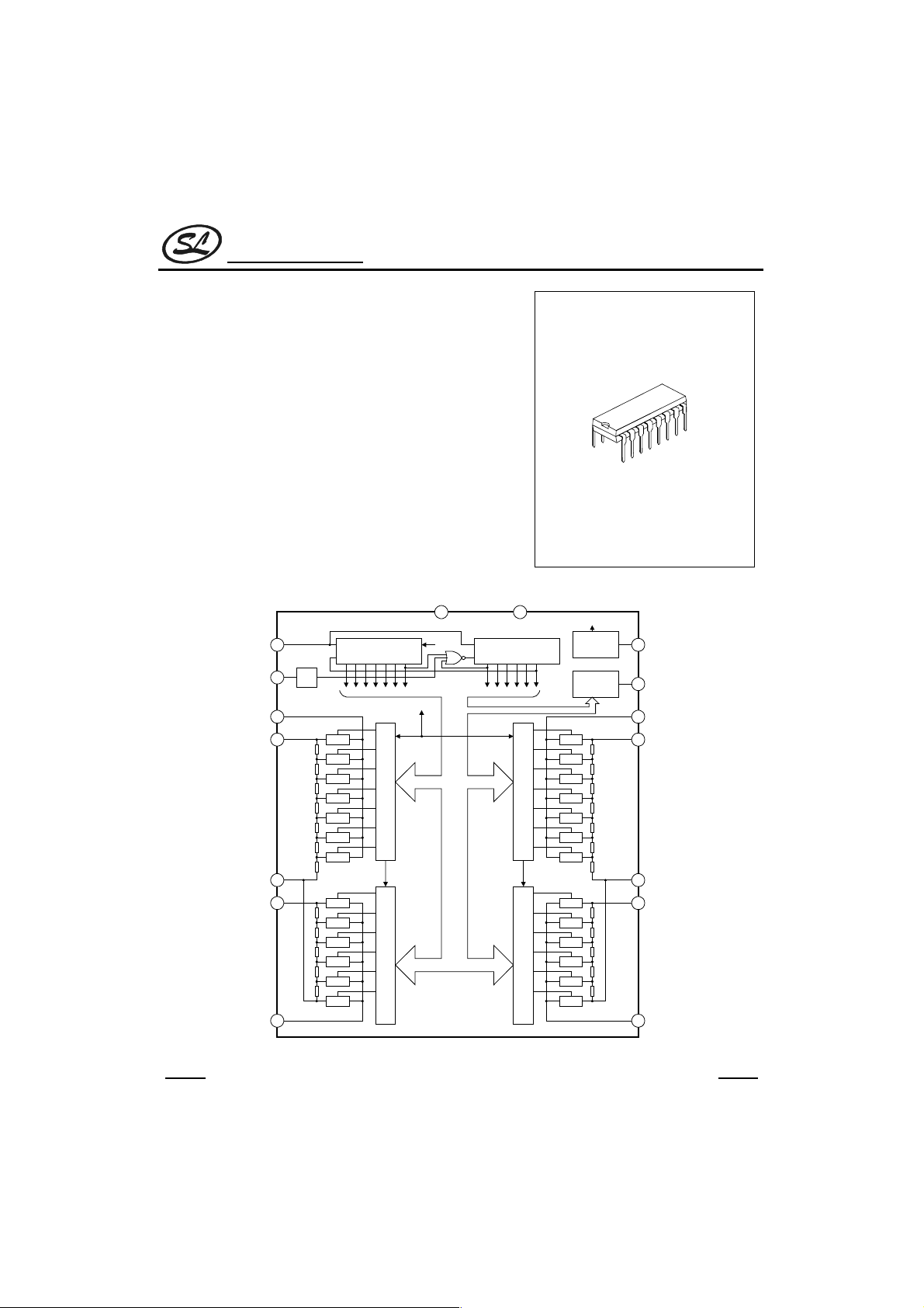
ELECTRONIC VOLUME CONTROLLER
DESCRIPTION
The SC9153A is CMOS IC which has been designed for
electronization volume control of audio equipment,etc.
FEATURES
*Wide operating voltage range(V
*Low current comsumption .
*Attenuation can be controlled from 0dB to –66dB by 2dB/step
*Both of dual power suppliers of (+) and (-) and a single power
supply can be used.
*Be capable of controlling attenuation by means of the built-in
oscillator and the up/down terminals.
6V ~ 12V)
DD=
BLOCK DIAGRAM
U/D
10
OSC
9
L-OUT1
2
L-IN1
3
A-GND
4
L-IN2
5
6
OSC
U/D
CK
A-SW
A-SW
A-SW
A-SW
A-SW
A-SW
A-SW
A-SW
A-SW
A-SW
A-SW
A-SW
A-SW
7 Bits Bidirectional
shift registor
VDD VSS
INT
U/D
6 Bits Bidirectional
CK
VDD
CK CK
7 Bits Latch Circuit
6BitsLatchCircuit
116
shift registor
7BitsLatchCircuit
CKCK
6 Bits Latch Circuit
INT
Auto Initialize
A-SW
A-SW
A-SW
A-SW
A-SW
A-SW
A-SW
A-SW
A-SW
A-SW
A-SW
A-SW
A-SW
SC9153A
INH
Circuit
Constant
Current
Circuit
7
DCO
8
R-OUT1
15
R-IN1
14
A-GND
13
R-IN2
12
R-OUT2L-OUT2
11
DIP-16
HANGZHOU SILAN MICROELECTRONICS JOINT-STOCK CO.,LTD
Rev: 1.0 2000.12.31
1
Page 2
Silan
Semiconductors
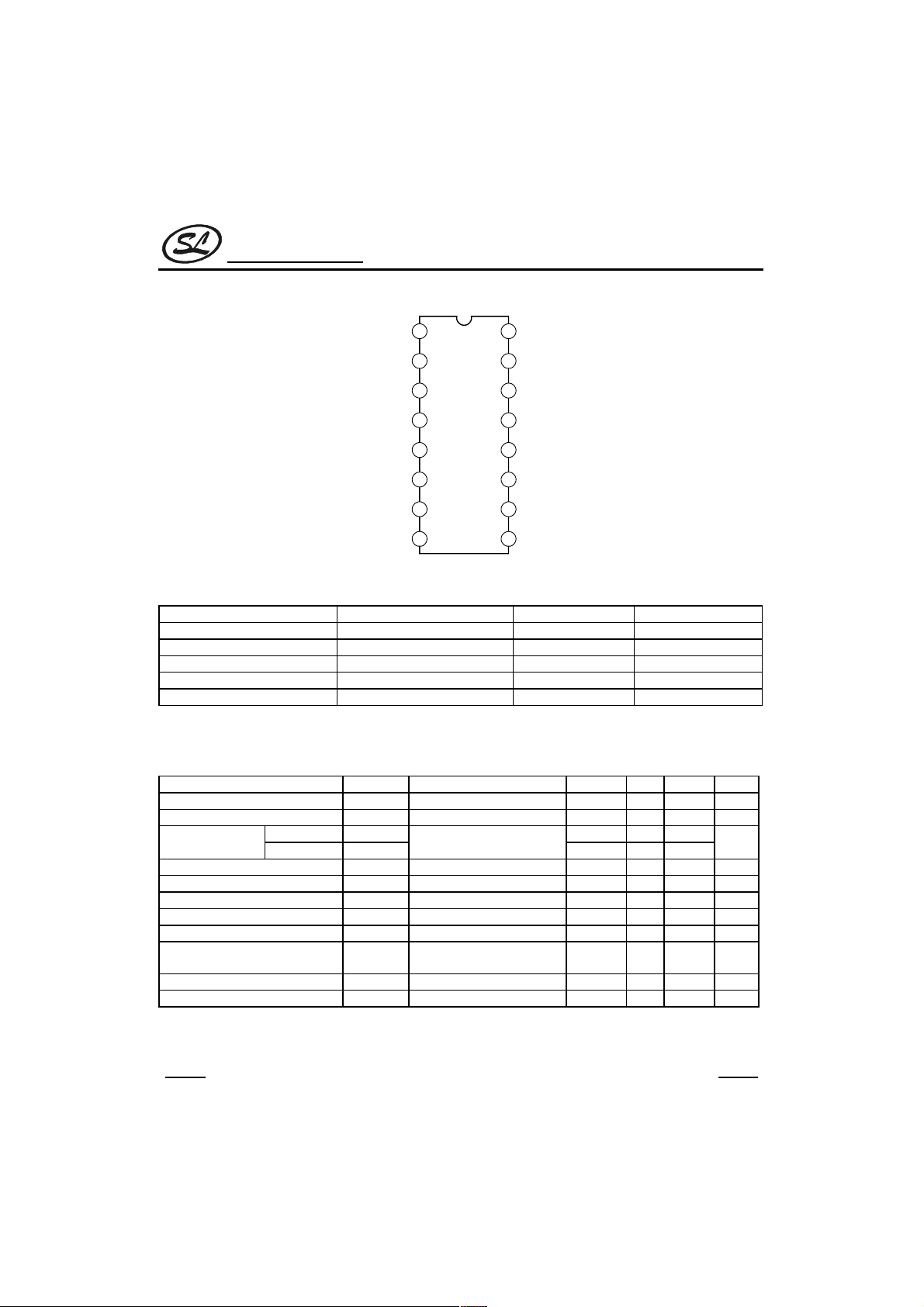
PIN CONFIGURATION
Vss
1
16
VDD
SC9153A
L-OUT1
L-IN1
A-GND
L-IN2
L-OUT2
INH
DCO
2
3
4
SC9153A
5
6
7
8
15
14
13
12
11
10
9
R-OUT1
R-IN1
A-GND
R-IN2
R-OUT2
U/D
OSC
ABSOLUTE MAXIMUM RATINGS
Characteristic Symbol Value Unit
Supply Voltage(Pin 16) V
Input/Output Voltage V
PowerDissipation P
DD
IN
D
Operating Temperature Topr -30 ~ +75
Storage Temperature Tstg -55 ~ +125
13.0 V
Vss-0.3V ~ VDD+0.3V V
150 mW
°C
°C
ELECTRICAL CHARACTERISTICS
(Tamb=25°C,VDD=12.0V, VSS=0V, Unless otherwise specified)
Parameter Symbol Test conditions Min Typ Max Unit
Operating Supply Voltage V
Operating supply current I
Input Voltage
“H” Level V
“L” Level V
Backup current I
Attenuator 1 (10dB/step) resistor R
Attenuator 2 (2dB/step) resistor R
DD
DD
IH
INH,U/D
IL
VDD=4V,INH=”L” 10
B
ATT-1R-IN1(L-IN1
ATT-2R-IN2(L-IN2
)~A-GND 25 50 70
)~A-GND 10 20 28
612V
13mA
0.8*V
DD
Vss-0.3 0.2*V
VDD+0.3
DD
V
µA
kΩ
kΩ
Attenuator Error 2dB
Maximum Input Amplitude Vin Biase VDD/2=6V 4.0 Vrms
Total Harmonic Distortion THD ATT=-10dB, fin=1kHz,
0.005 0.01 %
Vin=1.0Vp-p
DCO output current I
Oscillation frequency f
1 step 70 100 140
DCO
OSC
5 10k Hz
µA
HANGZHOU SILAN MICROELECTRONICS JOINT-STOCK CO.,LTD
Rev: 1.0 2000.12.31
2
Page 3
Silan
Semiconductors
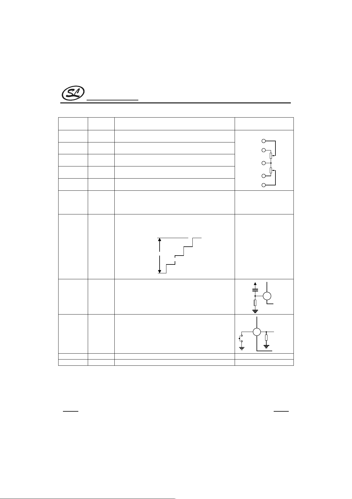
FUNCTIONAL DESCRIPTION OF EACH TERMINAL
Terminal
No.
2,15
3,14
4,13 A-GND
5,12
6,11
7 INH Inhibit terminal. When this terminal is at “L” level, all
8 DCO DC current output for displaying attenuation. Attenuation
Symbol Function Remarks
L-OUT1,
R-OUT1
L-IN1,
R-IN1
L-IN2,
R-IN2
L-OUT2,
R-OUT2
10dB/step attenuator outputs. A signal applied to IN is
attenuated in 7 steps from 0dB to 60dB at 10dB/step.
10dB/step attenuator inputs
Analog ground terminal
2dB/step attenuator inputs
2dB/step attenuator outputs. A signal applied to IN is
attenuated in 5 steps from 0dB to 8dB at 2dB/step.
input/output cut off and the SC9153A is placed in the
inhibit state. When at “H” level, the SC9153A operates
normally.
0dB~∞ is divided into 13 steps and approx 100µA/step is
transmitted.
0dB
1step=100µA
SC9153A
L and R are symmetrical.
Out1
IN1
A-
GND
IN2
Out2
Attenuation can be
converted to DC voltage
by attaching a resistor
between this terminal and
Vss.
13 steps
~
~
∞
9 OSC R,C connecting terminal or the oscillator. Up/down speed
10 U/D Attenuation terminal for oscillator. When this terminal is
1 VSS (-) Power supply terminal
16 VDD (+) Power supply terminal
of attenuation is decided by the attenuation up/down
control oscillator according to this time constant.
at “H” level, sound volume is increased synchronizing
with rise of the oscillator. Conversely, when this pin is at
“L” level, sound volume is decreased.
HANGZHOU SILAN MICROELECTRONICS JOINT-STOCK CO.,LTD
3
VDD
OSC
U/D
Rev: 1.0 2000.12.31
Page 4

Silan
Semiconductors
DESCRIPTION OF OPERATION
1. SETTING OF ATTENUATION
On the SC9153A, attenuation can be increased/decreased according to the stae of U/D terminal ”H” or “L”
level ) by actuating the build-in oscillator. The attenuation is automatically set at the -40dB positions when power is
applied.
Power
Supply
U/D
OSC
-30dB
-32dB
-34dB
-36dB
-38dB
-40dB
SC9153A
Vss
VDD
OSC
U/D
2.2µF
16
9
10
Rx=33kΩ
Cx=4.7µF
Rs=100kΩ
When the UP key is pressed after power ON,
the U/D terminal is place in the UP state at “H”
level, and the oscillator is actuated. When the
DOWN key is pressed, the U/D terminal is kept
at “L” level as long as the Down key is pressed,
and the oscillator is actuated in the down state
and therefore, attenuation is decreased.
Oscillation frequency is decided by Cx and Rx.
Fosc=1/(0.7*Rx*Cx) (Hz) (Rs>3Rx)
Cx Rs
Rx
UP Down
2.ATTENUATION DISPLAY OUTPUT
The SC9153A is provided with DC current output terminal for displaying attenuation. With 0dB ~ ∝ divided in to
13steps, current of approx 100µA/step is transmitted.
HANGZHOU SILAN MICROELECTRONICS JOINT-STOCK CO.,LTD
Rev: 1.0 2000.12.31
4
Page 5

Silan
Semiconductors
STEP DCO ATTENUATION REMARKS
00
I
1
2
3
4
5
6
7
8
9
10
11
12
13
DCO=100µA±30µA
2 × I
DCO
3 × I
DCO
4 × I
DCO
5 × I
DCO
6 × I
DCO
7 × I
DCO
8 × I
DCO
9 × I
DCO
10 × I
DCO
11 × I
DCO
12 × I
DCO
13 × I
DCO
-64dB ~ ∝
-60dB ~ -62dB
-54dB ~ -58dB
-50dB ~ -52dB
-44dB ~ -48dB
-40dB ~ -42dB
-34dB ~ -38dB
-30dB ~ -32dB
-24dB ~ -28dB
-20dB ~ -22dB
-14dB ~ -18dB
-10dB ~ -12dB
-4dB ~ -8dB
0dB ~ -2dB
8
Step 0
1kΩ
Vss
4
3
2
1 Step is about 100mV±30mV
1
3.ATTENUATOR
The attenuator unit consist of diffused resistors and analog switches. Attenuator-1 attenuates 0 ~ 60dB at
10dB/step while Attenuator-2 attenuates 2~8db at 2dB/step, a total of 0~ 66dB at 2dB/step.
Buffer
IN1
A-GND
R1
R1
R1
R1
R1
R1
R1
0
OUT1
-10
-20
-30
-40
-50
-60
Attenuator-1
R1=50kΩ(typical)
R2=20kΩ(typical)
IN2
R2
R2
R2
R2
R2
Attenuator-2
SC9153A
11
10
9
8
7
6
5
0
OUT2
-2
-4
-6
-8
-∞
13
12
About
1.3V
HANGZHOU SILAN MICROELECTRONICS JOINT-STOCK CO.,LTD
Rev: 1.0 2000.12.31
5
Page 6

Silan
Semiconductors
VDD
Vss
4.POWER SUPPLY
DUAL POWER SUPPLY
VDD
A-GND
VDD
IN1
Vss
U/D OSC
SC9153A
If there is possibility for excessive voltage being to the
attenuator, it is recommended to insert a protected diode as
illustrated below.
+VDD
UP DOWN
SC9153A
OSC
U/D
0
VSS
SINGLE POWER SUPPLY
VDD
A-GND
VSS
HANGZHOU SILAN MICROELECTRONICS JOINT-STOCK CO.,LTD
INH
VDD
U/D OSC
SC9153A
INH
VDD
DCO
DCO
DC
DC
6
UP DOWN
-VSS
+VDD
0
VSS (0V)
OSC
U/D
Rev: 1.0 2000.12.31
Page 7

Silan
Semiconductors
5.BACKUP WHEN POWER OFF
On the SC9153A, when the INH terminal is set
at “L” level, all input/output terminal are shut off
and current consumption is reduced to the
minimum. The backup by means of a capacitor
become possible in this condition. An example
of application, when a backup capacitor is
used, is shown right.
If V
DD-VSS drops below 4.0V, the backup
becomes impossible.
6.INITIALIZATION WHEN POWER ON
The SC9153A has the auto-initializating built-in
for initialization at time of power ON. As the
initializing system through detection of supply
voltage level is adopted., if rise power supply is
too fast, the initialization may not be fully
effected.(No external initialization is
necessary. )In addition for effective initialization,
it is necessary that the INH terminal is raised
simultaneously with supply voltage. Further, the
initializating level is –40dB.
It is recommended to rise supply voltage and the
INH terminal as illustrated below. If the VDD-VSS
drops below 4.0V, the auto-initializing function is
actuated.
+B
-VSS
V
DD-VSS
10KΩ
51KΩ
or INH
Terminal
Voltage
10KΩ
1000µF
T>1ms
SC9153A
16
VDD
7
INH
16V
1
VSS
VDD-VSS=4.0V
HANGZHOU SILAN MICROELECTRONICS JOINT-STOCK CO.,LTD
Rev: 1.0 2000.12.31
7
Page 8

Silan
Semiconductors
APPLICATION CIRCUIT (L-CH ONLY)
680Ω
10µF
VSS= -6V
Input
1µF
1µF
1
2
3
4
5
16
15
14
13
12
UTC4558
120kΩ
27pF
470kΩ1µF
82kΩ
1.2kΩ 0.022µF
1
2
3
4
5
2700pF
10µF
27kΩ
5.6kΩ
560kΩ
16 1
39kΩ
15
14
13
12
SC9153A
VDD= +6V
10µF
0.012µF
0.01µF
16
2
0.068µF
3
4.7kΩ
4
5
15
14
13
12
Output
1µF
6
7
11
10
6
7
SC9153A SC9153A
Down
8 9
2.2µF
8 9
UP
11
10
6
7
SC9153A
8
_
+
2.2µF
VOLUME TREBLE BASS
HANGZHOU SILAN MICROELECTRONICS JOINT-STOCK CO.,LTD
8
11
10
9
_
+
Rev: 1.0 2000.12.31
2.2µF
Page 9

Silan
Semiconductors
PACKAGE OUTLINE
DIP-16-300-2.54 UNIT:mm
2.54
SC9153A
0.25
6.40
1.50
19.4
3.51
0.46
7.62
15 degree
5.083.30
HANGZHOU SILAN MICROELECTRONICS JOINT-STOCK CO.,LTD
Rev: 1.0 2000.12.31
9
 Loading...