

Page 1

SAN3021
sames
sames
samessames
APPLICATION NOTE
SA2531/2 Single Chip Telephone:
Using dynamic microphone
as tone ringer
1 Scope
This Application Note describes how to modify the standard application AN1500A to use a dynamic microphone
instead of the standard electret microphone. Additionally, an application is shown, which uses the dynamic
microphone as tone ringer.
2 Key Features
•
Updating existing systems using dynamic handset microphone
•
No need for a piezo ringer when using the dynamic microphone as tone ringer
Table of Contents
1 SCOPE................................................................................................................................................................. 1
2 KEY FEATURES ................................................................................................................................................. 1
3 OTHER APPLICABLE DOCUMENTS AND PAPERS........................................................................................ 1
4 REVISION STATUS............................................................................................................................................. 1
5 GENERAL DESCRIPTION.................................................................................................................................. 2
6 HARDWARE CONFIGURATION......................................................................................................................... 2
6.1 U
6.1.1 Ringer part............................................................................................................................................. 2
6.1.2 Microphone amplifier part...................................................................................................................... 3
6.2 A
7 APPLICATION SCHEMATIC:............................................................................................................................. 4
8 LIABILITY AND COPYRIGHT STATEMENT...................................................................................................... 5
3 Other applicable documents and papers
Application Note AN1500A: SA2532K Single Chip Telephone Demo Board
4 Revision status
SING THE DYNAMIC MICROPHONE A S TONE RINGER (SCHEMATIC :A
MPLIFIER FOR GENERAL PURPOSE APPLICATIONS (SCHEMATIC :B
)................................................................. 2
)................................................................... 3
SAN3021 Application Note (this document)
SAN3021 Schematic Rev. 1.1
SAN3021 PDS038-SA2531/2-004 Rev. B 21-03-00
Page 2

SAN3021
5 General description
Dynamic handset microphones have been widely replaced by electret microphones, mainly because of higher
output level, low EMC sensitivity and price issues. Therefore, the standard Single Chip Telephone application,
AN1500 is based on using an electret handset microphone.
However, there are situations where usage of a dynamic microphone is still desired, e.g.
•
when updating an existing design , using a dynamic handset microphone
•
when taking advantage of the higher speech quality of dynamic microphones
•
when using the dynamic microphone as tone ringer
6 Hardware configuration
Generally, because of the lower output level of a dynamic micr ophone (≈10dB less than an electret microphone)
the microphone signal must be amplified by a simple 10dB amplifier before it can be fed into the microphone
inputs, M1 and M2 of the SA2531/2.
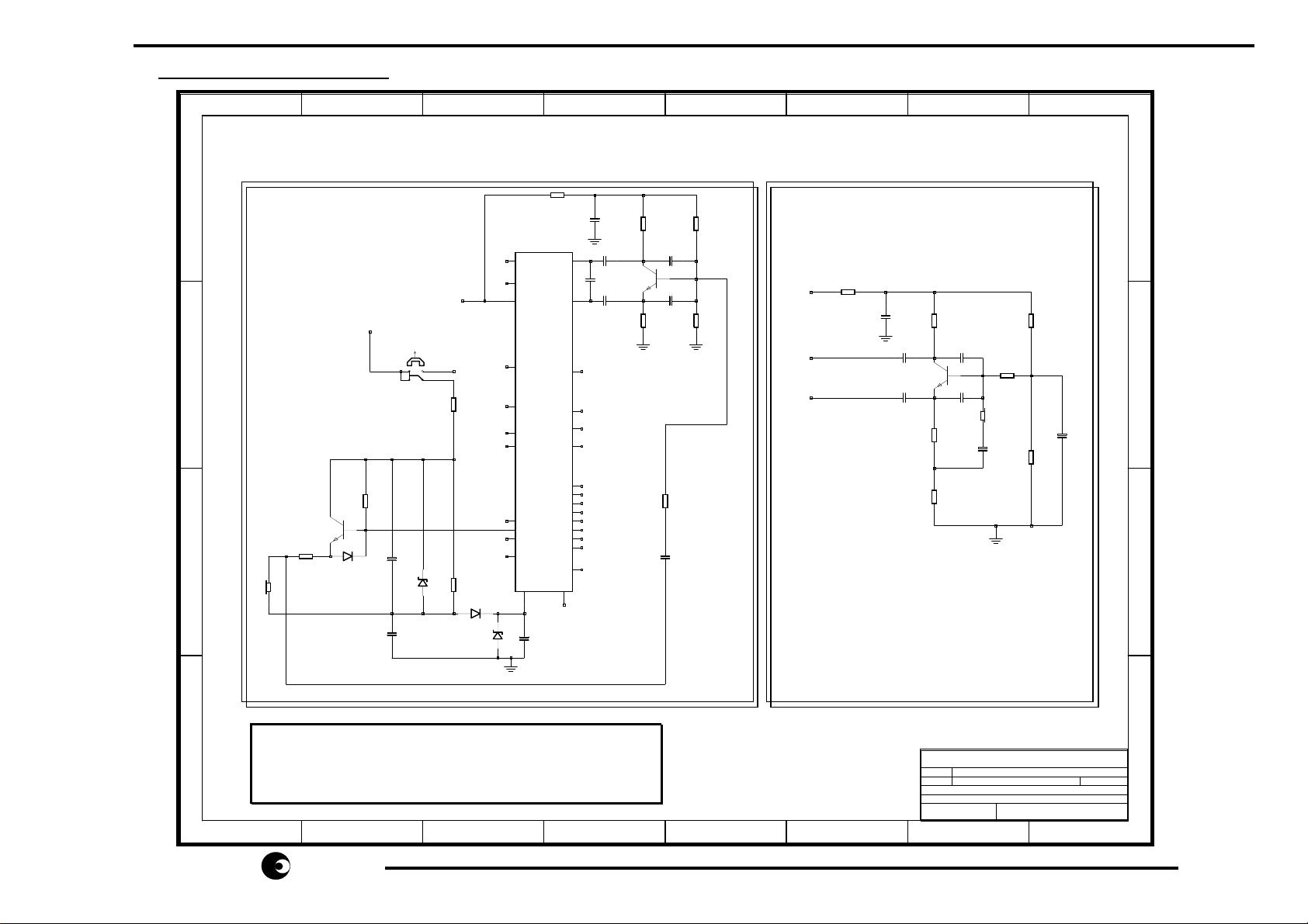
In the following schematic, two basic considerations when using dynamic microphones are shown:
1. A single ended circuit, which uses the dynamic microphone for both microphone and tone ringer.
2. A differential circuit, which is fully balanced, to replace an electret microphone.
6.1 Using the Dynamic Microphone as Tone Ringer (Schematic :A)
6.1.1 Ringer part
The piezo tone ringer used in AN1500 can be replaced by a dynamic m icrophone, when close attention is paid to
the following considerations :
Since a maximum sound pressure is required in ringing mode, the maximum DC current and AC level
for the type of dynamic microphone used must not be exceeded.
To limit the output of the ringer am plifier Q 4, the zener diode D4 should be reduced to 15V . R18 limits the output
current, it can also be used to set the ringer volume.
Since the microphone (= the ringer) is connected single ended to V
, any noise on VDD would be amplified by the
DD
microphone amplifier, causing higher noise for the transmitted signal. Therefore, D6 and C10 are added to
reference the micr ophone amplifier input to V
(over C10) but at the same tim e keep the DC level above VDD in
SS
ringing mode.
The ringer cannot be referenced to V
With the application s hown, the anode of D6 will be V
, because it would discharge VDD during ringing!
SS
+0.7V, because during ringing VDD is supplied over the
DD
ringing capacitor. (not shown).
2/5
sames
sames
samessames
Page 3

SAN3021
6.1.2 Microphone Amplifier
Q5 is a simple “classic” amplifier, which amplifies the single ended signal by ≈10dB. Gain can be adjusted by
varying R21. R23 is the feedback resistor to set a stable DC bias point. R24 and R25 are setting the base voltage.
The transistor type used (in this case BC549) should be a general purpose low noise transistor.
The single ended signal is decoupled by C17. R26 is required to limit the input current to the amplifier during
ringing.
C15 and C16 are EMC capacitors to limit the bandwidth of the amplifier. Frequencies >10kHz are being attenuated.
The amplifier is supplied by (the initial electret microphone supply) R20 and C14. C14 should be increased to
220µF. Since this supply is derived from the line output, there will be som e small r ipple from the transm itted signal
at C14.
In order not to form a positive f eedback
loop from LI over the m icrophone supply, Q5 and the internal m icrophone
amplifier (M1/M2 to LI) , care must be taken to connect M1/M2 inputs in the correct manner as shown in the
application.
With this connection, a negative feedback loop is formed, rejecting any ripple on C14.
Because of the unbalanced, single ended structure of this amplifier, its input is very sensitive. T herefore it
is recommended to use this application only in one-piece telephones with shortest possible wires
between microphone and amplifier !
6.2 Amplifier for General Purpose Applications (Schematic :B)
This amplifier is similar to the amplifier described in pt. 6.1, however the microphone is balanced (RR23B and
RR26 = 2kΩ).
Amplifier gain = RR21 / RR23B = 3:1 = 10dB.
This application can directly replace an electret microphone. Becaus e of the differential, balanced str ucture of the
amplifier input , it is also suitable for longer distances between microphone and amplifier, e.g. corded handsets.
3/5
sames
sames
samessames
Page 4
SAN3021
7 Application schematic:
1 2 3 4 5 6 7 8
Applications Using Dynamic Handset Microphone
A
A. Using dynamic handset
microphone as ringer
R20
2K2
+
C14
220u/25V
R21
6..10K
R24
360K
B. Amplifier for general
applications.
A
in one-piece telephones.
IC1
AGND
SA2531/2
C9
470u/16V
RO1
RO2
OSC
23
M1
C12
C11
100N
C13
BC549
100N
X
24
M2
2
3
5
12
16
C1
15
C2
14
C3
13
C4
20
R1
19
R2
18
R3
17
R4
11
VSS
264
1N
Q5
R23
2K
C17
10n
C16
C15
R26
1K1
1N
R25
110K
LI
M1
M2
27
2K2
+
RR20
CC14
100u/25V
23
24
CC11
CC13
100N
100N
BC549
RR21
3K
Q6
RR23A
1K
RR23B
2K
CC19
CC15
1N
1N
MIC
+
CC17
10U
1K1
RR26
RR24
27K
RR25
12K
B
+
CC18
10U
C
21
FCI
LS
1
27
LI
off
R17
100K
+
+
8
on
SW1_b
C8
10u/25V
C10
10u/16V
756
R7
220K
D4
R15
330K
15V
B
Q4
BC 547B
D5
C
MIC
R18
>=0
1N4148
D6
1N4148
D11
5V6
28
RI
6
STB
25
CS
7
CI RR
10
HS/DP
8
MO
22
MODE
9
LLC
VDD
+
4/5
The information furnished here by SAMES is believed to be correct and accurate. However, SAMES shall not
D
be held liable to any party for any damages including but not limited to personal injury, property damage, loss of
profits, loss of use, interuption of business or indirect, special, incidental or consequential damages, of any kind,
in connection with or arising out of the furnishing, performance or use of the technical data. No obligation or
liability to any third party shall arise or flow out of SAMES rendering technical or other services.
SAMES Telecom
Sch.
SAN3021
Pn#
Single Chip Telephone Application Circuit
Sh
01 01
3rd March 1997Date :of
Rev :
D
1.1
1 2 3 4 5 6 7 8
sames
sames
samessames
Page 5

SAN3021
8 Liability and Copyright Statement
Disclaimer:
Micro-Electronic Systems (Pty) Ltd ("SAMES”) and may not be copied or disclosed to a third party, in whole or in
part, without the express written consent of SAMES. T he information c ontained herein is current as of the date of
publication; however, delivery of this document shall not under any circum stances cr eate any implication that the
information contained herein is correct as of any time subsequent to such date. SAMES does not undertake to
inform any recipient of this docum ent of any changes in the information contained herein, and SAMES express ly
reserves the right to make changes in such information, without notification,even if such changes would render
information contained herein inaccurate or incomplete. SAMES makes no representation or warranty that any
circuit designed by reference to the inform ation contained her ein, will func tion without error s and as intended by the
designer
.
The information contained in this document is confidential and proprietary to South African
South African Micro-Electronic Systems (Pty) Ltd
P O Box 15888, 33 Eland Street,
Lynn East, Koedoespoort Industrial Area,
0039 Pretoria,
Republic of South Africa, Republic of South Africa
Tel: 012 333-6021 Tel: Int +27 12 333-6021
Fax: 012 333-3158 Fax: Int +27 12 333-3158
W eb Site : http://www.sames.c o.za
5/5
sames
sames
samessames
 Loading...