

Page 1

SAN3010
sames
sames
samessames
APPLICATION NOTE
SINGLE CHIP TELEPHONE INTERFACE FOR
KEYBOARD ENTRY VIA uC
1 Scope
This application note describes a simple interfac e for keyboard entry to the SA253x fam ily via a Microcontroller. It
also includes hardware description , flowchart and a software example based on the 80Cxx - family of
Microcontrollers.
2 Key Features
•
only 5 outputs and 1 input required from µC for handshake to access all keys in the SA253x keyboard matrix
•
universal interface, not restricted to specific Microcontrollers
•
supports both 3V- and 5V- µCs
•
same hardware for all single chip telephones : SA2531/2
•
same software for all single chip telephones, only key labels must be replaced
Table of Contents
1 SCOPE.............................................................................................................................................................................................................1
2 KEY FEATURES..............................................................................................................................................................................................1
3 OTHER APPLICABLE DOCUMENTS AND PAPERS......................................................................................................................................1
4 REVISION STATUS .........................................................................................................................................................................................2
5 GENERAL DESCRIPTION ...............................................................................................................................................................................2
6 HARDWARE CONFIGURATION......................................................................................................................................................................2
7 APPLICATION SCHEMATIC:...........................................................................................................................................................................2
8 SCANNING TABLE/FLOWCHART...................................................................................................................................................................3
9 SAMPLE SOFTWARE......................................................................................................................................................................................3
10 KEY ENTRY SIGNAL TABLE: .......................................................................................................................................................................4
11 APPENDIX A: APPLICATION SCHEMATIC ..................................................................................................................................................5
12 APPENDIX B: FLOWCHART:........................................................................................................................................................................6
13 APPENDIX C: SAMPLE SOFTWARE LISTING.............................................................................................................................................7
14 LIABILITY AND COPYRIGHT STATEMENT................................................................................................................................................13
3 Other applicable documents and papers
1. Data Sheet SA2531, SA2532
2. Pin-out Comparison SA2531/2
3. Product Presentation
4. Single Chip Telephone Evolution (Apr. 16, 1996)
SAN3010 PDS038-SA2531/2-003 Rev. B 21-03-00
Page 2

SAN3010
4 Revision status
SAN3010 Application Note (this document):
AN3010 Schematic: Rev.: A02
AN3010 Sample Software Rev.: A01
5 General Description
The interface m ust be capable of forcing the keyboard rows (hereafter indicated as R1...R4) both low (Vss) and
high (V
is forced at the sam e time while the remaining rows/columns m ust be high ohmic (her eafter indicated as Hi Z).
Since only one row/column must be driven at the same tim e, a decoder (IC5 = 74138) was implem ented to save
pin count of the µC. 3 output ports were used for row/colum n selection, 1 output port to disable all rows/columns
and 1 output port for the 3-state buffer inputs to select forcing high or low .
One µC pin must be configured as input for handshake.
If 9 output + 1 input pins are available from the µC (8 row/column selectors, 1 force hi/lo selector , 1 handshake
input) , IC5 = 74138 can be omitted.
IC3 & 4 (=74HC125) are separately addressable 3-state buffers.
A simple discrete NOR gate (Q1,D2,D3,R9..11) is used for synchronization.
) and forcing the keyboard columns (hereafter indicated as C1...C4) to high (VDD). Only one row or column
DD
6 Hardware configuration
The SA253x Single Chip Telephone can be connected to a µC for key entry when the following conditions are met:
Supply voltage: The SA253x works at 4V V
, its high/low input levels are 30/70% VDD.
DD
If the µC is supplied with >4V a current limiter (serial resistor) must be added to the row/column pins of the
SA253x.
If the µC supply is <4V it must provide adequate high level (> 70%V
of SA253x = >2.8V)
DD
Row driver : 4 Tristate output pins, each separ ately adjustable as either output (H i/Lo) or tris tate . Only one row is
driven at the same time, all other rows/columns are high ohmic.
Column driver: Tris tate output pins, each s eparately adjustable as either output (H i) or tris tate. Only one colum n is
driven at the same time, all other rows/columns are high ohmic.
Synchronization: The SA253x is intentionally designed for low standby power, so no oscillator is running as long as
no key is pressed. All the external row/column driving is done asynchronously. The scanning sequence is
synchronized by triggering a rising edge on specific columns (see table 1).
Therefore a 1-bit input must be provided for the synchronization.
7 Application schematic:
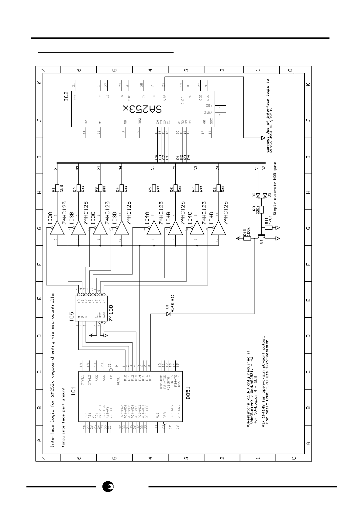
See also: Appendix A:
One solution which only requires 5 output pins and 1 input pin is shown in the attached schem atic. A comm on µC
(80C51-family) is used. This controller is widely known, so both hardware and software description in this
application note should be easily understood which simplifies adaption to any other controller.
The rows/columns are driven by 8 separately selectable tristate buffers (e.g. 74HC125). Power supply is 5V,
therefore resistors R2...R8 are necessary to provide adaption to the 4V-logic of the SA253x.
R1 is always connected by a 5kOhms resistor to prevent c ollis ion of two outputs when it initiates the key entry in an
unsynchronous state.
2/13
same s
same s
same ssame s
Page 3

SAN3010
Since only one row/column is forced high or low at the sam e tim e the num ber of µC output port pins c an be lim ited
by using a 1-of-8 decoder (74HC138). The 3 bits (A,B,C, respectively Port1 pins 0..2) select the appropriate
row/column, Port 1.4 disables all outputs.
The selected row/column is forced high or low depending on the state of Port1.5 .
Port 1.7 is used as input to detect the acknowledge of the SA253x during the sc anning phase. Acknowledge is
done by the rising edge of either C1,C2,C3 or C4.
The detection logic can be simplified by just monitoring C1 and C2, because one of both can always be used for
detection (see table 1, ColY).
Diode D1 is necessary to prevent collision of two outputs when Port1 is in output mode. Since Port1 of the 80C31 is
an open-drain output a diode can be used. For other controllers, using standard I/O , a resistor must be used in
place of the diode.
8 Scanning table/flowchart
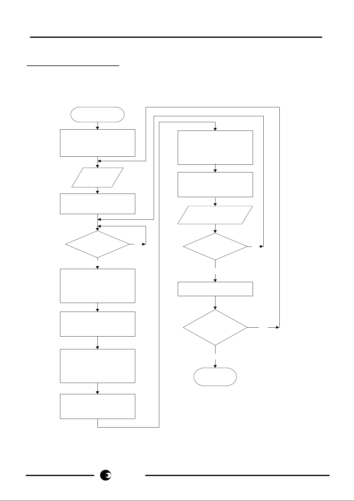
See also: Appendix B:
The interfacing procedure is shown in the attached flowchart, additional information is given below:
1) Key entry can only occur, when the SA253x has been off-hook for >20ms.
2) Internal key scanning of the SA253x is started when any Row (in our case: R1) has been forced low, then the
acknowledge by the SA253x is done by moving specific col-pins high.
3) When this Lo/Hi transition is detected by the µC the asynchronous timing must be started.
4) SCAN1 and SCAN 2 are the time slots at which a certain row must be forced high (SCAN1) and f orced low
(SCAN 2 ) , at time slot SCAN3 a certain column must be forced high. The key entry corresponding Row and
Column is shown in table 1. Between the SCAN1..3 time slots all rows and columns must be high ohmic (see
flowchart).
5) a valid key entry is accepted, when the SCAN1..3 procedure has been repeated 9 times.
6) a certain constant delay must be added between key entries. The only exception is, when memory keys are
cascaded. In this special cas e, entering a subsequent memory key is only accepted, when the previous m emory
has been fully dialed out.
9 Sample software
See also: Appendix C:
Attached is a sample software program, written in 8051 Assem bler language which incorporates all the nec essary
timing and correct row/column selection. The only entry is to load the accumulator with a key code and then make a
subroutine call.
See Table 1 for appropriate key codes when using either SA2531-2
The assembler command lines are well described, so it should be easily understood.
Again, adaption to other controllers based upon this software should be no problem.
Care must be taken when using a different system clock speed. In this case the delay blocks must be recalculated
based on the number of machine cycles used.
3/13
same s
same s
same ssame s
Page 4
SAN3010
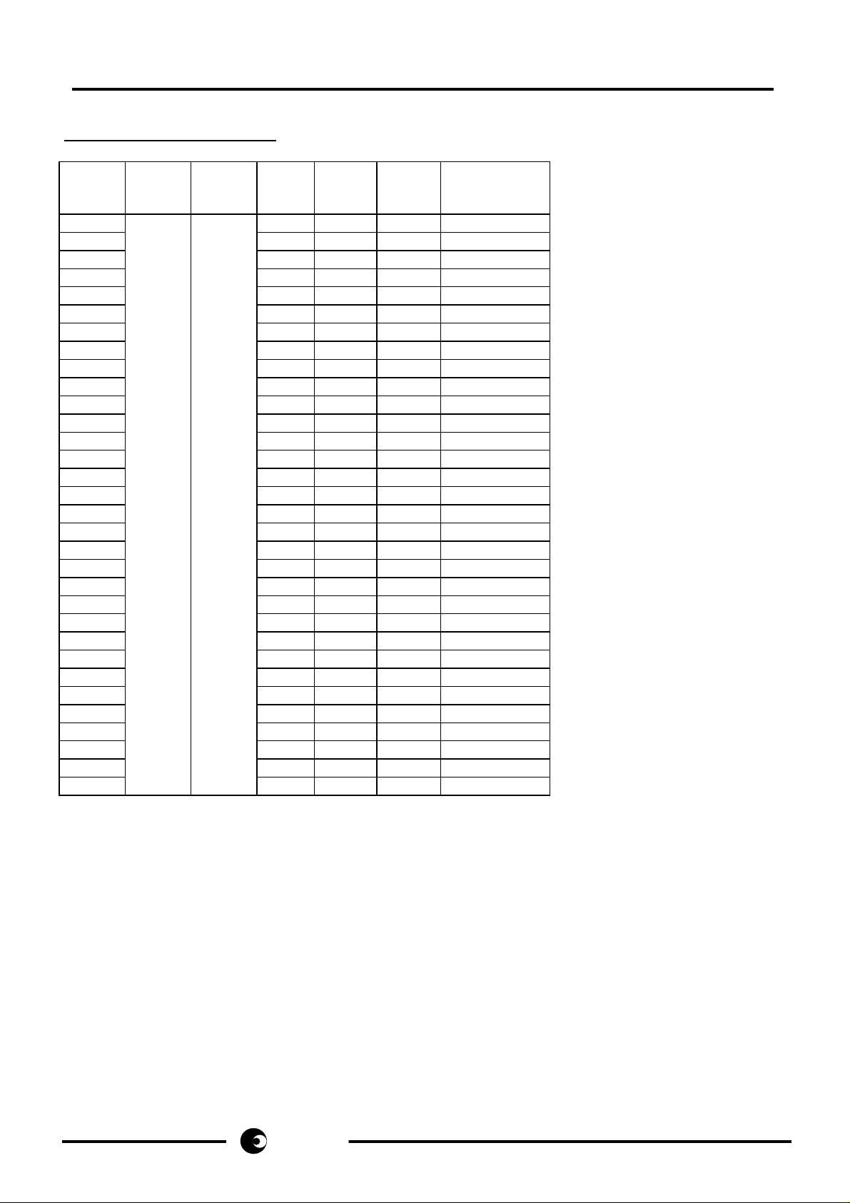
10 Key entry signal table:
Keycode
in S/W
example
0
1
2
3
4
5
6
7
8
9
10
11
12
13
14
15
16
17
18
19
20
21
22
23
24
25
26
27
28
29
30
31
Key - ID.
SA2531
Key - ID.
SA2532
SCAN 1
Row X
force Hi
SCAN 2
Row X
force Lo
SCAN 3
Col X
force Hi
Synchronization
on Col Y:
Mute Mute R1 R1 C1 C2,3,4
1 1 R1 R1 C2 C1,3,4
2 2 R1 R1 C3 C1,2,4
3 3 R1 R1 C4 C1,2,3
4 4 R2 R2 C1 C2,3,4
5 5 R2 R2 C2 C1,3,4
6 6 R2 R2 C3 C1,2,4
7 7 R2 R2 C4 C1,2,3
8 8 R3 R3 C1 C2,3,4
9 9 R3 R3 C2 C1,3,4
0 0 R3 R3 C3 C1,2,4
* * R3 R3 C4 C1,2,3
# # R4 R4 C1 C2,3,4
Pause Pause R4 R4 C2 C1,3,4
R R R4 R4 C3 C1,2,4
R2 R2 R4 R4 C4 C1,2,3
LNR LNR none R1 C1 C2,3,4
VOL none R1 C2 C1,3,4
VOL + none R1 C3 C1,2,4
VOL - none R1 C4 C1,2,3
Enter none R2 C1 C2,3,4
M5 none R2 C2 C1,3,4
M6 none R2 C3 C1,2,4
M7 none R2 C4 C1,2,3
M8 none R3 C1 C2,3,4
M9 none R3 C2 C1,3,4
M10 none R3 C3 C1,2,4
M1 none R3 C4 C1,2,3
M2 none R4 C1 C2,3,4
M3 none R4 C2 C1,3,4
M4 none R4 C3 C1,2,4
Mem none R4 C4 C1,2,3
4/13
same s
same s
same ssame s
Table 1: key entry lookup table
Page 5
SAN3010
11 Appendix A: Application Schematic
5/13
same s
same s
same ssame s
Page 6
SAN3010
12 Appendix B: Flowchart:
Flowchart for Microcontroller interface to AS253x single-chip-telephone
Notes: RowX,ColX,ColY: see table1
1 tclk= 256/3.58MHz = 71.5µs
all timings: Tol.:+-30µs
Start
delay5
wait >20ms after AS253x
off-hook to ensure correct
start-up
Key_in
Loop=0
Row1 force low
all other rows/cols=Hi Z
sync
Col Y=high ?
delay1
wait 1 tclk=71.5µs
and force RowX high
all other rows/cols= Hi Z
Yes
=SCAN1
delay2
wait 1.5 tclk=107.25µs
and disable all rows/cols=
Hi Z
No
wait 4.5 tclk= 321µs
and force ColX high
all other rows/cols= Hi Z
=SCAN3
delay6
wait 1.5 tclk=107.25µs
and disable all rows/cols=
Hi Z
Loop= Loop+1
Loop = 9 ?
Yes
delay7
wait 24*9 tclk=15.5ms
another key entry?
No
Yes
6/13
delay3
wait 4.5 tclk=321µs
and force RowY low
all other rows/cols= Hi Z
=SCAN2
delay4
wait 4.5 tclk=321µs
and disable all rows/cols=
Hi Z
same s
same s
same ssame s
No
end
Page 7

SAN3010
13 Appendix C: Sample Software listing
MCS-51 MACRO ASSEMBLER KEY
09/09/96 PAGE 1
LOC OBJ LINE SOURCE
1 ; (c) Austria Mikro Systeme International AG AMS
2 ; J.Janisch / telecom applications
3 ; Program name: KEY.ASM
4 ; Version: A01
5 ; Date: 1996-09-09
6 ; Author: J.Janisch / Telecom Applications
7 ;
8 ; User program for 8051 interface to SA253x for key entry via
9 ; microcontroller
10 ; Application Note AN3010
11 ; Program code is at Address 4000 HEX
12 ;
13 ; Reference for calculations:
14 ; Clock Frequency of Microcontroller (80C31) = 11.0592 MHz
15 ; --> 1 machine cycle = 12 clock cycles = 1.085 us
16 ;
17 ; Decoder Logic:
18 ; Port1:
19 ; P1.7 : active low input; detects rising edge of C1 OR C2
20 ; should be set high by any output command to port 1
21 ; P1.6 : not used
22 ; P1.5 : not used
23 ; P1.4 : forces selected row/column high or low
24 ; P1.3 : when high, disables all rows/columns (high Z)
25 ; P1.2 : row / column selector MSB
26 ; P1.1 : row / column selector
27 ; P1.0 : row / column selector LSB
28 ;
29 ; P1.2 P1.1 P1.0 select:
30 ; 0 0 0 row 1
31 ; 0 0 1 row 2
32 ; 0 1 0 row 3
33 ; 0 1 1 row 4
34 ; 1 0 0 column 1
35 ; 1 0 1 column 2
36 ; 1 1 0 column 3
37 ; 1 1 1 column 4
38 ;
39
40
0000 41 Row1 equ 0
0001 42 Row2 equ 1
0002 43 Row3 equ 2
0003 44 Row4 equ 3
0004 45 Col1 equ 4
0005 46 Col2 equ 5
0006 47 Col3 equ 6
0007 48 Col4 equ 7
0090 49 ForceHi equ 90H
0080 50 ForceLo equ 80H
7/13
same s
same s
same ssame s
Page 8

SAN3010
PAGE 2
LOC OBJ LINE SOURCE
0088 51 Disable equ 88H
52
53 ; #############################################################
54 ; Main program: load Accumulator with key code (see below) and
55 ; call subroutine "Key_In"
56
4000 57 Org 04000H ; set start address of program
4000 758160 58 mov SP,#060H ; set stack pointer
4003 00 59 HS_OK: NOP ; make sure that at this point
60 ; the SA253x has been off-hook
61 ; for >20ms
4004 740A 62 Ld_Key: mov a,#10 ; load keycode, here key "0"
4006 12400B 63 Call Key_in ; execute keystroke
4009 80FE 64 jmp $ ; end of main program, exit at
65 ; this point or continue with
66 ; next key entry
67 ; rem.: add additional delay when
68 ; cascading memories (s. Delay7:)
69 ; #############################################################
70 ; *************************************************************
71 ; Subroutine Key_in
72 ; *************************************************************
73 ; this subroutine executes a key entry to the SA253x
74 ; the corresponding key code(0...31) must be loaded in the accu
75 ; see table at label:"scantbl" for key codes
76 ; affected Registers:
77 ; A,B,R1,R2,R3,R5,R6,R7,DPTR
78
79
80
400B 12405C 81 Key_in: call getScTb ; preload Reg5..7 with scan table
82 ; Row X: variable in Reg5
83 ; Row Y: variable in Reg6
84 ; Col X: variable in Reg7
85
400E 7B00 86 Exe_Key:mov R3,#0 ; clear loop counter
4010 7480 87 mov a,#ForceLO ; force R1 low
4012 F590 88 mov P1,A
4014 3097FD 89 sync: jnb P1.7, $ ; make sure, C1= C2 = low
4017 2097FD 90 jb P1.7, $ ; wait for rising edge C1 or C2
91 ; = trigger for asynch. timing
92
93 ;- Delay 1:wait 71.5 us = 66 machine cycles and force RowX high
401A 791F 94 delay1: mov R1,#31 ; 1 cycle
401C D9FE 95 djnz R1,$ ; 2 cycles; #Loops=(66-4)/2 =31
96
401E 7490 97 SCAN1: mov A,#ForceHi ; 1 cycle
4020 4D 98 orl A,R5 ; 1 cycle
4021 F590 99 mov P1,A ; 1 cycle
100
101 ;------------------------------------------------------------- 102 ;Delay2:wait 107.25us= 99 machine cycles +disable all rows/cols
4023 7930 103 delay2: mov R1,#48 ; 1 cycle
4025 D9FE 104 djnz R1,$ ; 2 cycles; #Loops =(99-3)/2 = 48
4027 7488 105 mov A,#Disable ; 1 cycle
8/13
same s
same s
same ssame s
Page 9

SAN3010
PAGE 3
LOC OBJ LINE SOURCE
4029 F590 106 mov P1,A ; 1 cycle
107
108 ;------------------------------------------------------------- 109 ;-- Delay 3:wait 321 us = 295 machine cycles and force RowY low
402B 7991 110 delay3: mov R1,#145 ; 1 cycle
402D D9FE 111 djnz R1,$ ; 2 cycles;#Loops=(295-5)/2=145
112
402F 00 113 SCAN2: NOP ; 1 cycle
4030 7480 114 mov A,#ForceLO ; 1 cycle
4032 4E 115 orl A,R6 ; 1 cycle
4033 F590 116 mov P1,A ; 1 cycle
117
118 ;------------------------------------------------------------- 119 ;Delay 4: wait 321us= 295 machine cycles +disable all rows/cols
4035 7992 120 delay4: mov R1,#146 ; 1 cycle
4037 D9FE 121 djnz R1,$ ; 2 cycles;#Loops=(295-3)/2=146
4039 7488 122 mov A,#Disable ; 1 cycle
403B F590 123 mov P1,A ; 1 cycle
124
125 ;------------------------------------------------------------- 126 ;--- Delay 5:wait 321 us = 295 machine cycles + force ColX high
403D 7991 127 delay5: mov R1,#145 ; 1 cycle
403F D9FE 128 djnz R1,$ ; 2 cycles;#Loops=(295-5)/2=145
129
4041 00 130 SCAN3: NOP ; 1 cycle
4042 7490 131 mov A,#ForceHi ; 1 cycle
4044 4F 132 orl A,R7 ; 1 cycle
4045 F590 133 mov P1,A ; 1 cycle
134 ;------------------------------------------------------------- 135 ;Delay 6:wait 107.25us=99 machine cycles +disable all rows/cols
4047 7930 136 delay6: mov R1,#48 ; 1 cycle
4049 D9FE 137 djnz R1,$ ; 2 cycles;#Loops=(99-3)/2 = 48
404B 7488 138 mov A,#Disable ; 1 cycle
404D F590 139 mov P1,A ; 1 cycle
140
141 ;-------------------------------------------------------------404F 0B 142 inc R3 ; increment loop counter
4050 BB09C1 143 cjne R3,#9,Sync ; repeat loop 9 times
144
145
146 ;----- Delay 7: wait >15444 us = 14233 machine cycles before
147 ;----- next key entry
148 ;----- Remark: when cascading memory keys (M1...M10, Mem)
149 ;----- dialling of a subsequent stored number is only accepted
150 ;----- when the previous number has been fully dialled out.
151 ;----- Example1: key entry is "M1","M2"
152 ;----- M2 is only detected when M1 has completed dialing
153 ;----- its stored number, a delay has to be added between
154 ;----- key entries
155 ;----- Example2: key entry is "M1","0"
156 ;---- numbers are stored in FIFO ,so they can be entered
157 ;----- immediately after a Memory entry, no additional
158 ;----- delay necessary
4053 7900 159 delay7: mov R1,#0 ;
4055 7A1C 160 mov R2,#28
9/13
same s
same s
same ssame s
Page 10

SAN3010
PAGE 4
LOC OBJ LINE SOURCE
4057 D9FE 161 Del7a: djnz R1,$ ; =256*2 machine cycles
4059 DAFC 162 djnz R2,Del7a ; =2 machine cycles
163 ; 28*(256*2+2)=14392mc's=15.6ms
164
405B 22 165 ret ; return from subroutine
166
167
168 ;**************************************************************
169 ; Subroutine GetScTb
170 ;**************************************************************
171 ; this subroutine loads the Reg5..Reg7 registers according to
172 ; the keycode passed by the accumulator contents.
173 ; valid keycodes are 0.....31 (dec) = 0....1F (Hex)
174
175
405C 904074 176 GetScTb:mov dptr,#Scantbl ; calculate offset Address:
405F 75F003 177 mov B,#3 ; scantable startaddress
4062 A4 178 mul AB ; + (keycode *3)
4063 F5F0 179 mov B,A ; save offset address
180
4065 93 181 movc A,@A+DPTR ; get scan table: Row X
4066 FD 182 mov R5,A ; RowX
183
4067 E5F0 184 mov A,B
4069 04 185 inc A ; get next code
406A F5F0 186 mov B,A ; save
406C 93 187 movc A,@A+DPTR ; get scan table: Row X
406D FE 188 mov R6,A ; RowY
189
406E E5F0 190 mov A,B
4070 04 191 inc A ; get next code
4071 93 192 movc A,@A+DPTR ; get scan table: Row X
4072 FF 193 mov R7,A ; ColX
194
4073 22 195 ret
196
197 ; Scan table: the three constants indicate the rows/columns
198 ; to be driven in the SCAN1....SCAN3 phase
199 ;
4074 00 200 Scantbl:db Row1,Row1,Col1 ; key "Pgm/Mt, keycode= 0
4075 00
4076 04
4077 00 201 db Row1,Row1,Col2 ; key "1" , keycode= 1
4078 00
4079 05
407A 00 202 db Row1,Row1,Col3 ; key "2" , keycode= 2
407B 00
407C 06
407D 00 203 db Row1,Row1,Col4 ; key "3" , keycode= 3
407E 00
407F 07
4080 01 204 db Row2,Row2,Col1 ; key "4" , keycode= 4
4081 01
4082 04
4083 01 205 db Row2,Row2,Col2 ; key "5" , keycode= 5
10/13
same s
same s
same ssame s
Page 11

SAN3010
PAGE 5
LOC OBJ LINE SOURCE
4084 01
4085 05
4086 01 206 db Row2,Row2,Col3 ; key "6" , keycode= 6
4087 01
4088 06
4089 01 207 db Row2,Row2,Col4 ; key "7" , keycode= 7
408A 01
408B 07
408C 02 208 db Row3,Row3,Col1 ; key "8" , keycode= 8
408D 02
408E 04
408F 02 209 db Row3,Row3,Col2 ; key "9" , keycode= 9
4090 02
4091 05
4092 02 210 db Row3,Row3,Col3 ; key "0" , keycode= 10
4093 02
4094 06
4095 02 211 db Row3,Row3,Col4 ; key "*" , keycode= 11
4096 02
4097 07
4098 03 212 db Row4,Row4,Col1 ; key "#" , keycode= 12
4099 03
409A 04
409B 03 213 db Row4,Row4,Col2 ; key "PS,R1", keycode= 13
409C 03
409D 05
409E 03 214 db Row4,Row4,Col3 ; key "R,R2" , keycode= 14
409F 03
40A0 06
40A1 03 215 db Row4,Row4,Col4 ; key "R2,R3 , keycode= 15
40A2 03
40A3 07
40A4 88 216 db disable,Row1,Col1 ; key "LNR" , keycode= 16
40A5 00
40A6 04
40A7 88 217 db disable,Row1,Col2 ; key "Vol" , keycode= 17
40A8 00
40A9 05
40AA 88 218 db disable,Row1,Col3 ; key "Vol+" , keycode= 18
40AB 00
40AC 06
40AD 88 219 db disable,Row1,Col4 ; key "Vol-" , keycode= 19
40AE 00
40AF 07
40B0 88 220 db disable,Row2,Col1 ; keycode= 20
40B1 01
40B2 04
40B3 88 221 db disable,Row2,Col2 ; keycode= 21
40B4 01
40B5 05
40B6 88 222 db disable,Row2,Col3 ; keycode= 22
40B7 01
40B8 06
40B9 88 223 db disable,Row2,Col4 ; keycode= 23
40BA 01
11/13
same s
same s
same ssame s
Page 12

SAN3010
PAGE 6
LOC OBJ LINE SOURCE
40BB 07
40BC 88 224 db disable,Row3,Col1 ; keycode= 24
40BD 02
40BE 04
40BF 88 225 db disable,Row3,Col2 ; keycode= 25
40C0 02
40C1 05
40C2 88 226 db disable,Row3,Col3 ; keycode= 26
40C3 02
40C4 06
40C5 88 227 db disable,Row3,Col4 ; keycode= 27
40C6 02
40C7 07
40C8 88 228 db disable,Row4,Col1 ; keycode= 28
40C9 03
40CA 04
40CB 88 229 db disable,Row4,Col2 ; keycode= 29
40CC 03
40CD 05
40CE 88 230 db disable,Row4,Col3 ; keycode= 30
40CF 03
40D0 06
40D1 88 231 db disable,Row4,Col4 ; keycode= 31
40D2 03
40D3 07
232
233
234 end
REGISTER BANK(S) USED: 0
ASSEMBLY COMPLETE, NO ERRORS FOUND
12/13
same s
same s
same ssame s
Page 13

SAN3010
14 Liability and Copyright Statement
Disclaimer:
Micro-Electronic Systems (Pty) Ltd ("SAMES”) and may not be copied or disclosed to a third party, in whole or in
part, without the express written consent of SAMES. T he information c ontained herein is current as of the date of
publication; however, delivery of this document shall not under any circum stances cr eate any implication that the
information contained herein is correct as of any time subsequent to such date. SAMES does not undertake to
inform any recipient of this docum ent of any changes in the information contained herein, and SAMES express ly
reserves the right to make changes in such inform ation, without notification,even if such changes would render
information contained herein inaccurate or incomplete. SAMES makes no representation or warranty that any
circuit designed by reference to the inform ation contained her ein, will func tion without error s and as intended by the
designer
.
The information contained in this document is confidential and proprietary to South African
South African Micro-Electronic Systems (Pty) Ltd
P O Box 15888, 33 Eland Street,
Lynn East, Koedoespoort Industrial Area,
0039 Pretoria,
Republic of South Africa, Republic of South Africa
Tel: 012 333-6021 Tel: Int +27 12 333- 6021
Fax: 012 333-3158 Fax: Int +27 12 333-3158
W eb Site : http://www.sames.co.za
13/13
sames
sames
samessames
 Loading...