

Page 1

DATA SH EET
Preliminary specification
Supersedes data of 1995 Jun 15
File under Integrated Circuits, IC02
1996 Jul 08
INTEGRATED CIRCUITS
SAA7185
Digital Video Encoder (DENC2)
Page 2
1996 Jul 08 2
Philips Semiconductors Preliminary specification
Digital Video Encoder (DENC2) SAA7185
FEATURES
• CMOS 5 V device
• Digital PAL/NTSC encoder
• System pixel frequency 13.5 MHz
• Accepts MPEG decoded data
• 8-bit wide MPEG port
• Input data format Cb, Y, Cr etc. (CCIR 656)
• 16-bit wide YUV input port
• I2C-bus control or alternatively MPU parallel control port
• Encoder can be master or slave
• Programmable horizontal and vertical input
synchronization phase
• Programmable horizontal sync output phase
• OSD overlay with Look-Up Tables (LUTs) 8 × 3 bytes
• Colour bar generator
• Line 21 Closed Caption encoder
• Cross-colour reduction
• DACs operating at 27 MHz with 10-bit resolution
• Controlled rise/fall times of output syncs and blanking
• Down-mode of DACs
• CVBS and S-Video output simultaneously
• PLCC68 package.
GENERAL DESCRIPTION
The SAA7185 encodes digital YUV video data to an
NTSC, PAL CVBS or S-Video signal.
The circuit accepts CCIR compatible YUV data with
720 active pixels per line in 4:2:2 multiplexed formats,
for example MPEG decoded data. It includes a sync/clock
generator and on-chip Digital-to-Analog Converters
(DACs).
The circuit is compatible to the DIG-TV2 chip family.
QUICK REFERENCE DATA
SYMBOL PARAMETER MIN. TYP. MAX. UNIT
V
DDA
analog supply voltage 4.75 5.0 5.25 V
V
DDD
digital supply voltage 4.5 5.0 5.5 V
I
DDA
analog supply current − 50 55 mA
I
DDD
digital supply current − 140 170 mA
V
i
input signal voltage levels TTL compatible
V
o(p-p)
analog output signal voltages Y, C and CVBS without load
(peak-to-peak value)
− 2 − V
R
L
load resistance 80 −−Ω
ILE LF integral linearity error −−±2 LSB
DLE LF differential linearity error −−±1 LSB
T
amb
operating ambient temperature 0 − +70 °C
Page 3
1996 Jul 08 3
Philips Semiconductors Preliminary specification
Digital Video Encoder (DENC2) SAA7185
ORDERING INFORMATION
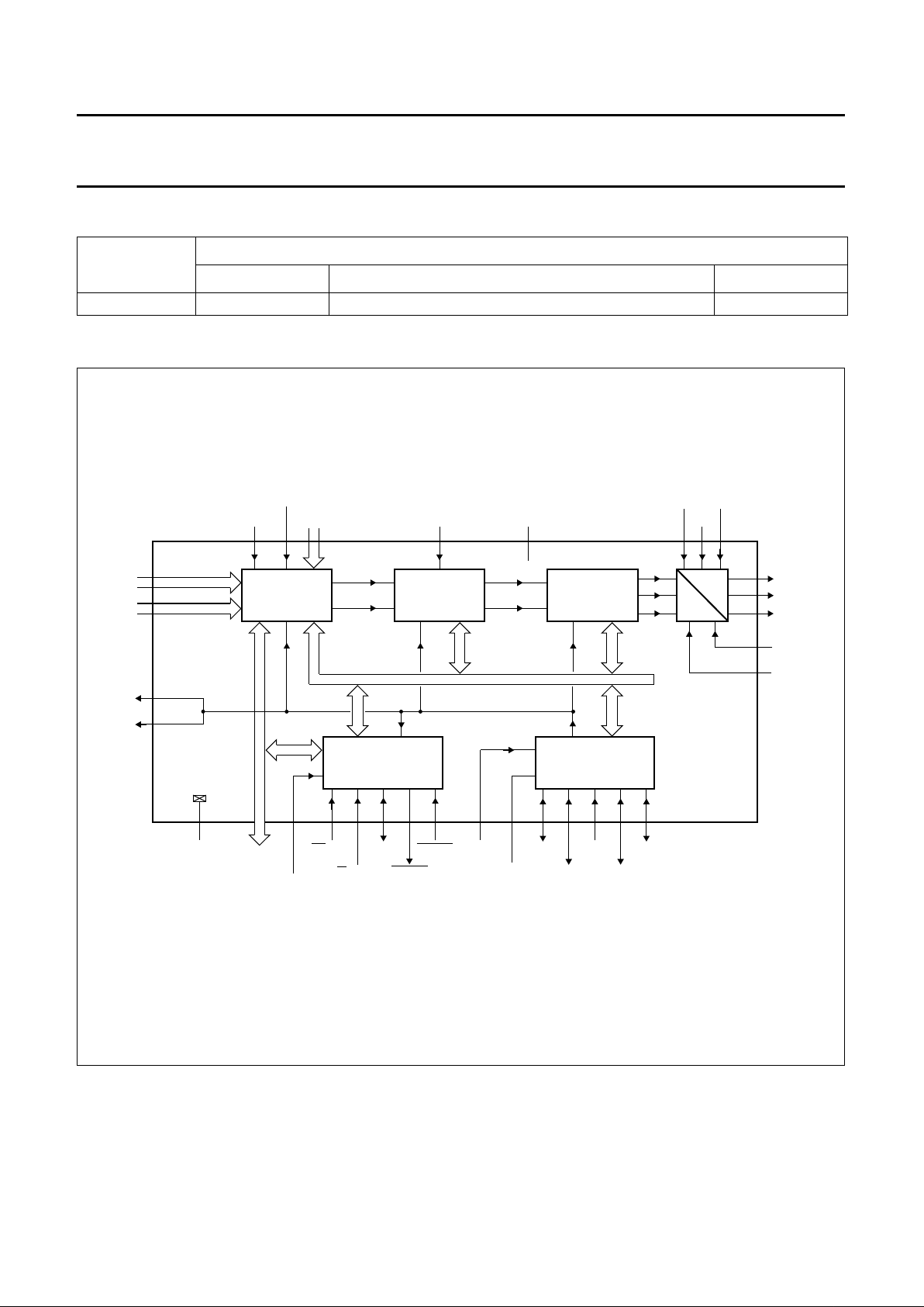
BLOCK DIAGRAM
TYPE NUMBER
PACKAGE
NAME DESCRIPTION VERSION
SAA7185WP PLCC68 plastic leaded chip carrier; 68 leads SOT188-2
ndbook, full pagewidth
CONTROL
INTERFACE
DATA
MANAGER
ENCODER
internal control bus
clock timing signals
OUTPUT
INTERFACE
SYNC
CLK
A
V
DDD1
to V
DDD3
48,50,
54,56
D
5547
53
51
49
52
46
43
RTCI
V
refH
V
DDA4
V
DDA1
88
SAA7185
8
8
8
8
8
MP7
to MP0
VP0
to VP7
8
6168
SEL_MPU
CS/SA
1,8,19
28,35,
42,62
DP0
to DP7
V
SSD1
V
SSD7
63 to 66
2 to 5
59 60 58 57 41 40 38 39 36 6 7
31
KEY
SEL_ED
OSD0
to OSD2
32 to 34
20 to 27
9 to 16
18
29
RCM1
RCM2
30
17,37,67
to
RW/SCL
A0/SDA
DTACK
RESET
XTALI
XTALO
LLC
C
ref
CDIR
RCV1
RCV2
CVBS
Y
to
I
I
CHROMA
V
SSA
V
refL
MBE733
Fig.1 Block diagram.
Page 4

1996 Jul 08 4
Philips Semiconductors Preliminary specification
Digital Video Encoder (DENC2) SAA7185
PINNING
SYMBOL PIN DESCRIPTION
V
SSD1
1 digital ground 1
DP4 2
Upper 4 bits of the Data Port. If pin 68 (SEL_MPU) is HIGH, this is the data bus of the parallel
MPU interface. If it is LOW, they are the UV lines of the Video Port.
DP5 3
DP6 4
DP7 5
RCV1 6 Raster Control 1 for Video port. Depending on the synchronization mode, this pin
receives/provides a VS/FS/FSEQ signal.
RCV2 7 Raster Control 2 for Video port. Depending on the synchronization mode, this pin
receives/provides an HS/HREF/CBL signal.
V
SSD2
8 digital ground 2
VP0 9
Video Port. This is an input for CCIR 656 compatible, multiplexed video data. If the 16-bit
DIG-TV2 format is used, this is the Y data.
VP1 10
VP2 11
VP3 12
VP4 13
VP5 14
VP6 15
VP7 16
V
DDD1
17 digital supply voltage 1
SEL_ED 18 Select Encoder Data. Selects data either from MPEG port or from video port as encoder input.
V
SSD3
19 digital ground 3
MP7 20
MPEG Port. It is an input for CCIR 656 style multiplexed YUV data.
MP6 21
MP5 22
MP4 23
MP3 24
MP2 25
MP1 26
MP0 27
V
SSD4
28 digital ground 4
RCM1 29 Raster Control 1 for MPEG port. This pin provides a VS/FS/FSEQ signal.
RCM2 30 Raster Control 2 for MPEG port. This pin provides an HS pulse for the MPEG decoder.
KEY 31 Key signal for OSD. It is active HIGH.
OSD0 32
On-Screen Display data. This is the index for the internal OSD look-up table.OSD1 33
OSD2 34
V
SSD5
35 digital ground 5
CDIR 36 Clock direction. If the CDIR input is HIGH, the circuit receives a clock signal, otherwise LLC
and CREF are generated by the internal crystal oscillator.
V
DDD2
37 digital supply voltage 2
Page 5

1996 Jul 08 5
Philips Semiconductors Preliminary specification
Digital Video Encoder (DENC2) SAA7185
LLC 38 Line-Locked Clock. This is the 27 MHz master clock for the encoder. The direction is set by
the CDIR pin.
C
ref
39 Clock Reference signal. This is the clock qualifier for DIG-TV2 compatible signals.
XTALO 40 Crystal oscillator output (to crystal).
XTALI 41 Crystal oscillator input (from crystal). If the oscillator is not used, this pin should br connected
to ground.
V
SSD6
42 digital ground 6
RTCI 43 Real Time Control Input. If the clock is provided by an SAA7151B, RTCI should be connected
to the RTCO pin of the decoder to improve the signal quality.
AP 44 Test pin. Connect to digital ground for normal operation.
SP 45 Test pin. Connect to digital ground for normal operation.
V
refL
46 Lower reference voltage input for the DACs.
V
refH
47 Upper reference voltage input for the DACs.
V
DDA1
48 Analog positive supply voltage 1 for the DACs and output amplifiers.
CHROMA 49 Analog output of the chrominance signal.
V
DDA2
50 Analog supply voltage 2 for the DACs and output amplifiers.
Y 51 Analog output of the luminance signal.
V
SSA
52 Analog ground for the DACs and output amplifiers.
CVBS 53 Analog output of the CVBS signal.
V
DDA3
54 Analog supply voltage 3 for the DACs and output amplifiers.
I
I
55 Current input for the output amplifiers, connect via a 15 kΩ resistor to V
DDA
.
V
DDA4
56 Analog supply voltage 4 for the DACs and output amplifiers.
RESET 57 Reset input, active LOW. After reset is applied, all outputs are in 3-state input mode.
The I2C-bus receiver waits for the start condition.
DTACK 58 Data acknowledge output of the parallel MPU interface, active LOW, otherwise high
impedance.
R
W/SCL 59 If pin 68 (SEL_MPU) is HIGH, this is the read/write signal of the parallel MPU interface,
otherwise it is the I2C-bus serial clock input.
A0/SDA 60 If pin 68 (SEL_MPU) is HIGH, this is the address signal of the parallel MPU interface,
otherwise it is the I
2
C-bus serial data input/output.
CS/SA 61 If pin 68 (SEL_MPU) is HIGH, this is the chip select signal of the parallel MPU interface,
otherwise it is the I2C-bus slave address select pin. LOW: slave address = 88H, HIGH = 8CH.
V
SSD7
62 digital ground 7
DP0 63
Lower 4 bits of the Data Port. If pin 68 (SEL_MPU) is HIGH, this is the data bus of the parallel
MPU interface. If it is LOW, they are the UV lines of the Video Port.
DP1 64
DP2 65
DP3 66
V
DDD3
67 digital supply voltage 3
SEL_MPU 68 Select MPU interface input. If it is HIGH, the parallel MPU interface is active, otherwise the
I
2
C-bus interface will be used.
SYMBOL PIN DESCRIPTION
Page 6

1996 Jul 08 6
Philips Semiconductors Preliminary specification
Digital Video Encoder (DENC2) SAA7185
Fig.2 Pin configuration.
handbook, full pagewidth
MBE732
SAA7185
10
11
12
13
14
15
16
17
18
19
20
21
22
23
24
25
26
60
59
58
57
56
55
54
53
52
51
50
49
48
47
46
45
44
43
42
41
40
39
38
37
36
35
34
33
32
31
30
29
28
27
61
62
63
64
65
66
67
68
1
2
3
4
5
6
7
8
9
VP1
VP2
VP3
VP4
VP5
VP6
VP7
MP7
MP6
MP5
MP4
MP3
MP2
MP1
SEL_ED
V
DDD1
V
SSD3
AP
SP
CHROMA
Y
CVBS
RESET
V
refL
V
refH
V
DDA1
V
DDA2
V
DDA3
V
DDA4
I
I
V
SSA
MP0
KEY
OSD0
OSD1
OSD2
CDIR
C
ref
XTALO
XTALI
RTCI
LLC
RCM1
RCM2
V
SSD4
V
SSD5
V
DDD2
V
SSD6
CS/SA
DP0
DP1
DP2
DP3
DP4
DP5
DP6
DP7
VP0
RCV1
RCV2
SEL_MPU
V
SSD7
V
DDD3
V
SSD1
V
SSD2
DTACK
RW/SCL
A0/SDA
Page 7

1996 Jul 08 7
Philips Semiconductors Preliminary specification
Digital Video Encoder (DENC2) SAA7185
FUNCTIONAL DESCRIPTION
The digital MPEG-compatible Video Encoder (DENC2)
encodes digital luminance and chrominance into analog
CVBS and simultaneously S-Video (Y/C) signals. NTSC-M
and PAL B/G standards also sub-standards are supported.
The basic encoder function consists of subcarrier
generation and colour modulation also insertion of
synchronization signals. Luminance and chrominance
signals are filtered in accordance with the standard
requirements RS-170-A and CCIR 624.
For ease of analog post filtering the signals are twice
oversampled with respect to pixel clock before
digital-to-analog conversion.
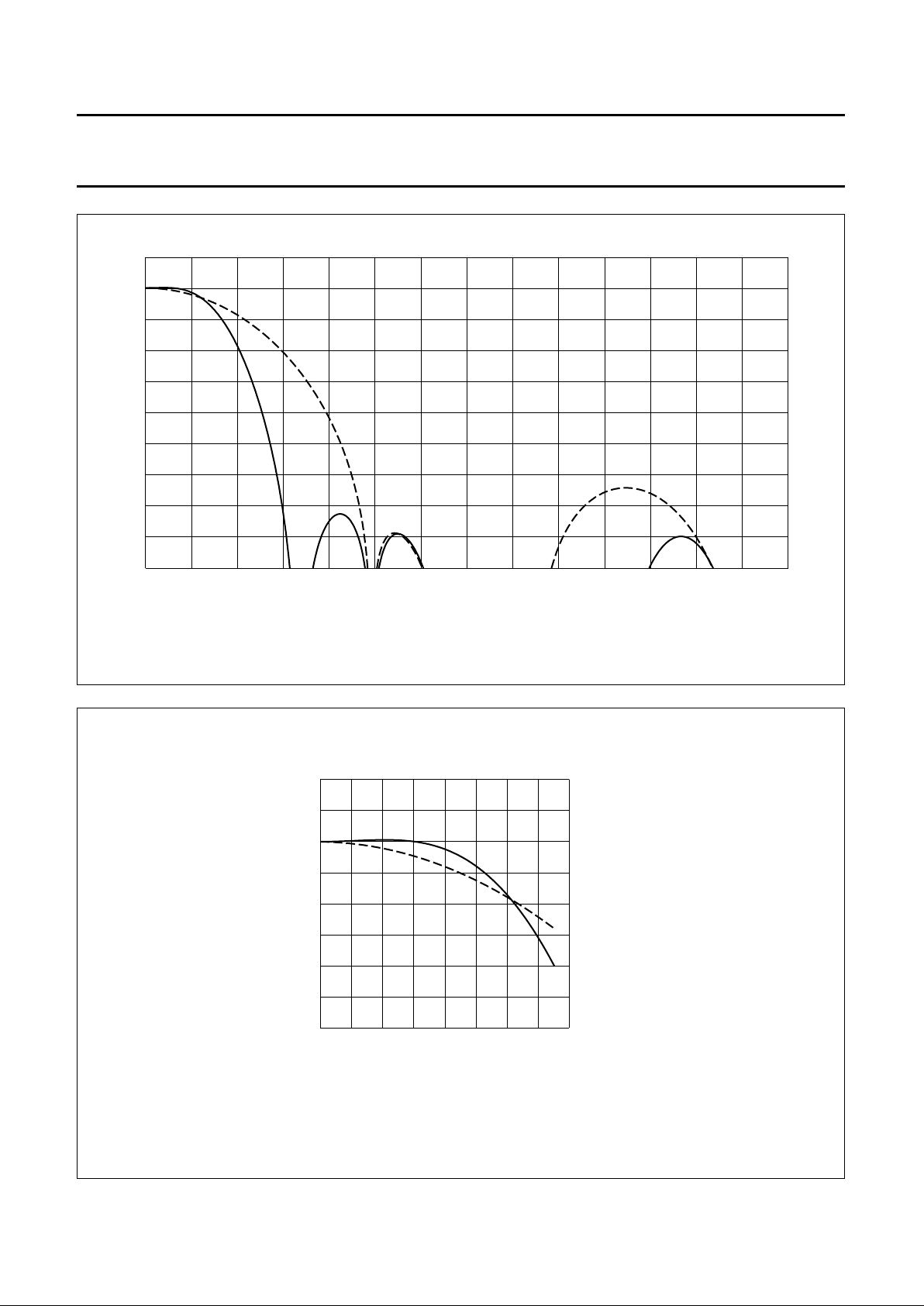
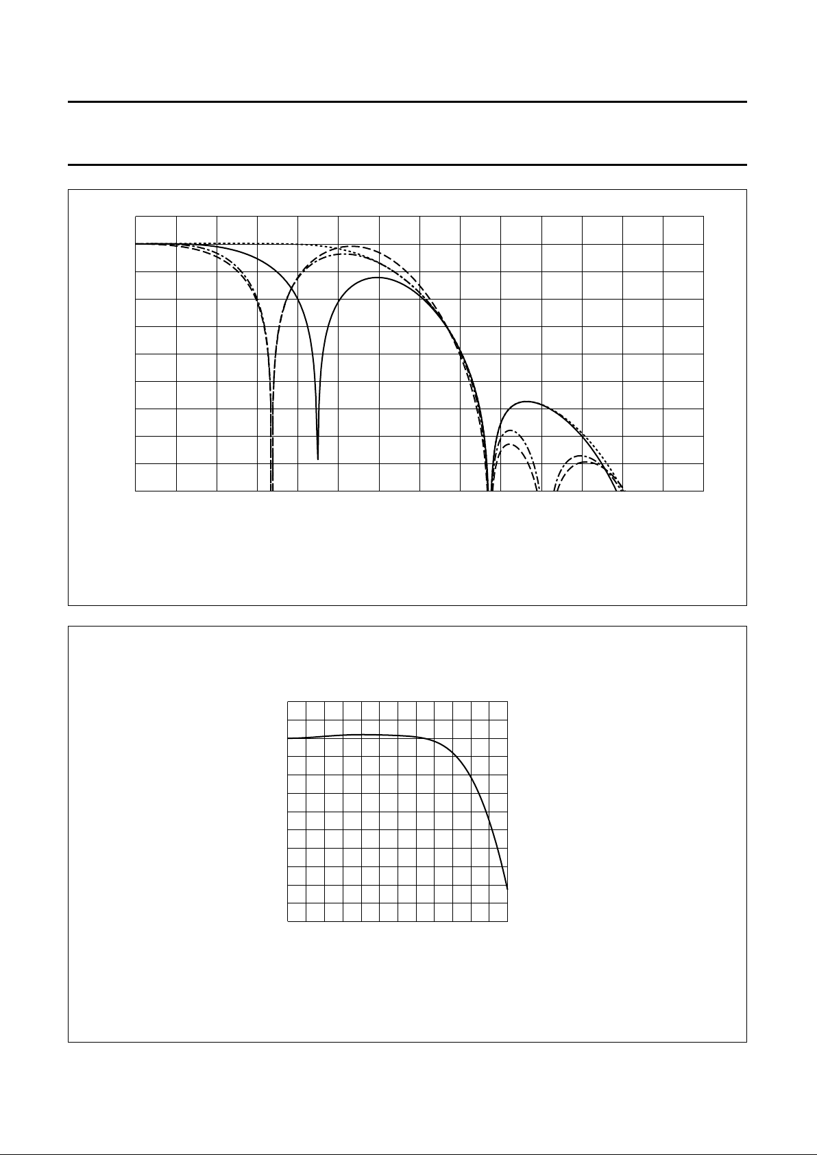
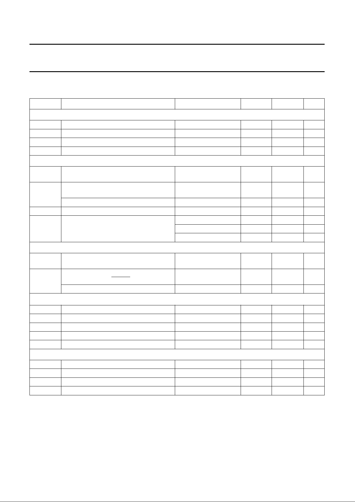
For total filter transfer characteristics see Figs 3, 4,
5 and 6. The DACs are realized with full 10-bit resolution.
The encoder provides three 8-bit wide data ports, that
serve different applications.
The MPEG Port (MP) and the Video Port (VP) accept
8 lines multiplexed Cb-Y-Cr data.
The Video Port (VP) is also able to handle DIG-TV2 family
compatible 16-bit YUV signals. In this event, the Data Port
(DP) is used for the U/V components.
The Data Port can handle the data of an 8-bit wide
microprocessor interface, alternatively.
The 8-bit multiplexed Cb-Y-Cr formats are CCIR 656
(D1 format) compatible, but the SAV, EAV etc. codes are
not decoded.
A crystal-stable master clock (LLC) of 27 MHz, which is
twice the CCIR line-locked pixel clock of 13.5 MHz, needs
to be supplied externally. Optionally, a crystal oscillator
input/output pair of pins and an on-chip clock driver is
provided. Additionally, a DMSD2 compatible clock
interface, using C
ref
(input or output) and RTC (see
“data
sheet SAA7151B”
) is available.
The DENC2 synthesizes all necessary internal signals,
colour subcarrier frequency, and synchronization signals,
from that clock. DENC2 is always timing master for the
MPEG Port (MP), but it can additionally be configured as
master or slave for the Video Port (VP).
The IC also contains Closed Caption and Extended Data
Services Encoding (Line 21); it also supports OSD via
KEY and three-bit overlay techniques by a 24 × 8 LUT.
The IC can be programmed via I2C-bus or 8-bit MPU
interface, but only one interface configuration can be
active at a time; if the 16-bit Video Port mode (VP and DP)
is being used, only the I2C-bus interface can be selected.
A number of possibilities are provided for setting of
different video parameters such as:
black and blanking level control
colour subcarrier frequency
black variable burst amplitude etc.
During reset (
RESET = LOW) and after reset is released,
all digital I/O stages are set to input mode. A reset forces
the control interfaces to abort any running bus transfer and
to set Register 3AH to contents 13H, Register 61H to
contents 0X010101b, and Register 6CH to contents 00H.
All other control registers are not influenced by a reset.
Data manager
In the Data manager, real time arbitration on the data
stream to be encoded is performed.
Depending on hardware conditions (signals on pins
SEL_ED, KEY, OSD2 to OSD0, MP7 to to MP0,
VP7 to VP0 and DP7 to DP0) and different software
programming either data from the MP port, from the
VP port, or from the OSD port are selected to be encoded
to CVBS and Y/C signals.
Optionally, the OSD colour look-up tables located in this
block, can be read out in a pre-defined sequence (8 steps
per active video line), achieving e.g. a colour bar test
pattern generator without need for an external data
source. The colour bar function is only under software
control.
Encoder
V
IDEO PATH
The encoder generates out of Y, U and V baseband
signals luminance and colour subcarrier output signals,
suitable for use as CVBS or separate Y/C signals.
Luminance is modified in gain and in offset (latter
programmable in a certain range to enable different black
level set-ups). After having been inserted a fixed
synchronization level, in accordance with standard
composite synchronization schemes, a variable blanking
level, programmable also in a certain range, is inserted.
In order to enable easy analog post filtering, luminance is
interpolated from 13.5 MHz data rate to 27 MHz data rate,
providing luminance in 10-bit resolution. This filter is also
used to define smoothed transients for synchronization
pulses and blanking period. For transfer characteristic of
the luminance interpolation filter see Figs 5 and 6.
Page 8

1996 Jul 08 8
Philips Semiconductors Preliminary specification
Digital Video Encoder (DENC2) SAA7185
Chrominance is modified in gain (programmable
separately for U and V), standard dependent burst is
inserted, before baseband colour signals are interpolated
from 6.75 MHz data rate to 27 MHz data rate. One of the
interpolation stages can be bypassed, thus providing a
higher colour bandwidth, which can be made use of for Y/C
output. For transfer characteristics of the chrominance
interpolation filter see Figs 3 and 4.
The amplitude of inserted burst is programmable in a
certain range, suitable for standard signals and for special
effects. Behind the succeeding quadrature modulator,
colour in 10-bit resolution is provided on subcarrier.
The numeric ratio between Y and C outputs is in
accordance with set standards.
C
LOSED CAPTION ENCODER
Using this circuit, data in accordance with the specification
of Closed Caption or Extended Data Service, delivered by
the control interface, can be encoded (Line 21). Two
dedicated pairs of bytes (two bytes per field), each pair
preceded by run-in clocks and framing code, are possible.
The actual line number where data is to be encoded in, can
be modified in a certain range.
Data clock frequency is in accordance with definition for
NTSC-M standard 32 times horizontal line frequency.
Data LOW at the output of the DACs corresponds to 0 IRE,
data HIGH at the output of the DACs corresponds to
approximately 50 Ω.
It is also possible to encode Closed Caption Data for 50 Hz
field frequencies at 32 times horizontal line frequency.
Output Interface
In the output interface encoded Y and C signals are
converted from digital-to-analog in 10-bit resolution both Y
and C signals are combined to a 10-bit CVBS signal, also;
in front of the summation point, the luminance signal can
optionally be fed through a further filter stage, suppressing
components in the range of subcarrier frequency. Thus, a
type of Cross Colour reduction is provided, which is useful
in a standard TV set with CVBS input.
Slopes of synchronization pulses are not affected with any
Cross Colour reduction active.
Three different filter characteristics or bypass are
available, see Fig.5.
The CVBS output occurs with the same processing delay
as the Y and C outputs. Absolute amplitudes at the input
of the DAC for CVBS is reduced by
15
⁄16 with respect to Y
and C DACs to make maximum use of conversion ranges.
Outputs of all DACs can be set together via software
control to minimum output voltage for either purpose.
Synchronization
The synchronization of the DENC2 is able to operate in
two modes; slave mode and master mode.
In the slave mode, the circuit accepts synchronization
pulses at the bidirectional RCV1 port. The timing and
trigger behaviour related to the video signal on VP (and
DP, if used) can be influenced by programming the polarity
and on-chip delay of RCV1. Active slope of RCV1 defines
the vertical phase and optionally the odd/even and colour
frame phase to be initialized, it can be also used to set the
horizontal phase.
If the horizontal phase is not be influenced by RCV1, a
horizontal pulse needs to be supplied at the RCV2 pin.
Timing and trigger behaviour can also be influenced for
RCV2.
If there are missing pulses at RCV1 and/or RCV2, the time
base of DENC2 runs free, thus an arbitrary number of
synchronization slopes may miss, but no additional pulses
(such with wrong phase) must occur.
If the vertical and horizontal phase is derived from RCV1,
RCV2 can be used for horizontal or composite blanking
input or output.
In the master mode, the time base of the circuit
continuously runs free. On the RCV1 port, the IC can
output:
• A Vertical Sync signal (VS) with 3 or 2.5 lines duration,
or
• An ODD/EVEN signal which is LOW in odd fields, or
• A field sequence signal (FSEQ) which is HIGH in the first
of 4 respectively 8 fields.
On the RCV2 port, the IC can provide a horizontal pulse
with programmable start and stop phase; this pulse can be
inhibited in the vertical blanking period to build up e.g. a
composite blanking signal.
The phase of the pulses output on RCV1 or RCV2 are
referenced to the VP port, polarity of both signals is
selectable.
Page 9

1996 Jul 08 9
Philips Semiconductors Preliminary specification
Digital Video Encoder (DENC2) SAA7185
The DENC2 is always the timing master for the source at
the MP input. The IC provides two signals for
synchronizing this source:
On the RCM1 port the same signals as on RCV1 (as
output) are available; on RCM2 the IC provides a
horizontal pulse with programmable start and stop
phase.
The length of a field also start and end of its active part
can be programmed. The active part of a field always
starts at the beginning of a line.
Control interface
DENC2 contains two control interfaces: an I
2
C-bus slave
transceiver and 8-bit parallel microprocessor interface.
The interfaces cannot be used simultaneously.
The I2C-bus interface is a standard slave transceiver,
supporting 7-bit slave addresses and 100 kbits/s
guaranteed transfer rate. It uses 8-bit subaddressing with
an auto-increment function. All registers are write only,
except one readable status byte.
Two I2C-bus slave addresses can be selected
(pin SEL_MPU must be LOW):
88H: LOW at pin 61
8CH: HIGH at pin 61.
The parallel interface is defined by:
D7 to D0 data bus
CS active-LOW chip select signal
RW read/not write signal, LOW for a write cycle
DTACK 680xx style data acknowledge (handshake),
active-LOW
A0 register select, LOW selects address, HIGH selects
data.
The parallel interface uses two registers, one
auto-incremental containing the current address of a
control register (equals subaddress with I2C-bus control),
one containing actual data. The currently addressed
register is mapped to the corresponding control register.
The status byte can be read optionally via a read access
to the address register, no other read access is provided.
Input levels and formats
DENC2 expects digital YUV data with levels (digital codes)
in accordance with CCIR 601.
Deviating amplitudes of the colour difference signals can
be compensated by independent gain control setting,
while gain for luminance is set to predefined values,
distinguishable for 7.5 IRE set-up or without set-up.
The MPEG port accepts only 8-bit multiplexed CCIR 656
compatible data.
If the I
2
C-bus interface is used, the VP port can handle
both formats, 8-bit multiplexed Cb-Y-Cr data on the
VP lines, or the 16-bit DTV2 format with the Y signal on the
VP lines and the UV signal on the DP port.
Reference levels are measured with a colour bar,
100% white, 100% amplitude and 100% saturation.
Page 10

1996 Jul 08 10
Philips Semiconductors Preliminary specification
Digital Video Encoder (DENC2) SAA7185
Table 1 CCIR signal component levels
Table 2 8-bit multiplexed format (similar to CCIR 656)
Table 3 16-bit multiplexed format (DTV2 format)
SIGNAL IRE DIGITAL LEVEL CODE
Y
016
straight binary50 126
100 235
Cb
bottom peak 16
straight binarycolourless 128
top peak 240
Cr
bottom peak 16
straight binarycolourless 128
top peak 240
TIME 0 1 2 2 4 5 6 7
Sample Cb
0
Y
0
Cr
0
Y
1
Cb
2
Y
2
Cr
2
Y
3
Luminance pixel number 0 1 2 3
Colour pixel number 0 2
TIME 0 1 2 3 4 5 6 7
Sample Y line Y
0
Y
1
Y
2
Y
3
Sample UV line Cb
0
Cr
0
Cb
2
Cr
2
Luminance pixel number 0 1 2 3
Colour pixel number 0 2
Page 11

1996 Jul 08 11
Philips Semiconductors Preliminary specification
Digital Video Encoder (DENC2) SAA7185
Bit allocation map
Table 4 Slave Receiver (Slave Address 88H or 8CH)
REGISTER FUNCTION
SUB
ADDRESS
DATA BYTE (note 1)
D7 D6 D5 D4 D3 D2 D1 D0
Null 00 00000000
↓↓
Null 39 00000000
Input port control 3A CBENB 0 0 V656 VY2C VUV2C MY2C MUV2C
OSD LUT Y0 42 OSDY07 OSDY06 OSDY05 OSDY04 OSDY03 OSDY02 OSDY01 OSDY00
OSD LUT U0 43 OSDU07 OSDU06 OSDU05 OSDU04 OSDU03 OSDU02 OSDU01 OSDU00
OSD LUT V0 44 OSDV07 OSDV06 OSDV05 OSDV04 OSDV03 OSDV02 OSDV01 OSDV00
↓↓
OSD LUT Y7 57 OSDY77 OSDY76 OSDY75 OSDY74 OSDY73 OSDY72 OSDY71 OSDY70
OSD LUT U7 58 OSDU77 OSDU76 OSDU75 OSDU74 OSDU73 OSDU72 OSDU71 OSDU70
OSD LUT V7 59 OSDV77 OSDV76 OSDV75 OSDV74 OSDV73 OSDV72 OSDV71 OSDV70
Chrominance phase 5A CHPS7 CHPS6 CHPS5 CHPS4 CHPS3 CHPS2 CHPS1 CHPS0
Gain U 5B GAINU7 GAINU6 GAINU5 GAINU4 GAINU3 GAINU2 GAINU1 GAINU0
Gain V 5C GAINV7 GAINV6 GAINV5 GAINV4 GAINV3 GAINV2 GAINV1 GAINV0
Gain U MSB, black level 5D GAINU8 0 BLCKL5 BLCKL4 BLCKL3 BLCKL2 BLCKL1 BLCKL0
Gain V MSB, blanking level 5E GAINV8 0 BLNNL5 BLNNL4 BLNNL3 BLNNL2 BLNNL1 BLNNL0
Null 5F 00000000
Cross-colour select 60 CCRS1 CCRS0 000000
Standard control 61 0 DOWN INPI1 YGS RTCE SCBW PAL FISE
Burst amplitude 62 SQP BSTA6 BSTA5 BSTA4 BSTA3 BSTA2 BSTA1 BSTA0
Subcarrier 0 63 FSC07 FSC06 FSC05 FSC04 FSC03 FSC02 FSC01 FSC00
Subcarrier 1 64 FSC15 FSC14 FSC13 FSC12 FSC11 FSC10 FSC09 FSC08
Subcarrier 2 65 FSC23 FSC22 FSC21 FSC20 FSC19 FSC18 FSC17 FSC16
Subcarrier 3 66 FSC31 FSC30 FSC29 FSC28 FSC27 FSC26 FSC25 FSC24
Line 21 odd 0 67 L21O07 L21O06 L21O05 L21O04 L21O03 L21O02 L21O01 L21O00
Line 21 odd 1 68 L21O17 L21O16 L21O15 L21O14 L21O13 L21O12 L21O11 L21O10
Line 21 even 0 69 L21E07 L21E06 L21E05 L21E04 L21E03 L21E02 L21E01 L21E00
Line 21 even 1 6A L21E17 L21E16 L21E15 L21E14 L21E13 L21E12 L21E11 L21E10
Encoder control, CC line 6B MODIN1 MODIN0 0 SCCLN4 SCCLN3 SCCLN2 SCCLN1 SCCLN0
Page 12

1996 Jul 08 12
Philips Semiconductors Preliminary specification
Digital Video Encoder (DENC2) SAA7185
Note
1. All bits labelled ‘0’ are reserved. They must be programmed with logic 0.
RCV port control 6C SRCV11 SRCV10 TRCV2 ORCV1 PRCV1 CBLF ORCV2 PRCV2
RCM, CC mode 6D 0000SRCM11 SRCM10 CCEN1 CCEN0
Horizontal trigger 6E HTRIG7 HTRIG6 HTRIG5 HTRIG4 HTRIG3 HTRIG2 HTRIG1 HTRIG0
Horizontal trigger 6F 00000HTRIG10 HTRIG09 HTRIG08
f
sc
reset mode, Vertical trigger 70 PHRES1 PHRES0 SBLBN VTRIG4 VTRIG3 VTRIG2 VTRIG1 VTRIG0
Begin MP request 71 BMRQ7 BMRQ6 BMRQ5 BMRQ4 BMRQ3 BMRQ2 BMRQ1 BMRQ0
End MP request 72 EMRQ7 EMRQ6 EMRQ5 EMRQ4 EMRQ3 EMRQ2 EMRQ1 EMRQ0
MSBs MP request 73 0 EMRQ10 EMRQ09 EMRQ08 0 BMRQ10 BMRQ09 BMRQ08
Null 74 00000000
Null 75 00000000
Null 76 00000000
Begin RCV2 output 77 BRCV7 BRCV6 BRCV5 BRCV4 BRCV3 BRCV2 BRCV1 BRCV0
End RCV2 output 78 ERCV7 ERCV6 ERCV5 ERCV4 ERCV3 ERCV2 ERCV1 ERCV0
MSBs RCV2 output 79 0 ERCV10 ERCV09 ERCV08 0 BRCV10 BRCV09 BRCV08
Field length 7A FLEN7 FLEN6 FLEN5 FLEN4 FLEN3 FLEN2 FLEN1 FLEN0
First active line 7B FAL7 FAL6 FAL5 FAL4 FAL3 FAL2 FAL1 FAL0
Last active line 7C LAL7 LAL6 LAL5 LAL4 LAL3 LAL2 LAL1 LAL0
MSBs field control 7D 0 0 LAL8 FAL8 0 0 FLEN9 FLEN8
REGISTER FUNCTION
SUB
ADDRESS
DATA BYTE (note 1)
D7 D6 D5 D4 D3 D2 D1 D0
Page 13
1996 Jul 08 13
Philips Semiconductors Preliminary specification
Digital Video Encoder (DENC2) SAA7185
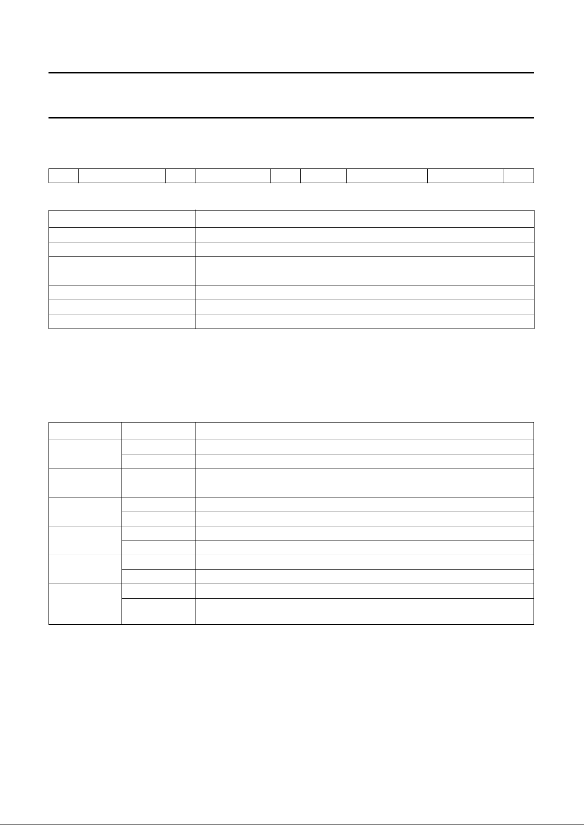
I2C-bus format
Table 5 I
2
C-bus address; see Table 6
Table 6 Explanation of Table 5
Notes
1. X is the read/write control bit; X = logic 0 is order to write; X = logic 1 is order to read, no subaddressing with read.
2. If more than 1 byte DATA is transmitted, then auto-increment of the subaddress is performed.
Slave Receiver
Table 7 Subaddress 3A
S SLAVE ADDRESS ACK SUBADDRESS ACK DATA 0 ACK -------- DATA n ACK P
PART DESCRIPTION
S START condition
Slave address 1000100X or 1000110X (note 1)
ACK acknowledge, generated by the slave
Subaddress (note 2) subaddress byte
DATA data byte
-------- continued data bytes and ACKs
P STOP condition
DATA BYTE LOGIC LEVEL DESCRIPTION
MUV2C 0 Cb/Cr data at MP are two’s complement.
1 Cb/Cr data at MP are straight binary. Default after reset.
MY2C 0 Y data at MP are two’s complement.
1 Y data at MP are straight binary. Default after reset.
VUV2C 0 Cb/Cr data input to VP or DP are two’s complement. Default after reset.
1 Cb/Cr data input to VP or DP are straight binary.
VY2C 0 Y data input to VP are two’s complement. Default after reset.
1 Y data input to VP are straight binary.
V656 0 Selects YUV 422 format on VP (8 lines Y) and DP (8 lines multiplexed Cb/Cr).
1 Selects CCIR 656 compatible format on VP (8 lines Cb, Y, Cr). Default after reset.
CBENB 0 Data from input ports are encoded. Default after reset.
1 Colour bar with programmable colours (entries of OSD_LUTs) is encoded.
The LUTs are read in upward order from index 0 to index 7.
Page 14
1996 Jul 08 14
Philips Semiconductors Preliminary specification
Digital Video Encoder (DENC2) SAA7185
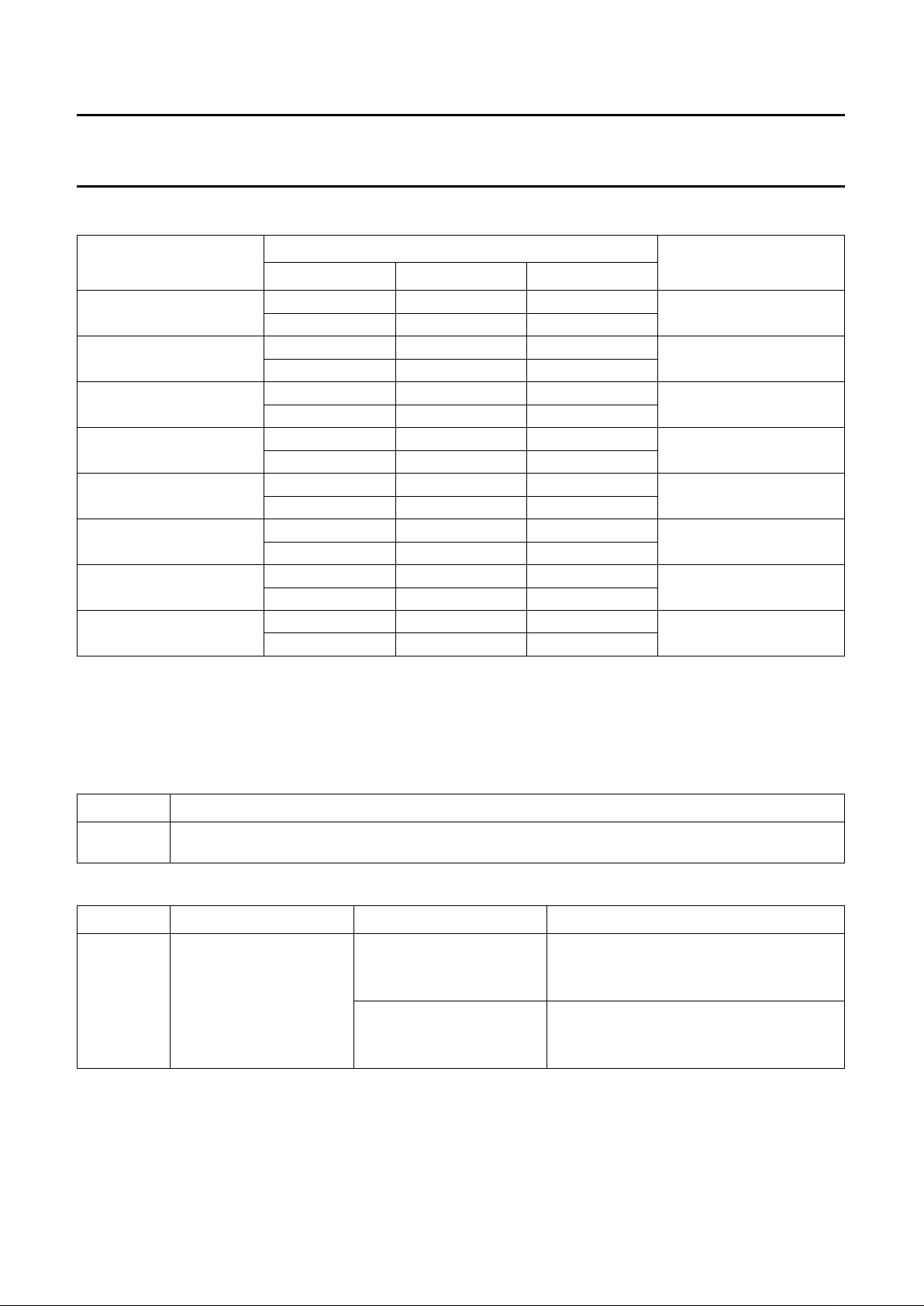
Table 8 Subaddress 42 to 59
Notes
1. Contents of OSD Look-up tables. All 8 entries are 8-bits. Data representation is in accordance with CCIR 601
(Y, Cb, Cr), but two’s complement, e.g. for a
100
⁄
100
(upper number) or
100
⁄75(lower number) colour bar.
2. For normal colour bar with CBENB = logic 1.
Table 9 Subaddress 5A
Table 10 Subaddress 5B and 5D
Notes
1. GAINU = −2.17 × nominal to +2.16 × nominal.
2. GAINU = −2.05 × nominal to +2.04 × nominal.
COLOUR
DATA BYTE (note 1)
INDEX (note 2)
OSDY OSDU OSDV
White 107 (6BH) 0 (00H) 0 (00H) 0
107 (6BH) 0 (00H) 0 (00H)
Yellow 82 (52H) 144 (90H) 18 (12H) 1
34 (22H) 172 (ACH) 14 (0Eh)
Cyan 42 (2AH) 38 (26H) 144 (90H) 2
03 (03H) 29 (1DH) 172 (ACH)
Green 17 (11H) 182 (B6H) 162 (A2H) 3
240 (F0H) 200 (C8H) 185 (B9H)
Magenta 234 (EAH) 74 (4AH) 94 (5EH) 4
212 (D4H) 56 (38H) 71 (47H)
Red 209 (D1H) 218 (DAH) 112 (70H) 5
193 (C1H) 227 (E3H) 84 (54H)
Blue 169 (A9H) 112 (70H) 238 (EEH) 6
163 (A3H) 84 (54H) 242 (F2H)
Black 144 (90H) 0 (00H) 0 (00H) 7
144 (90H) 0 (00H) 0 (00H)
DATA BYTE DESCRIPTION
CHPS Phase of encoded colour subcarrier (including burst) relative to horizontal sync. Can be adjusted in
steps of 360/256 degrees.
DATA BYTE DESCRIPTION CONDITIONS REMARKS
GAINU variable gain for Cb signal;
input representation
accordance with CCIR 601
white-to-black = 92.5 IRE
(1)
GAINU = 0 output subcarrier of U contribution = 0
GAINU = 118 (76H) output subcarrier of U contribution = nominal
white-to-black = 100 IRE
(2)
GAINU = 0 output subcarrier of U contribution = 0
GAINU = 125 (7DH) output subcarrier of U contribution = nominal
Page 15

1996 Jul 08 15
Philips Semiconductors Preliminary specification
Digital Video Encoder (DENC2) SAA7185
Table 11 Subaddress 5C and 5E
Notes
1. GAINV = −1.55 × nominal to +1.55 × nominal.
2. GAINV = −1.46 × nominal to +1.46 × nominal.
Table 12 Subaddress 5D
Notes
1. Output black level/IRE = BLCKL × 25/63 + 24; recommended value: BLCKL = 60 (3CH) normal.
2. Output black level/IRE = BLCKL × 26/63 + 24; recommended value: BLCKL = 45 (2DH) normal.
Table 13 Subaddress 5E
Notes
1. Output black level/IRE = BLNNL × 25/63 + 17; recommended value: BLNNL = 58 (3AH) normal.
2. Output black level/IRE = BLNNL × 26/63 + 17; recommended value: BLNNL = 63 (3FH) normal.
DATA BYTE DESCRIPTION CONDITIONS REMARKS
GAINV variable gain for Cr signal;
input representation
accordance with CCIR 601
white-to-black = 92.5 IRE
(1)
GAINV = 0 output subcarrier of V contribution = 0
GAINV = 165 (A5H) output subcarrier of V contribution = nominal
white-to-black = 100 IRE
(2)
GAINV = 0 output subcarrier of V contribution = 0
GAINV = 175 (AFH) output subcarrier of V contribution = nominal
DATA BYTE DESCRIPTION CONDITIONS REMARKS
BLCKL variable black level; input
representation accordance
with CCIR 601
white-to-sync = 140 IRE
(1)
BLCKL = 0 output black level = 24 IRE
BLCKL = 63 (3FH) output black level = 49 IRE
white-to-sync = 143 IRE
(2)
BLCKL = 0 output black level = 24 IRE
BLCKL = 63 (3FH) output black level = 50 IRE
DATA BYTE DESCRIPTION CONDITIONS REMARKS
BLNNL variable blanking level white-to-sync = 140 IRE
(1)
BLNNL = 0 output blanking level = 17 IRE
BLNNL = 63 (3FH) output blanking level = 42 IRE
white-to-sync = 143 IRE
(2)
BLNNL = 0 output blanking level = 17 IRE
BLNNL = 63 (3FH) output blanking level = 43 IRE
Page 16

1996 Jul 08 16
Philips Semiconductors Preliminary specification
Digital Video Encoder (DENC2) SAA7185
Table 14 Subaddress 60 (CCRS; select cross colour reduction filter in luminance)
Table 15 Subaddress 61
DATA BYTE
FUNCTION
CCRS1 CCRS0
0 0 no cross colour reduction (for overall transfer characteristic of luminance see Fig.5)
0 1 cross colour reduction #1 active (for overall transfer characteristic see Fig.5)
1 0 cross colour reduction #2 active (for overall transfer characteristic see Fig.5)
1 1 cross colour reduction #3 active (for overall transfer characteristic see Fig.5)
DATA BYTE LOGIC LEVEL DESCRIPTION
FISE 0 864 total pixel clocks per line
1 858 total pixel clocks per line; default after reset
PAL 0 NTSC encoding (non-alternating V component); default after reset
1 PAL encoding (alternating V component)
SCBW 0 enlarged bandwidth for chrominance encoding (for overall transfer characteristic of
chrominance in baseband representation see Figs 3 and 4)
1 standard bandwidth for chrominance encoding (for overall transfer characteristic of
chrominance in baseband representation see Figs 3 and 4); default after reset
RTCE 0 no real time control of generated subcarrier frequency; default after reset
1 real time control of generated subcarrier frequency through SAA7151B
(timing see Fig.9)
YGS 0 luminance gain for white − black 100 IRE
1 luminance gain for white − black 92.5 IRE including 7.5 IRE set-up of black; default
after reset
INPI 0 PAL switch phase is nominal; default after reset
1 PAL switch phase is inverted compared to nominal
DOWN 0 DACs in normal operational mode (not defined after reset, program after all zero-bits
are set to zero)
1 DACs forced to lowest output voltage (not defined after reset, program after all
zero-bits are set to zero)
Page 17

1996 Jul 08 17
Philips Semiconductors Preliminary specification
Digital Video Encoder (DENC2) SAA7185
Table 16 Subaddress 62
Notes
1. Recommended value: BSTA = 102 (66H).
2. Recommended value: BSTA = 72 (48H).
3. Recommended value: BSTA = 106 (6AH).
4. Recommended value: BSTA = 75 (4BH).
Table 17 Subaddress 63 to 66 (four bytes to program subcarrier frequency)
Notes
1. Examples:
a) NTSC-M: f
fsc
= 227.5 MHz, f
llc
= 1716 MHz → FSC = 569408543 (21F07C1FH).
b) PAL-B/G: f
fsc
= 283.7516 MHz, f
llc
= 1728 MHz → FSC = 705268427 (2A098ACBH).
DATA BYTE DESCRIPTION CONDITIONS REMARKS
BSTA amplitude of colour burst;
input representation
accordance with
CCIR 601
white-to-black = 92.5 IRE;
burst = 40 IRE; NTSC encoding
BSTA = 0 to 1.25 × nominal
(1)
white-to-black = 92.5 IRE;
burst = 40 IRE; PALencoding
BSTA = 0 to 1.76 × nominal
(2)
white-to-black = 100 IRE;
burst = 43 IRE; NTSC encoding
BSTA = 0 to 1.20 × nominal
(3)
white-to-black = 100 IRE;
burst = 43 IRE; PALencoding
BSTA = 0 to 1.67 × nominal
(4)
SQP subcarrier real time logic 0 control from SAA7151B digital
colour decoder
logic 1 not supported in current version, do
not use
DATA BYTE DESCRIPTION CONDITIONS REMARKS
FSC0 to FSC3 f
fsc
= subcarrier frequency
(in multiples of line
frequency);
f
llc
= clock frequency (in
multiples of line frequency)
see note 1
FSC3 = most significant byte
FSC0 = least significant byte
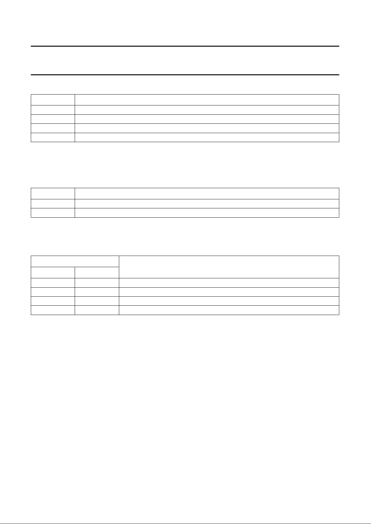
FSC round
f
fsc
f
llc
------- -
2
32
×
=
Page 18
1996 Jul 08 18
Philips Semiconductors Preliminary specification
Digital Video Encoder (DENC2) SAA7185
Table 18 Subaddress 67 to 6A
Note
1. LSBs of the respective bytes are encoded immediately after run-in and framing code, the MSBs of the respective
bytes have to carry the parity bit, in accordance with the definition of line 21 encoding format.
Table 19 Subaddress 6B
Note
1. Line = (SCCLN + 4) for M systems; line = (SCCLN + 1) for other systems.
Table 20 Logic levels and function of MODIN
DATA BYTE
(1)
DESCRIPTION
L21O0 first byte of captioning data, odd field
L21O1 second byte of captioning data, odd field
L21E0 first byte of extended data, even field
L21E1 second byte of extended data, even field
DATA BYTE DESCRIPTION
SCCLN selects the actual line, where closed caption or extended data are encoded; see note 1
MODIN defines video data of MP port or VP(DP) port to be encoded; see Table 20
DATA BYTE
FUNCTION
MODIN1 MODIN0
0 0 unconditionally from MP port
0 1 from MP port, if pin SEL_ED = HIGH; otherwise from VP port
1 0 unconditionally from VP port
1 1 from VP port, if pin SEL_ED = HIGH; otherwise from MP port
Page 19
1996 Jul 08 19
Philips Semiconductors Preliminary specification
Digital Video Encoder (DENC2) SAA7185
Table 21 Subaddress 6C
Table 22 Logic levels and function of SRCV1
Table 23 Subaddress 6D
DATA BYTE LOGIC LEVEL DESCRIPTION
PRCV2 0 polarity of RCV2 as output is active HIGH, rising edge is taken when input,
respectively; default after reset
1 polarity of RCV2 as output is active LOW, falling edge is taken when input,
respectively
ORCV2 0 pin RCV2 is switched to input; default after reset
1 pin RCV2 is switched to output
CBLF 0 if ORCV2 = HIGH, pin RCV2 provides an HREF signal (Horizontal Reference Pulse
that is HIGH during active portion of line, also during vertical blanking Interval);
default after reset
1 if ORCV2 = LOW, signal input to RCV2 is used for horizontal synchronization only
(if TRCV2 = 1); default after reset
if ORCV2 = LOW, signal input to RCV2 is used for horizontal synchronization
(if TRCV2 = 1) also as an internal blanking signal
PRCV1 0 polarity of RCV1 as output is active HIGH, rising edge is taken when input,
respectively; default after reset
1 polarity of RCV1 as output is active LOW, falling edge is taken when input,
respectively
ORCV1 0 pin RCV1 is switched to input; default after reset
1 pin RCV1 is switched to output
TRCV2 0 horizontal synchronization is taken from RCV1 port; default after reset
1 horizontal synchronization is taken from RCV2 port
SRCV1 − defines signal type on pin RCV1; see Table 22
DATA BYTE
AS OUTPUT AS INPUT FUNCTION
SRCV11 SRCV10
0 0 VS VS Vertical Sync each field; default after reset
0 1 FS FS Frame Sync (odd/even)
1 0 FSEQ FSEQ Field Sequence, vertical sync every fourth field
(FISE = 1) or eighth field (FISE = 0)
11 −−not applicable
DATA BYTE DESCRIPTION
CCEN enables individual line 21 encoding; see Table 24
SRCM defines signal type on pin RCM1; see Table 25
Page 20
1996 Jul 08 20
Philips Semiconductors Preliminary specification
Digital Video Encoder (DENC2) SAA7185
Table 24 Logic levels and function of CCEN
Table 25 Logic levels and function of SRCM
Table 26 Subaddress 6E to 6F
Table 27 Subaddress 70
Note
1. If cross-colour reduction is programmed, it is active between FAL and LAL in both events.
DATA BYTE
FUNCTION
CCEN1 CCEN0
0 0 line 21 encoding OFF
0 1 enables encoding in field 1 (odd)
1 0 enables encoding in field 2 (even)
1 1 enables encoding in both fields
DATA BYTE
AS OUTPUT FUNCTION
SRCM1 SRCM0
0 0 VS Vertical Sync each field
0 1 FS Frame Sync (odd/even)
1 0 FSEQ Field Sequence, vertical sync every fourth field (FISE = 1) or eighth
field (FISE = 0)
11 −not applicable
DATA BYTE DESCRIPTION
HTRIG sets the Horizontal Trigger phase related to signal on RCV1 or RCV2 input
values above 1715 (FISE = 1) or 1727 (FISE = 0) are not allowed
increasing HTRIG decreases delays of all internally generated timing signals
reference mark: analog output horizontal sync (leading slope) coincides with active edge of RCV
used for triggering at HTRIG = 032H
DATA BYTE LOGIC LEVEL DESCRIPTION
VTRIG − sets the Vertical TRIGger phase related to signal on RCV1 input
increasing VTRIG decreases delays of all internally generated timing signals,
measured in half lines
variation range of VTRIG=0to31(1FH)
SBLBN 0 vertical blanking is defined by programming of FAL and LAL
1 vertical blanking is forced automatically at least during field synchronization and
equalization pulses; note 1
PHRES − selects the phase reset mode of the colour subcarrier generator; see Table28
Page 21

1996 Jul 08 21
Philips Semiconductors Preliminary specification
Digital Video Encoder (DENC2) SAA7185
Table 28 Logic levels and function of PHRES
Table 29 Subaddress 71 to 73
Table 30 Subaddress 77 to 79
Table 31 Subaddress 7A to 7D
S
UBADDRESSES
In subaddresses 5B, 5C, 5D, 5E and 62 all IRE values are rounded up.
DATA BYTE
FUNCTION
PHRES1 PHRES0
0 0 no reset
0 1 reset every two lines
1 0 reset every eight fields
1 1 reset every four fields
DATA BYTE DESCRIPTION
BMRQ beginning of MP ReQuest signal (RCM2)
values above 1715 (FISE = 1) or 1727 (FISE = 0) are not allowed
first active pixel at analog outputs (corresponding input pixel coinciding with RCM2) at
BMRQ = 0F9H (115H)
EMRQ end of MP ReQuest signal (RCM2)
values above 1715 (FISE = 1) or 1727 (FISE = 0) are not allowed
last active pixel at analog outputs (corresponding input pixel coinciding with RCM2) at
EMRQ = 686H (690H)
DATA BYTE DESCRIPTION
BRCV beginning of output signal on RCV2 pin
values above 1715 (FISE = 1) or 1727 (FISE = 0) are not allowed
first active pixel at analog outputs (corresponding input pixel coinciding with RCV2) at
BRCV = 0F9H (115H)
ERCV end of output signal on RCV2 pin
values above 1715 (FISE = 1) or 1727 (FISE = 0) are not allowed
last active pixel at analog outputs (corresponding input pixel coinciding with RCV2) at
ERCV = 686H (690H)
DATA BYTE DESCRIPTION
FLEN Length of a Field = FLEN + 1, measured in half lines
valid range is limited to 524 to 1022 (FISE = 1) respectively 624 to 1022 (FISE = 0),
FLEN should be even
FAL First Active Line after vertical blanking interval = FAL + 1, measured in lines
FAL = 0 coincides with the first field synchronization pulse
LAL Last Active Line before vertical blanking interval = LAL + 1, measured in lines
LAL = 0 coincides with the first field synchronization pulse
Page 22

1996 Jul 08 22
Philips Semiconductors Preliminary specification
Digital Video Encoder (DENC2) SAA7185
Slave Transmitter
Table 32 Slave Transmitter (slave address 89H or 8DH)
Table 33 No subaddress
REGISTER
FUNCTION
SUBADDRESS
DATA BYTE
D7 D6 D5 D4 D3 D2 D1 D0
Status byte − VER2 VER1 VER0 CCRDE CCRDO FSQ2 FSQ1 FSQ0
DATA BYTE DESCRIPTION
VER Version identification of the device. It will be changed with all versions of the IC that have different
programming models. Current Version is 000 binary.
CCRDE Closed caption bytes of the even field have been encoded.
The bit is reset after information has been written to the subaddresses 69 and 6A. It is set immediately
after the data have been encoded.
CCRDO Closed caption bytes of the odd field have been encoded.
The bit is reset after information has been written to the subaddresses 67 and 68. It is set immediately
after the data have been encoded.
FSQ State of the internal field sequence counter.
Bit 0 (FSQ0) gives the odd/even information; odd = LOW, even = HIGH.
Page 23
1996 Jul 08 23
Philips Semiconductors Preliminary specification
Digital Video Encoder (DENC2) SAA7185
Fig.3 Chrominance transfer characteristic 1.
handbook, full pagewidth
6 8 10 12 14
6
0
024
MBE737
−6
−12
−18
−30
−24
−36
−42
−54
−48
f (MHz)
G
v
(dB)
(1) (2)
(1) SCBW = 1.
(2) SCBW = 0.
Fig.4 Chrominance transfer characteristic 2.
handbook, halfpage
0 0.4 0.8 1.6
2
0
−4
−6
−2
MBE735
1.2
f (MHz)
G
v
(dB)
(1)
(2)
(1) SCBW = 1.
(2) SCBW = 0.
Page 24
1996 Jul 08 24
Philips Semiconductors Preliminary specification
Digital Video Encoder (DENC2) SAA7185
Fig.5 Luminance transfer characteristic 1.
handbook, full pagewidth
6 8 10 12 14
6
0
024
MBE738
−6
−12
−18
−30
−24
−36
−42
−54
−48
f (MHz)
G
v
(dB)
(1)
(2)
(3)
(4)
(1) CCRS1 = 0; CCRS0 = 1.
(2) CCRS1 = 1; CCRS0 = 0.
(3) CCRS1 = 1; CCRS0 = 1.
(4) CCRS1 = 0; CCRS0 = 0.
Fig.6 Luminance transfer characteristic 2
handbook, halfpage
02 6
1
0
−1
−2
−3
−4
−5
MBE736
4
f (MHz)
G
v
(dB)
CCRS1 = 0; CCRS0 = 0.
Page 25
1996 Jul 08 25
Philips Semiconductors Preliminary specification
Digital Video Encoder (DENC2) SAA7185
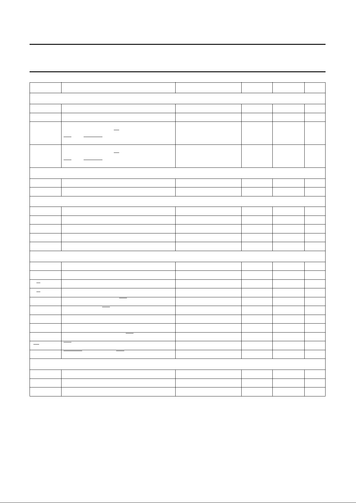
CHARACTERISTICS
V
DDD
= 4.5 to 5.5 V; T
amb
= 0 to 70 °C; unless otherwise specified.
SYMBOL PARAMETER CONDITIONS MIN. MAX. UNIT
Supply
V
DDD
digital supply voltage 4.5 5.5 V
V
DDA
analog supply voltage 4.75 5.25 V
I
DDD
digital supply current note 1 − 170 mA
I
DDA
analog supply current note 1 − 55 mA
Inputs
V
IL
LOW level input voltage
(except LLC, SDA, SCL, AP, SP and XTALI)
−0.5 +0.8 V
V
IH
HIGH level input voltage
(except LLC, SDA, SCL, AP, SP and XTALI)
2.0 V
DDD
+ 0.5 V
HIGH level input voltage (LLC) 2.4 V
DDD
+ 0.5 V
V
LI
input leakage current − 1 µA
C
I
input capacitance clocks operating − 10 pF
data available − 8pF
I/Os at high impedance − 8pF
Outputs
V
OL
LOW level output voltage
(except SDA and XTALO)
note 2 0 0.6 V
V
OH
HIGH level output voltage
(except LLC, SDA, DTACK and XTALO)
note 2 2.4 V
DDD
+ 0.5 V
HIGH level output voltage (LLC) note 2 2.6 V
DDD
+ 0.5 V
I
2
C-bus; SDA and SCL
V
IL
LOW level input voltage −0.5 +1.5 V
V
IH
HIGH level input voltage 3.0 V
DDD
+ 0.5 V
I
I
input current VI= LOW or HIGH −10 +10 µA
V
OL
LOW level output voltage (SDA) IOL=3mA − 0.4 V
I
O
output current during acknowledge 3 − mA
Clock timing (LLC)
T
LLC
cycle time note 3 34 41 ns
δ duty factor t
HIGH/TLLC
note 4 40 60 %
t
r
rise time note 3 − 5ns
t
f
fall time note 3 − 6ns
Page 26
1996 Jul 08 26
Philips Semiconductors Preliminary specification
Digital Video Encoder (DENC2) SAA7185
Input timing
t
SU;CREF
input data set-up time (C
ref
)6−ns
t
HD;CREF
input data hold time (C
ref
)3−ns
t
SU
input data set-up time (any other except
SEL_MPU, CDIR, RW/SCL, A0/SDA,
CS/SA, RESET, AP and SP)
6 − ns
t
HD
input data hold time (any other except
SEL_MPU, CDIR, RW/SCL, A0/SDA,
CS/SA, RESET, AP and SP)
3 − ns
Crystal oscillator
f
n
nominal frequency (usually 27 MHz) 3rd harmonic − 30 MHz
∆f/f
n
permissible deviation of nominal frequency note 5 −50 +50 10
−6
CRYSTAL SPECIFICATION
T
amb
operating ambient temperature 0 70 °C
C
L
load capacitance 8 − pF
R
S
series resistance − 80 Ω
C
1
motional capacitance (typical) 1.5 −20% 1.5 +20% fF
C
0
parallel capacitance (typical) 3.5 −20% 3.5 +20% pF
MPU interface timing
t
AS
address set-up time note 6 9 − ns
t
AH
address hold time 0 − ns
t
RWS
read/write set-up time note 6 9 − ns
t
RWH
read/write hold time 0 − ns
t
DD
data bus floating from CS (read) notes 7, 8 and 9; n = 9 − 400 ns
t
DF
data valid from CS (read) notes 7 and 8; n = 5 − 255 ns
t
DS
data bus set-up time (write) note 6 9 − ns
t
DH
data bus hold time (write) note 6 9 − ns
t
ACS
acknowledge delay from CS notes 7 and 8; n = 11 − 475 ns
t
CSD
CS HIGH from acknowledge 0 − ns
t
DAT
DTACK floating from CS HIGH notes 7 and 8; n = 7 − 330 ns
Data and reference signal output timing
C
L
output load capacitance 7.5 40 pF
t
OH
output hold time 4 − ns
t
OD
output delay time C
ref
in output mode − 25 ns
SYMBOL PARAMETER CONDITIONS MIN. MAX. UNIT
Page 27
1996 Jul 08 27
Philips Semiconductors Preliminary specification
Digital Video Encoder (DENC2) SAA7185
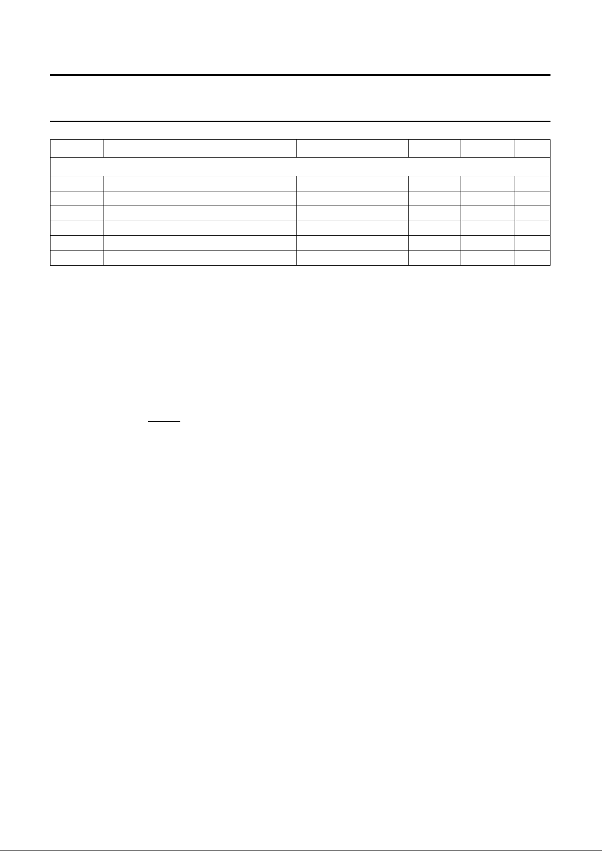
Notes
1. At maximum supply voltage with highly active input signals.
2. The levels have to be measured with load circuits of 1.2 kΩ to 3.0 V (standard TTL load) and C
L
= 25 pF.
3. The data is for both input and output direction.
4. With LLC in input mode. In output mode, with a crystal connected to XTALO/XTALI duty factor is typically 50%.
5. If an internal oscillator is used, crystal deviation of nominal frequency is directly proportional to the deviation of
subcarrier frequency and line/field frequency.
6. The value is calculated via equation
7. The value depends on the clock frequency. The numbers given are calculated with f
LLC
= 27 MHz.
8. The values given are calculated via equation
9. The falling edge of DTACK will always occur1 × LLC after data is valid.
10. For full digital range, without load, V
DDA
= 5.0 V. The typical voltage swing is 2.0 V, the typical minimum output
voltage (digital zero at DAC) is 0.2 V.
CHROMA, Y and CVBS outputs
V
o(p-p)
output signal voltage (peak-to-peak value) note 10 1.9 2.1 V
R
I
internal serial resistance 18 35 Ω
R
L
output load resistance 80 −Ω
B output signal bandwidth of DACs −3dB 10 − MHz
ILE LF integral linearity error of DACs −±2 LSB
DLE LF differential linearity error of DACs −±1 LSB
SYMBOL PARAMETER CONDITIONS MIN. MAX. UNIT
ttSUtHD+=
t
dmaxtOD
nt
LLCtLLCtSU
++×+=
Page 28
1996 Jul 08 28
Philips Semiconductors Preliminary specification
Digital Video Encoder (DENC2) SAA7185
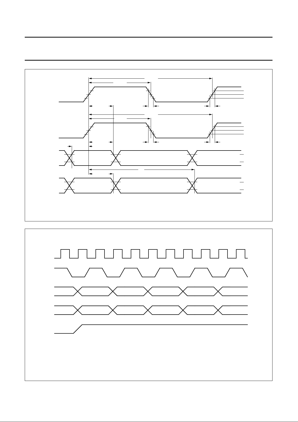
Fig.7 Clock data timing.
handbook, full pagewidth
MBE742
LLC clock output
0.6 V
1.5 V
2.6 V
2.0 V
0.8 V
2.4 V
0.6 V
input data
output data
not valid
valid
valid
not valid
valid
valid
LLC clock input
0.8 V
1.5 V
2.4 V
t
HIGH
t
HD; DAT
T
LLC
t
HIGH
T
LLC
t
d
t
HD; DAT
t
HD; DAT
t
SU; DAT
t
f
t
f
t
r
t
r
Fig.8 Digital TV timing.
The data demultiplexing phase is coupled to the internal horizontal phase.
The C
ref
signal applies only for the 16 lines digital TV format, because these signals are only valid in 13.5 MHz.
The phase of the RCV2 signal is programmed to 0F8h (115H for 50 Hz) in this example in output mode (BRCV2).
handbook, full pagewidth
LLC
CREF
VP(n) Y(0)
Cb(0)
Y(1)
Cr(0)
Y(2)
Cb(2)
Y(3)
Cr(2)
Y(4)
Cb(4)DP(n)
RCV2
MBE739
Page 29
1996 Jul 08 29
Philips Semiconductors Preliminary specification
Digital Video Encoder (DENC2) SAA7185
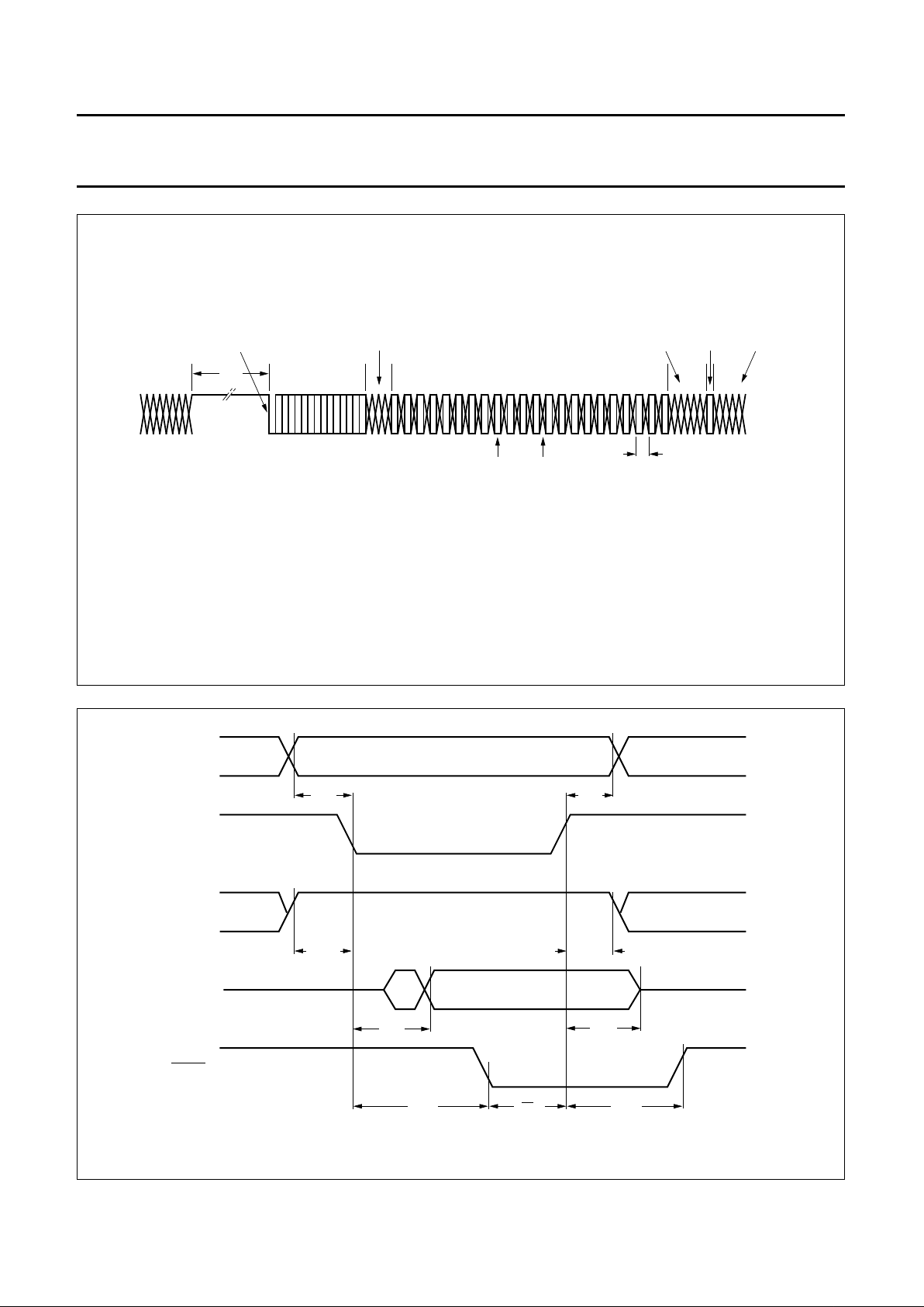
Fig.9 RTCI timing.
(1) Sequence bit:
PAL = logic 0 then (R − Y) line normal; PAL = logic 1 then (R − Y) line inverted.
NTSC = logic 0 then no change.
(2) Reserved bits: 236 with 50 Hz systems; 233 with 60 Hz systems.
handbook, full pagewidth
128 13 0 21
RTCI
HPLL
increment
H/L transition
count start
4 bits
reserved
valid
sample
invalid
sample
not used in DENC2
0
sequence
bit (1)
5 bits
reserved
8/LLC
reserved (2)
MBE743
Fig.10 MPU interface timing (READ cycle).
handbook, full pagewidth
A0
CSN
RWN
D(7 to 0)
DTACK
t
AS
t
AH
t
RWS
t
RWH
t
DAT
t
ACS
t
DF
t
CSD
t
DD
MBE740
Page 30
1996 Jul 08 30
Philips Semiconductors Preliminary specification
Digital Video Encoder (DENC2) SAA7185
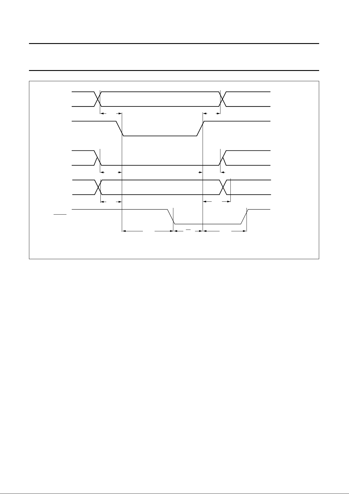
Fig.11 MPU interface timing (WRITE cycle).
handbook, full pagewidth
A0
CSN
RWN
D(7 to 0)
DTACK
t
AS
t
AH
t
RWS
t
RWH
t
DAT
t
ACS
t
DF
t
CSD
t
DS
MBE741
Page 31
1996 Jul 08 31
Philips Semiconductors Preliminary specification
Digital Video Encoder (DENC2) SAA7185
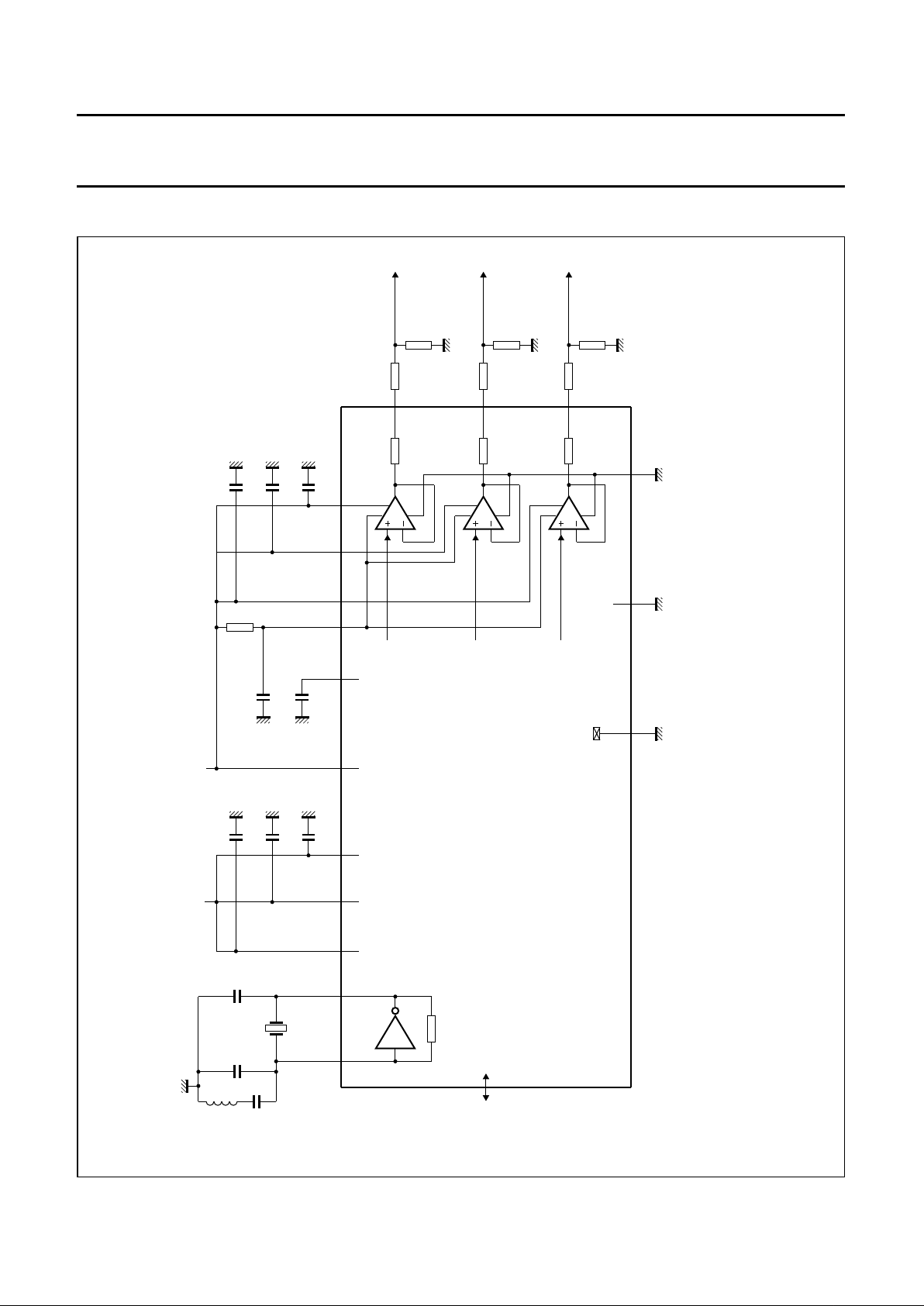
APPLICATION INFORMATION
handbook, full pagewidth
(1)
(3)
49
(1)
51
(1)
53
52
V
SSA
0.62 V (p-p)
(2)
CHROMA
75 Ω
75
35 Ω 20 Ω
20 Ω
12 Ω
35 Ω
35 Ω
Ω
75 Ω
1.0 V (p-p)
(2)
Y
1.23 V (p-p)
(2)
CVBS
V
SSA
V
SSA
V
SSA
48
50
V
DDA2
V
DDA1
V
DDA3
DAC3
DAC2
DAC1
I
I
V
refH
545547
46
V
refL
1, 8, 19, 28,
35, 42, 62
V
SSD1
to V
SSD7
0.1 µF
0.1 µF
15 kΩ
V
SSAVSSA
V
DDA4
56
+ 5 V analog
0.1 µF
V
SSA
0.1 µF
V
SSA
0.1 µF
V
SSA
6737
V
DDD2
V
DDD3
V
DDD1
17
0.1 µF
V
SSD
0.1 µF
V
SSD
0.1 µF
V
SSD
+ 5 V digital
10
pF
3rd
harmonic
X1
27.0 MHz
XTAL0
40
XTAL1
41
10
pF
1
nF
V
SSD
10
µH
digital
inputs and
outputs
SAA7185
MBE734
Fig.12 Application environment of the DENC2.
(1) Typical value.
(2) For 100/100 colour bar.
(3) Philips 12NC ordering code: 4312 065 02341.
Page 32
1996 Jul 08 32
Philips Semiconductors Preliminary specification
Digital Video Encoder (DENC2) SAA7185
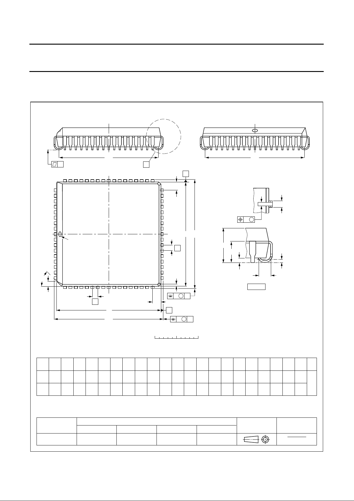
PACKAGE OUTLINE
REFERENCES
OUTLINE
VERSION
EUROPEAN
PROJECTION
ISSUE DATE
IEC JEDEC EIAJ
Note
1. Plastic or metal protrusions of 0.01 inches maximum per side are not included.
SOT188-2
4460
68
1
9
10 26
43
27
61
detail X
(A )
3
b
p
w M
A
1
A
A
4
L
p
b
1
β
k
1
k
X
y
e
E
B
D
H
E
H
v M
B
D
Z
D
A
Z
E
e
v M
A
pin 1 index
112E10 MO-047AC
0 5 10 mm
scale
92-11-17
95-03-11
PLCC68: plastic leaded chip carrier; 68 leads
SOT188-2
UNIT A
A
min. max. max. max. max.
1
A
4
b
p
E
(1)
(1) (1)
eH
E
Z
ywv β
mm
4.57
4.19
0.51
3.30
0.53
0.33
0.021
0.013
1.27
0.51
2.16
45
o
0.18 0.100.18
DIMENSIONS (millimetre dimensions are derived from the original inch dimensions)
D
(1)
24.33
24.13
H
D
25.27
25.02
E
Z
2.16
D
b
1
0.81
0.66
k
1.22
1.07
k
1
0.180
0.165
0.020
0.13
A
3
0.25
0.01
0.05
0.020
0.085
0.007 0.0040.007
L
p
1.44
1.02
0.057
0.040
0.958
0.950
24.33
24.13
0.958
0.950
0.995
0.985
25.27
25.02
0.995
0.985
e
E
e
D
23.62
22.61
0.930
0.890
23.62
22.61
0.930
0.890
0.085
0.032
0.026
0.048
0.042
E
e
inches
D
e
Page 33

1996 Jul 08 33
Philips Semiconductors Preliminary specification
Digital Video Encoder (DENC2) SAA7185
SOLDERING
Introduction
There is no soldering method that is ideal for all IC
packages. Wave soldering is often preferred when
through-hole and surface mounted components are mixed
on one printed-circuit board. However, wave soldering is
not always suitable for surface mounted ICs, or for
printed-circuits with high population densities. In these
situations reflow soldering is often used.
This text gives a very brief insight to a complex technology.
A more in-depth account of soldering ICs can be found in
our
“IC Package Databook”
(order code 9398 652 90011).
Reflow soldering
Reflow soldering techniques are suitable for all PLCC
packages.
The choice of heating method may be influenced by larger
PLCC packages (44 leads, or more). If infrared or vapour
phase heating is used and the large packages are not
absolutely dry (less than 0.1% moisture content by
weight), vaporization of the small amount of moisture in
them can cause cracking of the plastic body. For more
information, refer to the Drypack chapter in our
“Quality
Reference Handbook”
(order code 9397 750 00192).
Reflow soldering requires solder paste (a suspension of
fine solder particles, flux and binding agent) to be applied
to the printed-circuit board by screen printing, stencilling or
pressure-syringe dispensing before package placement.
Several techniques exist for reflowing; for example,
thermal conduction by heated belt. Dwell times vary
between 50 and 300 seconds depending on heating
method. Typical reflow temperatures range from
215 to 250 °C.
Preheating is necessary to dry the paste and evaporate
the binding agent. Preheating duration: 45 minutes at
45 °C.
Wave soldering
Wave soldering techniques can be used for all PLCC
packages if the following conditions are observed:
• A double-wave (a turbulent wave with high upward
pressure followed by a smooth laminar wave) soldering
technique should be used.
• The longitudinal axis of the package footprint must be
parallel to the solder flow.
• The package footprint must incorporate solder thieves at
the downstream corners.
During placement and before soldering, the package must
be fixed with a droplet of adhesive. The adhesive can be
applied by screen printing, pin transfer or syringe
dispensing. The package can be soldered after the
adhesive is cured.
Maximum permissible solder temperature is 260 °C, and
maximum duration of package immersion in solder is
10 seconds, if cooled to less than 150 °C within
6 seconds. Typical dwell time is 4 seconds at 250 °C.
A mildly-activated flux will eliminate the need for removal
of corrosive residues in most applications.
Repairing soldered joints
Fix the component by first soldering two diagonallyopposite end leads. Use only a low voltage soldering iron
(less than 24 V) applied to the flat part of the lead. Contact
time must be limited to 10 seconds at up to 300 °C. When
using a dedicated tool, all other leads can be soldered in
one operation within 2 to 5 seconds between
270 and 320 °C.
Page 34
1996 Jul 08 34
Philips Semiconductors Preliminary specification
Digital Video Encoder (DENC2) SAA7185
DEFINITIONS
LIFE SUPPORT APPLICATIONS
These products are not designed for use in life support appliances, devices, or systems where malfunction of these
products can reasonably be expected to result in personal injury. Philips customers using or selling these products for
use in such applications do so at their own risk and agree to fully indemnify Philips for any damages resulting from such
improper use or sale.
PURCHASE OF PHILIPS I
2
C COMPONENTS
Data sheet status
Objective specification This data sheet contains target or goal specifications for product development.
Preliminary specification This data sheet contains preliminary data; supplementary data may be published later.
Product specification This data sheet contains final product specifications.
Limiting values
Limiting values given are in accordance with the Absolute Maximum Rating System (IEC 134). Stress above one or
more of the limiting values may cause permanent damage to the device. These are stress ratings only and operation
of the device at these or at any other conditions above those given in the Characteristics sections of the specification
is not implied. Exposure to limiting values for extended periods may affect device reliability.
Application information
Where application information is given, it is advisory and does not form part of the specification.
Purchase of Philips I
2
C components conveys a license under the Philips’ I2C patent to use the
components in the I2C system provided the system conforms to the I2C specification defined by
Philips. This specification can be ordered using the code 9398 393 40011.
Page 35

1996 Jul 08 35
Philips Semiconductors Preliminary specification
Digital Video Encoder (DENC2) SAA7185
NOTES
Page 36

Internet: http://www.semiconductors.philips.com/ps/
(1) SAA7185_2 June 26, 1996 11:51 am
Philips Semiconductors – a worldwide company
© Philips Electronics N.V. 1996 SCA50
All rights are reserved. Reproduction in whole or in part is prohibited without the prior written consent of the copyright owner.
The information presented in this document does not form part of any quotation or contract, is believed to be accurate and reliable and may be changed
without notice. No liability will be accepted by the publisher for any consequence of its use. Publication thereof does not convey nor imply any license
under patent- or other industrial or intellectual property rights.
Netherlands: Postbus 90050, 5600 PB EINDHOVEN, Bldg. VB,
Tel. +31 40 27 83749, Fax. +31 40 27 88399
New Zealand: 2 Wagener Place, C.P.O. Box 1041, AUCKLAND,
Tel. +64 9 849 4160, Fax. +64 9 849 7811
Norway: Box 1, Manglerud 0612, OSLO,
Tel. +47 22 74 8000, Fax. +47 22 74 8341
Philippines: Philips Semiconductors Philippines Inc.,
106 Valero St. Salcedo Village, P.O. Box 2108 MCC, MAKATI,
Metro MANILA, Tel. +63 2 816 6380, Fax. +63 2 817 3474
Poland: Ul. Lukiska 10, PL 04-123 WARSZAWA,
Tel. +48 22 612 2831, Fax. +48 22 612 2327
Portugal: see Spain
Romania: see Italy
Russia: Philips Russia, Ul. Usatcheva 35A, 119048 MOSCOW,
Tel. +7 095 926 5361, Fax. +7 095 564 8323
Singapore: Lorong 1, Toa Payoh, SINGAPORE 1231,
Tel. +65 350 2538, Fax. +65 251 6500
Slovakia: see Austria
Slovenia: see Italy
South Africa: S.A. PHILIPS Pty Ltd., 195-215 Main Road Martindale,
2092 JOHANNESBURG, P.O. Box 7430 Johannesburg 2000,
Tel. +27 11 470 5911, Fax. +27 11 470 5494
South America: Rua do Rocio 220, 5th floor, Suite 51,
04552-903 São Paulo, SÃO PAULO - SP, Brazil,
Tel. +55 11 821 2333, Fax. +55 11 829 1849
Spain: Balmes 22, 08007 BARCELONA,
Tel. +34 3 301 6312, Fax. +34 3 301 4107
Sweden: Kottbygatan 7, Akalla, S-16485 STOCKHOLM,
Tel. +46 8 632 2000, Fax. +46 8 632 2745
Switzerland: Allmendstrasse 140, CH-8027 ZÜRICH,
Tel. +41 1 488 2686, Fax. +41 1 481 7730
Taiwan: PHILIPS TAIWAN Ltd., 23-30F, 66,
Chung Hsiao West Road, Sec. 1, P.O. Box 22978,
TAIPEI 100, Tel. +886 2 382 4443, Fax. +886 2 382 4444
Thailand: PHILIPS ELECTRONICS (THAILAND) Ltd.,
209/2 Sanpavuth-Bangna Road Prakanong, BANGKOK 10260,
Tel. +66 2 745 4090, Fax. +66 2 398 0793
Turkey: Talatpasa Cad. No. 5, 80640 GÜLTEPE/ISTANBUL,
Tel. +90 212 279 2770, Fax. +90 212 282 6707
Ukraine: PHILIPS UKRAINE, 2A Akademika Koroleva str., Office 165,
252148 KIEV, Tel. +380 44 476 0297/1642, Fax. +380 44 476 6991
United Kingdom: Philips Semiconductors Ltd., 276 Bath Road, Hayes,
MIDDLESEX UB3 5BX, Tel. +44 181 730 5000, Fax. +44 181 754 8421
United States: 811 East Arques Avenue, SUNNYVALE, CA 94088-3409,
Tel. +1 800 234 7381, Fax. +1 708 296 8556
Uruguay: see South America
Vietnam: see Singapore
Yugoslavia: PHILIPS, Trg N. Pasica 5/v, 11000 BEOGRAD,
Tel. +381 11 825 344, Fax.+381 11 635 777
For all other countries apply to: Philips Semiconductors, Marketing & Sales Communications,
Building BE-p, P.O. Box 218, 5600 MD EINDHOVEN, The Netherlands, Fax. +31 40 27 24825
Argentina: see South America
Australia: 34 Waterloo Road, NORTH RYDE, NSW 2113,
Tel. +61 2 9805 4455, Fax. +61 2 9805 4466
Austria: Computerstr. 6, A-1101 WIEN, P.O. Box 213,
Tel. +43 1 60 101, Fax. +43 1 60 101 1210
Belarus: Hotel Minsk Business Center, Bld. 3, r. 1211, Volodarski Str. 6,
220050 MINSK, Tel. +375 172 200 733, Fax. +375 172 200 773
Belgium: see The Netherlands
Brazil: see South America
Bulgaria: Philips Bulgaria Ltd., Energoproject, 15th floor,
51 James Bourchier Blvd., 1407 SOFIA,
Tel. +359 2 689 211, Fax. +359 2 689 102
Canada: PHILIPS SEMICONDUCTORS/COMPONENTS,
Tel. +1 800 234 7381, Fax. +1 708 296 8556
China/Hong Kong: 501 Hong Kong Industrial Technology Centre,
72 Tat Chee Avenue, Kowloon Tong, HONG KONG,
Tel. +852 2319 7888, Fax. +852 2319 7700
Colombia: see South America
Czech Republic: see Austria
Denmark: Prags Boulevard 80, PB 1919, DK-2300 COPENHAGEN S,
Tel. +45 32 88 2636, Fax. +45 31 57 1949
Finland: Sinikalliontie 3, FIN-02630 ESPOO,
Tel. +358 615 800, Fax. +358 615 80920
France: 4 Rue du Port-aux-Vins, BP317, 92156 SURESNES Cedex,
Tel. +33 1 40 99 6161, Fax. +33 1 40 99 6427
Germany: Hammerbrookstraße 69, D-20097 HAMBURG,
Tel. +49 40 23 52 60, Fax. +49 40 23 536 300
Greece: No. 15, 25th March Street, GR 17778 TAVROS,
Tel. +30 1 4894 339/911, Fax. +30 1 4814 240
Hungary: see Austria
India: Philips INDIA Ltd, Shivsagar Estate, A Block, Dr. Annie Besant Rd.
Worli, MUMBAI 400 018, Tel. +91 22 4938 541, Fax. +91 22 4938 722
Indonesia: see Singapore
Ireland: Newstead, Clonskeagh, DUBLIN 14,
Tel. +353 1 7640 000, Fax. +353 1 7640 200
Israel: RAPAC Electronics, 7 Kehilat Saloniki St, TEL AVIV 61180,
Tel. +972 3 645 0444, Fax. +972 3 648 1007
Italy: PHILIPS SEMICONDUCTORS, Piazza IV Novembre 3,
20124 MILANO, Tel. +39 2 6752 2531, Fax. +39 2 6752 2557
Japan: Philips Bldg 13-37, Kohnan 2-chome, Minato-ku, TOKYO 108,
Tel. +81 3 3740 5130, Fax. +81 3 3740 5077
Korea: Philips House, 260-199 Itaewon-dong, Yongsan-ku, SEOUL,
Tel. +82 2 709 1412, Fax. +82 2 709 1415
Malaysia: No. 76 Jalan Universiti, 46200 PETALING JAYA, SELANGOR,
Tel. +60 3 750 5214, Fax. +60 3 757 4880
Mexico: 5900 Gateway East, Suite 200, EL PASO, TEXAS 79905,
Tel. +1 800 234 7381, Fax. +1 708 296 8556
Middle East: see Italy
Printed in The Netherlands 657021/1200/02/pp36 Date of release: 1996 Jul 08 Document order number: 9397 750 00943
 Loading...