

Page 1
SPEC-0006 (REV. 2) 24-05-00
FEATURES
■ Provides direct interface to mechanical counters
■ Calibration and setup stored on external EEPROM - no
trimpots required
■ Monitors both Live and Neutral for tamper detection
■ Performs bidirectional energy measurement
■ Flexible programmable features
Programmable Single Phase Energy Metering
IC with Tamper Detection
IIN 1
IIP 1
IIP 2
IV P
ANALOG
SIGN AL
PRO-
CESSING
AND
POW ER
CAL-
CULATION
COM-
PAR ATO R
POW ER
TO
PULSE
RATE
IIC
BUS
INTER-
FA C E
VOLTAG E
REF.
OSC
ELT
VSSVDD
SEL1
DIRO
LED
MOP
MON
CNF
VREF
Dr-01565
OSC1OSC2 SDASCL
PO W ER 1 (DIG ITAL)
PO W ER 2 (DIG ITAL)
GND
IIN 2
SA9607P
■ Meets the IEC 521/1036 Specification for Class 1 AC Watt
hour meters
■ Total power consumption rating below 25mW
■ Adaptable to different types of sensors
■ Operates over a wide temperature range
■ Precision voltage reference on chip.
DESCRIPTION
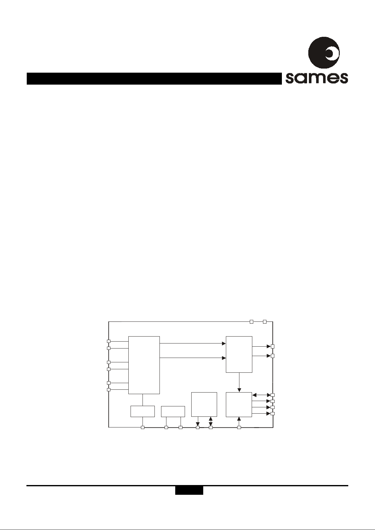
The SAMES SA9607P is a single-phase bidirectional energy
metering integrated circuit. It provides a cost effective solution
for energy meters with electro-mechanical displays, such as
stepper motors and impulse counters.
Two current sensor inputs allow the measurement of energy
consumption on both the live and neutral lines.
Direction detection of energy flow as well as other common
tamper conditions are flagged.
The power consumption on both the live and neutral are
continuously measured and the larger of the two is selected
for energy metering.
The SA9607P drives the calibration LED and the
electromechanical counter directly.
The SA9607P does not require any external trim-pots. All
required calibration and configuration data is read from a
small external EEPROM.
The SA9607P integrated circuit is available in 20 pin dual-inline plastic (DIP-20) and small outline (SOIC-20) package
types.
Figure 1: Block Diagram
1/12
Page 2

SA9607P
http://www.sames.co.za.
2/12
ELECTRICAL CHARACTERISTICS
(VDD = 2.5V, VSS = -2.5V, over the temperature range -10°C to +70°C#, unless otherwise specified.)
Parameter Symbol Min Typ Max Unit Condition
Operating temp. range T
o
-25 +85 °C
Supply Voltage: Positive V
DD
2.25 2.75 V
Supply Voltage: Negative V
SS
-2.75 -2.25 V
Supply Current: Positive I
DD
56 mA
Supply Current: Negative I
SS
56 mA
Current Sensor Inputs (Differential)
Input Current Range I
II
-25 +25 µA Peak value
Voltage Sensor Input (Asymmetrical)
Input Current Range I
IV
-25 +25 µA Peak value
Pin CNF
Input High Voltage V
IH
VDD-1 V
Input Low Voltage V
IL
VSS+1 V
Pin MOP, MON, LED, SCL
Output High Voltage V
OH
VDD-1 V IOH = -2mA
Output Low Voltage V
OL
VSS+1 V IOL = 5mA
Pin SEL1, ELT, SDA, DIRO Bi-direct
Input High Voltage V
IH
VDD-1 V
Input Low Voltage V
IL
VSS+1 V
Pin VREF With R = 24kΩ
Ref. Current -I
R
45 50 55 µA connected to V
SS
Ref. Voltage V
R
1.1 1 . 3 V Referred to V
SS
Oscillator Recommended crystal:TV colour burst crystal f = 3.5795 MHz
#
Extended Operating Temperature Range available on request.
ABSOLUTE MAXIMUM RATINGS*
Parameter Symbol Min Max Unit
Supply Voltage V
DD
-V
SS
-0.3 6.0 V
Current on any pin I
PIN
-150 +150 mA
Storage Temperature T
STG
-40 +125 °C
Operating Temperature T
O
-25 +85 °C
*Stresses above those listed under “Absolute Maximum Ratings” may cause permanent damage to the device. This is a stress
rating only. Functional operation of the device at these or any other condition above those indicated in the operational sections
of this specification, is not implied. Exposure to Absolute Maximum Ratings for extended periods may affect device reliability.
Page 3

SA9607P
http://www.sames.co.za.
3/12
Figure 2: Pin connections: Package: Dip-20, SOIC-20
DR-0155 7
1IIN 1 GND
SEL1
IIP1 IVP
CNF
IIN 2 DIRO
VSS
IIP2
VREF
SCL
SDA
VDD
ELT
LED
MOP
OSC 2OSC 1
MON
2
3
4
5
615
14
13
12
11
10
9
8
7
16
17
18
19
20
ORDERING INFORMATION
Part Number Package
SA9607PPA DIP-20
SA9607PSA SOIC-20
PIN DESCRIPTION
PIN
20
8
14
19
1, 2
3, 4
5
6
7
9, 12
13
15
16
17
18
10, 11
Description
Analog Ground. The voltage to this pin should be mid-way between V
DD
and VSS.
Positive supply voltage. The voltage to this pin is typically +2.5V if a shunt resistor is used for current sensing
or in the case of a current transformer a +5V supply can be applied.
Negative Supply Voltage. The voltage to this pin is typical -2.5V if a shunt resistor is used for current sensing
or in the case of a current transformer a 0V supply can be applied.
The current into the A/D converter should be set at 14µA
RMS
at nominal mains voltage. The voltage sense
input saturates at an input current of ±25µA peak.
Inputs for current sensor - channel 1 and Channel 2. The shunt resistor voltage from each channel is
converted to a current of 16µA
RMS
at rated conditions. The current sense input saturates at an input current
of ±25µA peak.
This pin provides the connection for the reference current setting resistor. A 24kΩ resistor connected to V
SS
set the optimum operating condition.
Serial clock output. This output is used to strobe data from the external EEPROM.
Serial data. Send and receive data from an external EEPROM.
Motor pulse outputs. These outputs can be used to drive an impulse counter or stepper motor directly.
Calibration LED output. Refer to section Led Output (LED) for the pulse rate output options.
Configure / Test input. For normal operation this pin must be connected to V
SS.
Current channel select output. This output indicates which channel is been used for kWh metering.
Earth loop tamper output. This output indicates an earth loop tamper condition.
Direction output. This output indicates the energy flow direction.
Connections for a crystal or ceramic resonator. (OSC1 = input; OSC2 = Output)
Designation
GND
V
DD
V
SS
IVP
IIN1, IIP1
IIN2, IIP2
VREF
SCL
SDA
MON, MOP
LED
CNF
SEL1
ELT
DIRO
OSC1, OSC2
Page 4
SA9607P
http://www.sames.co.za.
4/12
FUNCTIONAL DESCRIPTION
The SA9607P is a CMOS mixed signal analog/digital integrated
circuit, which performs power/energy calculations across a
power range of 1000:1, to an overall accuracy of better than
Class 1.
The integrated circuit includes all the required functions for
single phase power and energy measurement such as
oversampling A/D converters for the voltage and current
sense inputs, power calculation and energy integration. Internal
offsets are eliminated through the use of cancellation
procedures. The SA9607P incorporates an anti-tamper scheme
by continuously measuring the power consumption on both
LIVE and NEUTRAL lines. A fault is indicated when these
measurements differ by more than 12.5%. The SA9607P
generates pulses with a frequency proportional to the larger of
the two current measurements. The source (LIVE or NEUTRAL)
for these pulses is indicated on the SEL1 pin.
Various pulse outputs (MOP, MON and LED) are available.
The pulse rate on these pins follows the active power
consumption measured.
A low voltage stepper may be driven directly from the device
by connecting it between the MOP and MON pins, alternatively
an impulse counter may be driven directly by connecting it
between MOP and V
SS
.
The SA9607P configures itself from an external low cost
EEPROM that contain all meter configurations and calibration
data. No external trimming is required for this device. Calibration
of the device may be fully automated.
POWER CALCULATION
In Figure 7, the voltage drop across the current transformers
terminating resistor will be between 0 and 16mV
RMS
. These
voltages are converted to currents for each current sense
input, by means of resistors R
1
and R2 (channel 1) as well as
R
3
and R
4.
(channel 2).
The current sense input saturates at an input current of ±25µA
peak. The mains voltage (230VAC) is divided down through a
divider to 14V
RMS
. The current into the A/D converter input is
set at 14µA
RMS
at nominal mains voltage, via resistor R6 (1MΩ).
See Device Configuration for more details on the processing
of measured energy to frequency outputs.
ANALOG INPUT CONFIGURATION
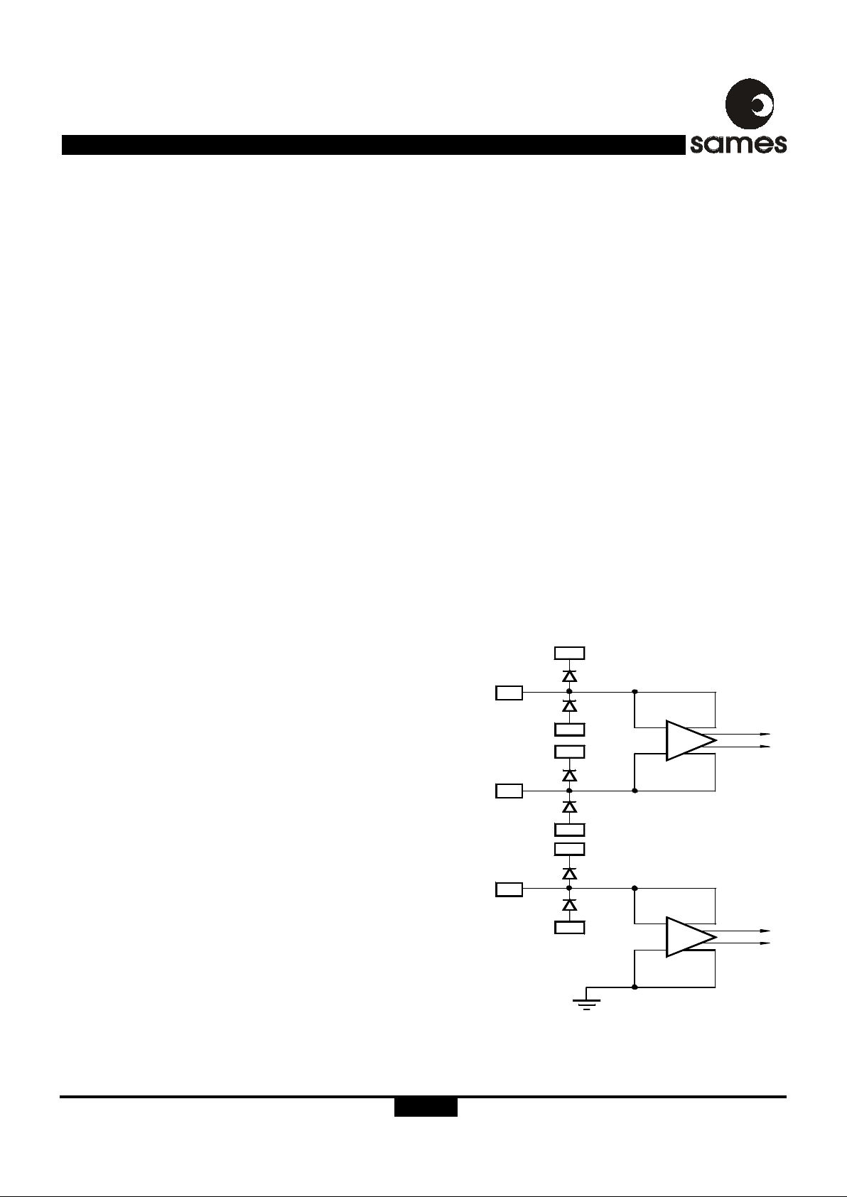
The input circuitry of the current and voltage sensor inputs are
illustrated in figure 3. These inputs are protected against
electrostatic discharge through clamping diodes.
The feedback loops from the outputs of the amplifiers A
I
and
A
V
generate virtual shorts on the signal inputs. Exact
duplications of the input currents are generated for the analog
signal processing circuitry.
AUTOMATIC DEVICE CONFIGURATION (BOOT UP)
During power up, registers containing configuration and
calibration information is updated from an external EEPROM.
The device itself never writes to the EEPROM so any write
protect features offered by manufacturer of EEPROM's may
be used to protect the configuration and calibration constants
of the meter. The device reloads its configuration every 1193
seconds from the external EEPROM in order to ensure correct
operation of the meter. Every data byte stored in the EEPROM
is protected with a checksum byte to ensure data integrity.
ELECTROSTATIC DISCHARGE (ESD)
PROTECTION
The SA9607P integrated circuit's input's/outputs are protected
against ESD.
POWER CONSUMPTION
The power consumption rating of the SA9607P integrated
circuit is less than 30mW.
VOLTAGE
SENSOR
INPUT
IVP
D
R-01288
SS
V
CURRENT
SENSOR
INPUTS
IIP
IIN
SS
V
V
DD
SS
V
V
DD
DD
V
GND
A
V
A
I
Figure 3: Analog Input Internal Configuration
Page 5
SA9607P
http://www.sames.co.za.
5/12
INPUT SIGNALS
VREF
The VREF pin is the reference for the bias resistor and is the
recommended point for analog calibration. With a bias resistor
of 24kΩ optimum conditions are set. Any changes to the bias
resistor will affect the output pulse rate quadratically (i.e.(R
= +5%,(f=10%).
Serial Data SDA
The SDA pin connects directly to the SDA pin of an external
EEPROM. The pin is used to transfer data between the
EEPROM to the SA9607P. An external pull up resistor in not
needed.
Serial Clock SCL
The SCL pin connects directly to the SCL of an external
EEPROM. The SCL output is used to strobe data at a rate of
50kHz out of the EEPROM. An external pull up resistor is not
needed.
Configuration CNF
A rising edge on the CNF pin, with DIRO high, will trigger a
register update from the external EEPROM. This feature may
be used during calibration to load updated register data in the
SA9607P. For normal operation of the SA9607P the CNF pin
should be connected to V
SS
.
OUTPUT SIGNALS
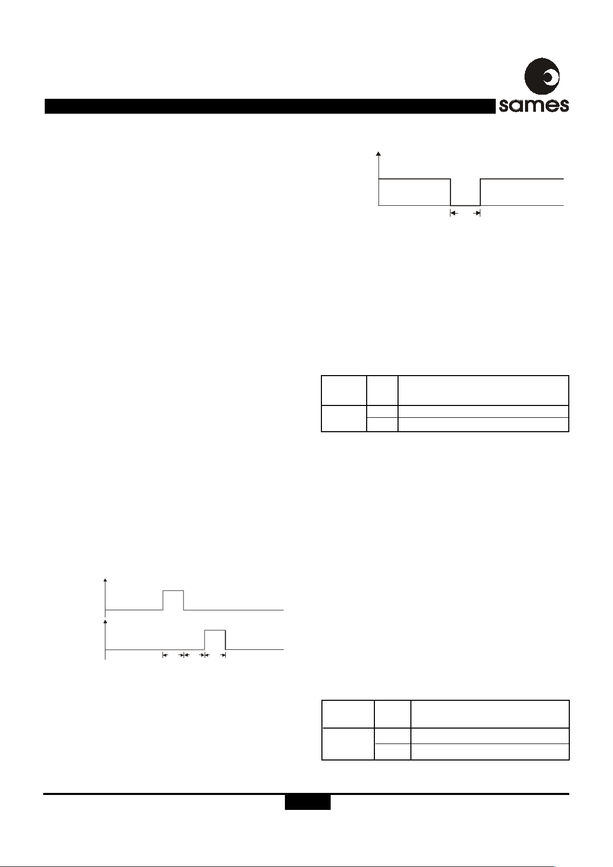
Motor output (MOP, MON)
The motor pulse width is programmable for 71ms and 142ms.
The MON pulse will follow the MOP pulse within the selected
pulse width time. This prevents that the motor armature is in
the wrong position after a power failure. Both MOP and MON
outputs are active high. One energy pulse is represented by a
MOP pulse followed by a MON pulse. The motor drive wave
forms are shown in figure 4.
LED output (LED)
Three options for the LED output pulse rate are available, 6400
and 3200 pulses per kWh, as well as a pulse rate of 1252
pulses per second at rated conditions. At 1252 pulses per
second t
LED
is 71µs, for the other options t
LED
is 10ms. The LED
output is active low as in figure 5.
tm = 71ms, 142ms
VDD
VDD
VSS
VSS
MONM
OP
t
m
tmt
m
DR-01559
Selected input indication (SEL1)
The SA9607P continuously compares the power consumptions
on both channel 1 and channel 2 inputs. The larger of the two
measurements are used for pulse output generation. The
SEL1 output pin indicates which channel is currently being
used for the pulse output.
Figure 5: LED pulse output
t
LED
= 10ms (6400 or 3200 pulses per kWh)
t
LED
= 71µs (1252 pulses per second)
VDD
VSS
LED
t
LED
DR -013 32
Earth loop tamper indication (ELT)
In case the power measurements from both current channels
differ by more than 12.5%, (indicating a earth loop tamper
condition), the ELT output is set to zero. The SA9607P
continues to generate output pulses from the larger of the two
measured powers in this condition. The ELT output is active
low.
Direction indication (DIRO)
The SA9607P provides information about the energy flow
direction on pin DIRO. A logic 1 on pin DIRO indicates reverse
energy flow. Reverse energy flow is
defined as the condition
where the voltage sense input and a current sense input are
out of phase (greater than 90 degrees).
Positive energy flow, when voltage sense and current sense
input are in phase, is indicated on pin DIRO as a logic 0.
The DIRO pin may be used to drive a LED in order to indicate
reverse energy.
Figure 4: Motor drive on MON and MOP pins of device
Signal
Output
Description
0
1
Current Channel 1 selected (IIN1 / IIP1)
Current Channel 2 selected (IIN2 / IIP2)
SEL1
Value
Signal
Output
Description
1
0
Reverse energy flow
Forward energy flow
DIRO
Value
Page 6
SA9607P
http://www.sames.co.za.
6/12
DEVICE CONFIGURATION
SIGNAL FLOW DESCRIPTION
The following is an overview of the SA9607P's registers. For
a detailed description of each parameter please refer to
parameter description section.
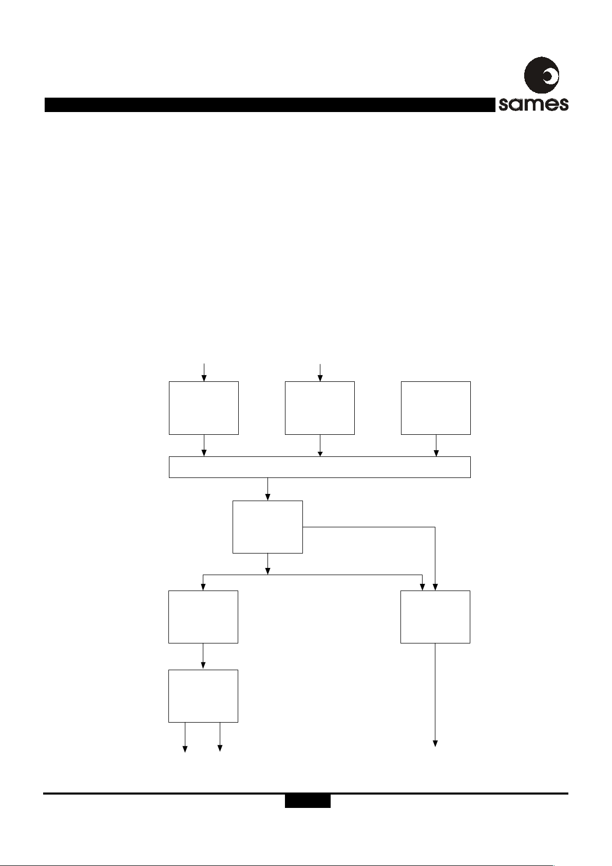
Figure 6 shows the various registers in the SA9607P's power
to pulse rate block. The inputs to this block are two single bit
pulse density modulated signals, each having a pulse rate of
641454 pulses per second at rated conditions. The parameters
Kc1, Kc2, Ne, Cs, Kr, Cres, and Cled contain values which are
read from the external EEPROM during power up.
The divider registers, Channel 1 Balance and Channel 2
Balance, are used for calibration and to balance the gain of
each channel. The Earth Leakage Compensation register is
used to compensate for any permissible earth leakage that
may cause the SA9607P to indicate a tamper condition at low
current. The Channel Select register selects the source (channel
1 or channel 2) which will be used for the pulse output. Register
Rated Condition is used to program the rated condition of the
meter and feeds the registers LED-constant and Counter
Resolution with the applicable pulse rate. These two registers
are programmed to select the LED output rate and the counter
resolution (pulses per kWh) respectively. The Counter Pulse
Width register is used to program the pulse width for the
mechanical counter driver output MOP and MON.
Figure 6: Signal flow block diagram
Channel 1
Balance
÷Kc1
Channel 2
Balance
÷Kc2
Earth Leakage
Compensation
Ne
Channel Select (1, 2, auto) Cs
Rated Condition
÷Kr
Counter
Resolution
Cres
Counter
Pulse width
CPW
LED-Constant
Cled
MOP MON
LED
Normally 6400p/kWh
Normally 1253p/s
Channel 1 Power
641454p/s
Channel 2 Power
641454p/s
Page 7

SA9607P
http://www.sames.co.za.
7/12
PARAMETER DESCRIPTION
Refer to the EEPROM memory allocation map as well as the
Signal flow diagram figure 6, for a description of the registers
used in this section.
EEPROM Memory Allocation
The following table shows the EEPROM memory allocation
as well as the corresponding name. The uneven byte always
contains a XORed byte of the previous even byte. This is the
checksum byte used by the SA9607P to ensure data integrity.
Channel Balance (KC)
Kc defines the dividing factor, which is applied to the incoming
pulse rate. This value is typically 511. This factor is used for
calibration meter and gain balancing of the 2 current channels.
The value for Kc is usually between 400 and 640.
Kc is made up of 2 bytes, D12 and D14 or D16 or D18 which
forms a 10 bit value.
KEY: (- = DON'T CARE); (V = VALUE/PARAMETER); (0,1 = LOGICAL VALUE); (X = BIT-XOR)
Rated Condition (KR)
Kr is used to program the rated condition of the meter. This
feature is required for a correct counter increment of meters
designed for different rated conditions using the same
integrated circuit. Rated conditions from less than 10A to
several 100A are possible.
The channel balance values should be used to compensate
for rounding errors in Kr. Kr is calculated as follows:
Kr =(1252 x 1000 x 3600)/(Rated volt x Rated current x 6400)-1
Kr is made up of 1 byte (D20)
Description E
2
Address Contents Bit [7:0] Name
Channel 1 Balance LSB 12 Kc1 vvvvvvvv D12
13 XOR of ADDR 12 xxxxxxxx
Channel 1 Balance MSB 14 Kc1
------vv
D14
15 XOR of ADDR 14 xxxxxxxx
Channel 2 Balance LSB 16 Kc2 vvvvvvvv D16
17 XOR of ADDR 16 xxxxxxxx
Channel 2 Balance MSB 18 Kc2
------vv
D18
19 XOR of ADDR 18 xxxxxxxx
Rated Condition 20 Kr vvvvvvvv D20
21 XOR of ADDR 22 xxxxxxxx
Led Pulse-rate 22 Cled
------vv
D22
23 XOR of ADDR 22 xxxxxxxx
Counter Pulse-width 24 Cpw
0v------
D24
Counter Resolution 24 Cres
------vv
25 XOR of ADDR 24 1xxxxxxx
Earth leak Compensation 26 Ne
------vv
D26
Channel Select Mode 26 Cs
----vv--
27 XOR of ADDR 24 xxxxxxxx
Page 8
SA9607P
http://www.sames.co.za.
8/12
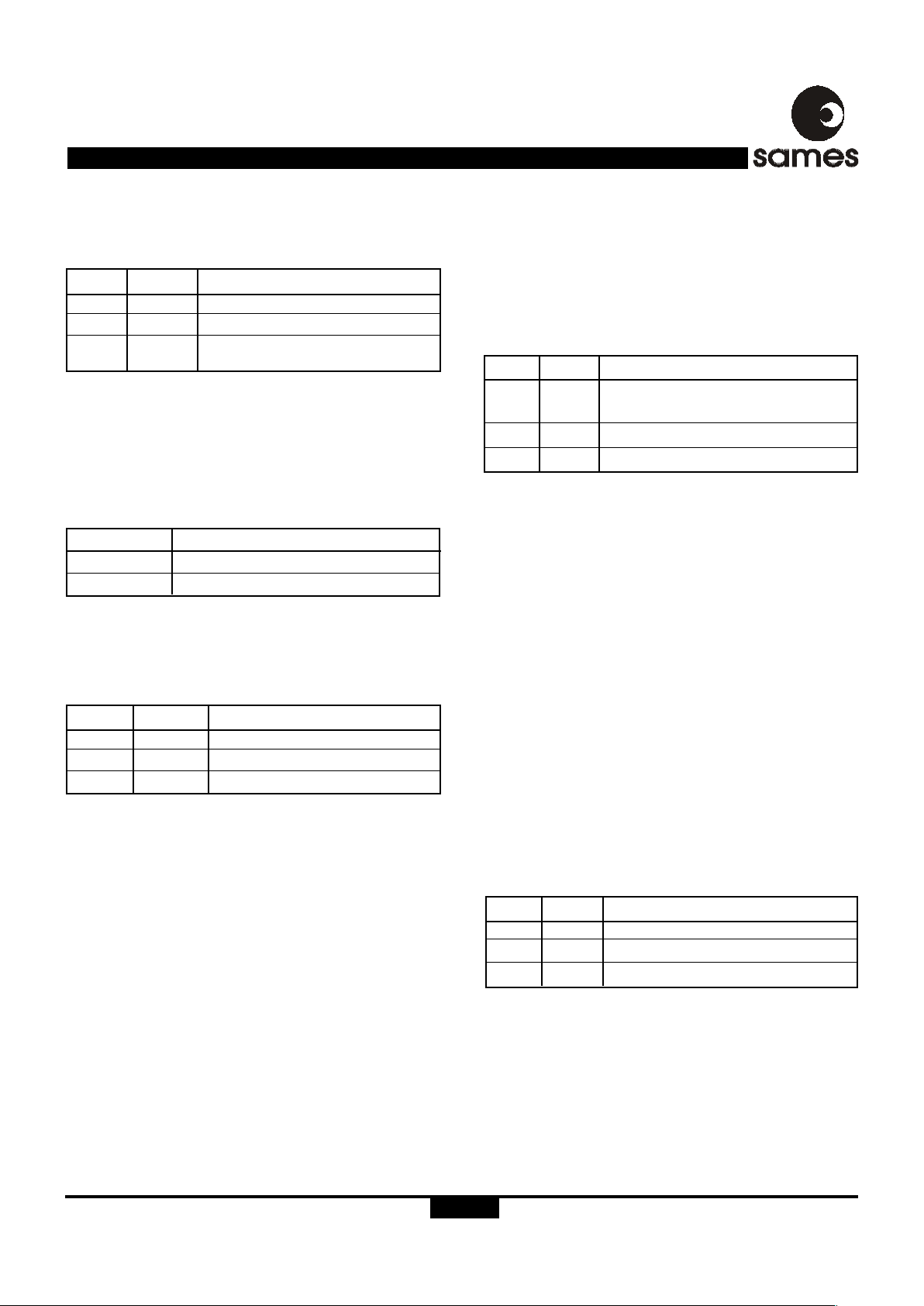
LED Pulse-rate (CLED)
Two bits of byte D22 allow for the selection of 3 different LED
Pulse-rates as follows.
Refer to LED output section for details on the LED pulse width.
Counter Pulse-Width (CPW)
The pulse width for the mechanical counter driver output is
selectable to accommodate various step-motor and impulsecounter requirements. Bit 6 from byte D24 selects the pulse
rate as follows:
Counter Resolution (CRES)
Bit 1 and 0 from byte D24 allow for the selection of 3 different
counter resolutions. Note that one energy pulse is represented
by a MOP pulse followed by a MON pulse.
D24[1] D24[0] Counter Resolution
0 0 1 p/KWh
1 0 10 p/KWh
- 1 100 p/KWh
Channel Select Mode (CS)
For calibration purposes, the source for the energy metering
may be selected from a specific channel. The ELT-indication
is not influenced, but the metering is taken from the selected
channel only. For normal operation, the channel select mode
is set to automatic mode so that the larger of the two channels
are used for energy measurement. Bits 3 and 2 of byte D26
sets the channel select mode as follows:
Earth Leak Compensation (NE)
Earth leakage in domestic wiring systems could result in
tamper detection at low current levels. The SA9607P caters
for these conditions, by taking possible earth leakage into
account when comparing the power consumption on live and
neutral.
The value for the permissible earth leakage is usually around
30mA. It has to be adjusted according to the rated meter
condition and allows for derivations from the 30mA value. The
actual value of the leak current can be calculated from the
following formula:
Ileak = Rated current x Ne
Ileak is the earth leakage current in mA used for correction.
This value is subtracted from the difference measured between
live and neutral power.
Ne is made up of bits 1 and 2 of byte D26 and can be set as
follows:
D24[6] Counter Pulse-Width
0 71ms
1 142 ms
D26[1] D26[0] Ne factor
0 0 0.15
0 1 0.076
1 - 0.032
D22[1] D22[0] Calibration LED - Output
0 0 6400 p/KWh
0 1 3200 p/KWh
1 - 1252 pulses/second @ rated for
fast calibration
D26[3] D26[2] Metering Source
- 0 Automatic, channel 1 or 2 whichever
shows higher consumption
1 1 Channel 1
0 1 Channel 2
Page 9
SA9607P
http://www.sames.co.za.
9/12
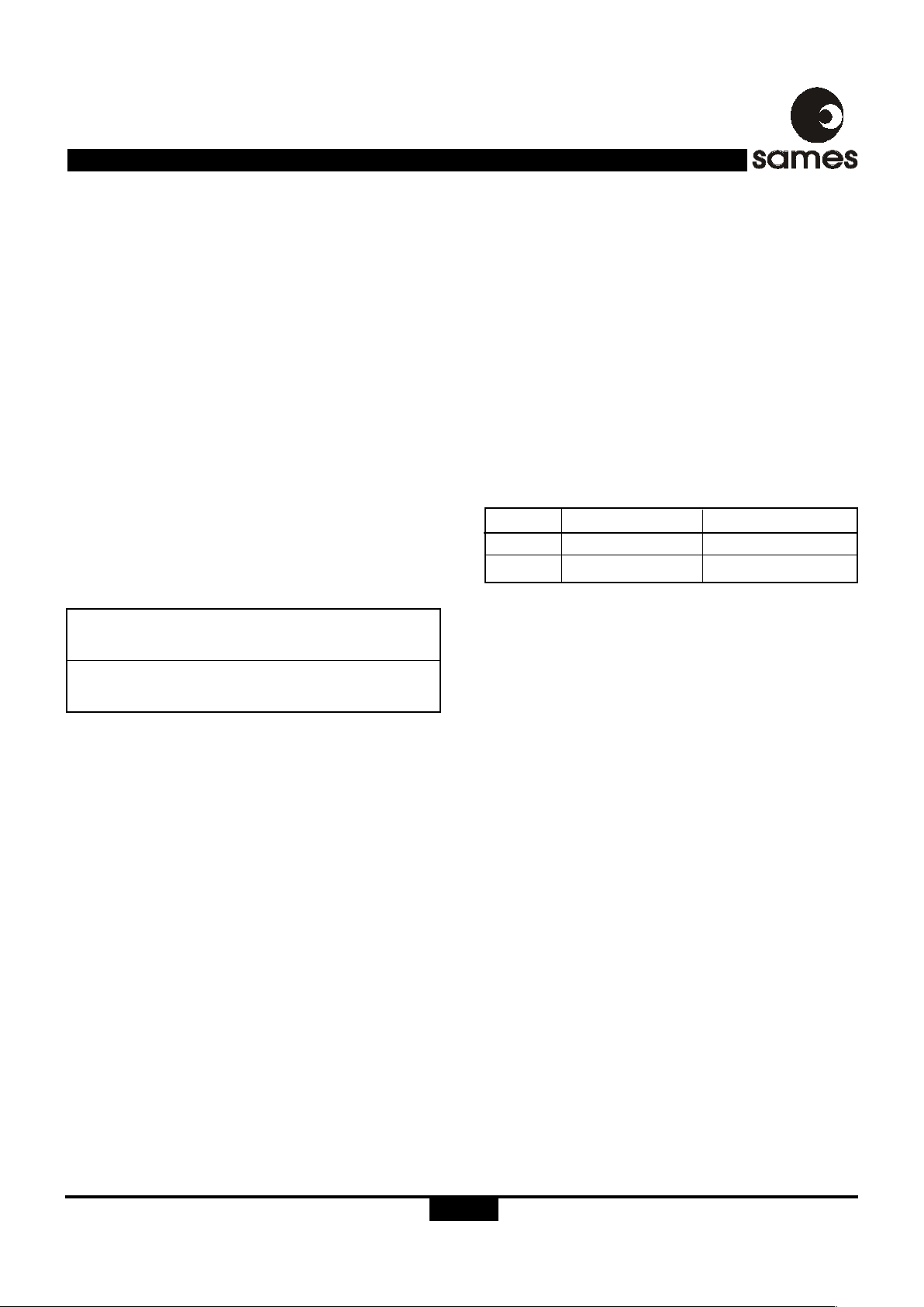
TYPICAL APPLICATION
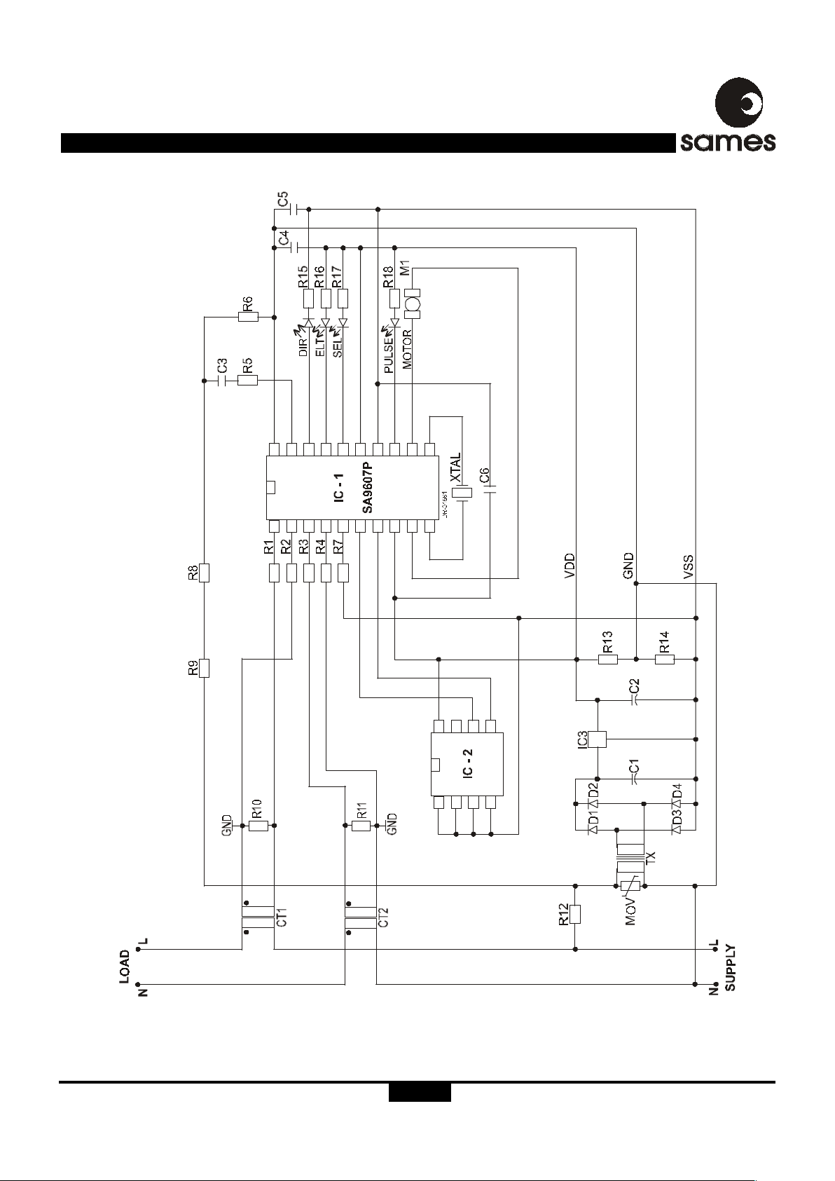
In Figure 7, the components required for a stand-alone power
metering application, is shown. Application modules as well as
application notes for the SA9607P and SA9607M Integrated
Circuits are available on request.
Two current transformers are used for mains current sensing.
The current channel showing the highest power consumption
will be selected by the SA9607P for energy metering.
The most important external components for the SA9607P
integrated circuit are the current sense resistors, the voltage
sense resistors as well as the bias setting resistor.
CURRENT SENSE RESISTORS
The resistors R1, R2, R3 and R4 define the current level into
the current sense inputs of the device. The components
should be selected for input currents of 16µA
RMS
into the
current channels of the SA9607P at I
MAX
(rated current of the
meter). The voltage drop on the shunt termination resistors
R
10
and R17 should be at least 20mV.
Where:
IL = Line current/CT-ratio
R10 = Termination resistor
R11 = Termination resistor
Voltage Sense Resistors
R9, R8, R6 and R5 set the current for the voltage sense input.
The values should be selected so that the input current into the
voltage sense input (virtual ground) is set to 14µA
RMS
. A
capacitor is used to compensate for a phase shift introduced
by the CTs.
Bias Resistor
R
7
defines all on-chip bias and reference currents. With R7 =
24kΩ, optimum conditions are set.
Any change to R
7
will affect the output quadratically.
Compatible EEPROM Devices
The following devices were tested and found functional with
the SA9607P.
Current Channel 1
R1= R2= (IL/16µA
RMS
) x R10/2
Current Channel 2
R
3
= R4= (IL/16µA
RMS
) x R11/2
Please see various manufactures datasheets on programming
and using IIC memory devices.
Software for programming the EEPROM devices is available
from SAMES website.
Devices Manufacturer WEB Site
AT24C01A Atmel http://www.atmel.com
24C01 STMicro electronics http://www.st.com
Page 10
SA9607P
http://www.sames.co.za.
10/12
Figure 7: Application Circuit
Page 11

SA9607P
http://www.sames.co.za.
11/12
Note 1: Resistor (R1, R2, R3 and R4) values are dependant upon the selected value of R10 and R11.
Note 2: See TYPICAL APPLICATION when selecting the value of R10 and R11.
Note 3: Capacitor (C6) to be positioned as closed to Supply Pins (V
DD
& VSS) of IC-1, as possible.
Note 4: Capacitor (C3) selected to minimize phase error introduced by current transformer (typically 1.5µF for normal CTs.)
Parts List for Application Circuit: Figure 7
Item Symbol Description Detail
1 IC1 SA9607P DIP-20/SOIC-20
2 IC2 AT24C01, or eqivalent device
3 D1 Diode, Silicon 1N4007
4 D2 Diode, Silicon 1N4007
5 D3 Diode, Silicon 1N4007
6 D4 Diode, Silicon 1N4007
7 D5 Light emmitting diode, Red
8 D6 Light emmitting diode, Green
9 D7 Light emmitting diode, Amber
10 D8 Light emmitting diode, Green
11 XTAL Crystal, 3.5759MHz
12 R1 Resistor, 1/4W, 1%, metal Note 1
13 R2 Resistor, 1/4W, 1%, metal Note 1
14 R3 Resistor, 1/4W, 1%, metal Note 1
15 R4 Resistor, 1/4W, 1%, metal Note 1
16 R5 Resistor, 1M, 1/4W, 1%, metal
17 R6 Resistor, 24k, 1/4W, 1%, metal
18 R7 Resistor, 22k, 1/4W, 1%, metal
19 R8 Resistor, 180k, 1/4W, 1%, metal
20 R9 Resistor, 200k, 1/4W, 1%, metal
21 R10 Resistor, 1/4W, 1%, metal Note 2
22 R11 Resistor, 1/4W, 1%, metal Note 2
23 R12 Resistor, 10Ω, 2W, Wire wound
24 R13 Resistor, 1k, 1/4W, 1%, metal
25 R14 Resistor, 1k, 1/4W, 1%, metal
26 R15 Resistor, 1k, 1/4W, 5%, carbon
27 R16 Resistor, 1k, 1/4W, 5%, carbon
28 R17 Resistor, 1k, 1/4W, 5%, carbon
29 R18 Resistor, 1k, 1/4W, 5%, carbon
30 C1 Capacitor, 2200µF, 16V, electrolytic
31 C2 Capacitor, 100µF, 16V, electrolytic
32 C3 Capacitor Note 4
33 C4 Capacitor, 220nF
34 C5 Capacitor, 220nF
35 C6 Capacitor, 820nF Note 3
36 CT1 Current Transformer
37 CT2 Current Transformer
38 TX Transformer, 230V/9V
39 IC3 78LC05, Voltage regulator
40 M 1 Bipolar step motor
41 M0V 400V, Metal oxide varistor
Page 12

SA9607P
http://www.sames.co.za.
12/12
Any Sales or technical questions may be posted to our e-mail address below:
For the latest updates on datasheets, please visit our web site:
http://www.sames.co.za.
SOUTH AFRICAN MICRO-ELECTRONIC SYSTEMS (PTY) LTD
Tel: (012) 333-6021
Tel: Int +27 12 333-6021
Fax: (012) 333-8071
Fax: Int +27 12 333-807
1
DISCLAIMER:
The information contained in this document is confidential and proprietary to South African Micro-Electronic Systems (Pty) Ltd
("SAMES") and may not be copied or disclosed to a third party, in whole or in part, without the express written consent of SAMES.
The information contained herein is current as of the date of publication; however, delivery of this document shall not under any
circumstances create any implication that the information contained herein is correct as of any time subsequent to such date.
SAMES does not undertake to inform any recipient of this document of any changes in the information contained herein, and SAMES
expressly reserves the right to make changes in such information, without notification, even if such changes would render
information contained herein inaccurate or incomplete. SAMES makes no representation or warranty that any circuit designed by
reference to the information contained herein, will function without errors and as intended by the designer.
P O Box 15888
33 Eland Street
Lynn East 0039
Republic of South Africa
33 Eland Street
Koedoespoort Industrial Area
Pretoria
Republic of South Africa
 Loading...