

Page 1
Vector Modulator, 1.94 to 2.24 GHz
V 4.00
SA90-0001
Features
n Operates 1.94 to 2.24 GHz
n Chip Scale Package.
n Low Amplitude Ripple
n Linear Phase
n 50 Ohm nominal impedance
n Continuously Variable Across a Full 360 degree range
n Test Boards to be Available
Description
M/A-COM's SA90-0001 is a Vector Modulator that significantly reduces the required board space compared to hybrid
solutions. The monolithic passive elements will lead to
greater repeatability lot-to-lot. Low amplitude ripple will
provide superior performance. High intercept and compression points will contribute to more linear system performance. SA90-0001 is ideally suited for wireless infrastructure applications.
M/A-COM’s MADRCC0002 Dual Linearizer is designed
to simplify the control of Vector Modulators. See
Figure 1 and App Note AN3001.
Electrical Specifications TA = +25°
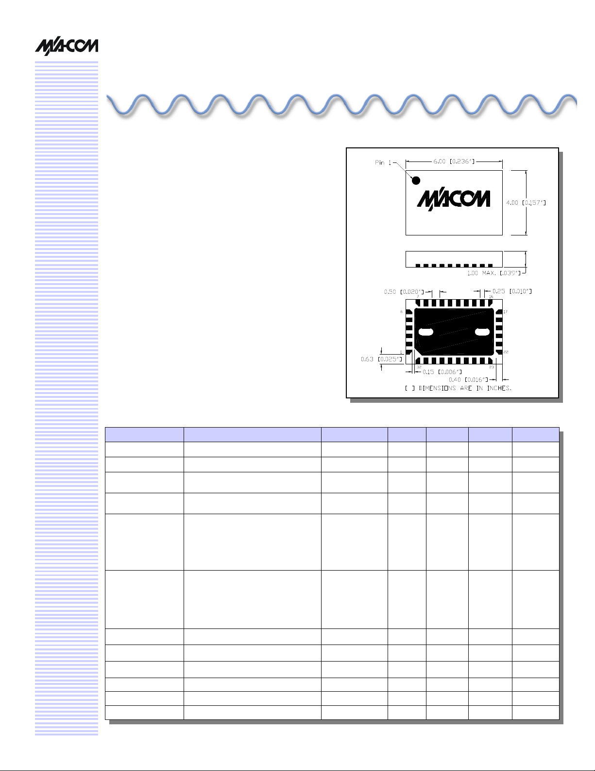
CSP-6
Parameter Test Conditions Frequency Units Min Typical Max
Impedance — — O — 50 —
Reference Loss Z = 50O 1.94—2.34 GHz dB -13.5 — -10.0
Attenuation Range Z = 50O
Phase Shift Range Z = 50O, Over minimum
Amplitude Ripple
Deviation from Lin-
ear Phase
Return Loss Over 10 dB Attenuation Range 2.04—2.24 GHz dB 15 — —
Input IP3 Over 10 dB Attenuation Range 2.04—2.24 GHz dBm — +41 —
Input P
Noise Figure Over 10 dB Attenuation Range 2.04—2.24 GHz dB — — Note 1
Switching Speed 50% Control to 10%/90% RF — ns — 500 —
I Supply — — mA — — 100
Over 10 dB Attenuation Range 2.04—2.24 GHz dBm — +29 —
1dB
Above Reference Loss
Attenuation Range
Z = 50O, Ref Loss
Z = 50O, 5 dB above Ref Loss
Z = 50O, 10 dB above Ref Loss
Z = 50O, Ref Loss
Z = 50O, 5 dB above Ref Loss
Z = 50O, 10 dB above Ref Loss
Z = 50O, Ref Loss
Z = 50O, 5 dB above Ref Loss
Z = 50O, 10 dB above Ref Loss
Z = 50O, Ref Loss
Z = 50O, 5 dB above Ref Loss
Z = 50O, 10 dB above Ref Loss
1.94—2.34 GHz dB 10 — —
1.94—2.34 GHz deg 0 — 360
2.08—2.20 GHz
2.08—2.20 GHz
2.08—2.20 GHz
2.04—2.24 GHz
2.04—2.24 GHz
2.04—2.24 GHz
2.08—2.20 GHz
2.08—2.20 GHz
2.08—2.20 GHz
2.04—2.24 GHz
2.04—2.24 GHz
2.04—2.24 GHz
dB
dB
dB
dB
dB
dB
deg
deg
deg
deg
deg
deg
—
—
—
—
—
—
—
—
—
—
—
—
—
—
—
—
—
—
—
—
—
—
—
—
±0.25
±0.35
±0.2
±0.3
±0.4
±0.5
±0.5
±1.0
±1.5
±1.0
±1.5
±2.0
1. Noise figure is approximately equal to the absolute attenuation.
Page 2
Vector Modulator, 1.94 to 2.24 GHz
SA90-0001
V 4.00
Absolute Maximum Ratings
Parameter Absolute Maximum
Max. Input Power
1.5 t6 2.0 GHz
Other Frequencies
DC Voltages
DC Current 50 mA Max per Bias
Operating Temperature -40°C to +85°C
Storage Temperature -65°C to +125°C
2. Operation of this device above any one of these parameters
may cause permanent damange.
3. Note that external dropping resistors are required to limit the
current and voltage on the PIN diodes.
3
Vbias1 or Vbasis2
2
+34 dBm
+24 dBm
+1.0V
Pad Configuration
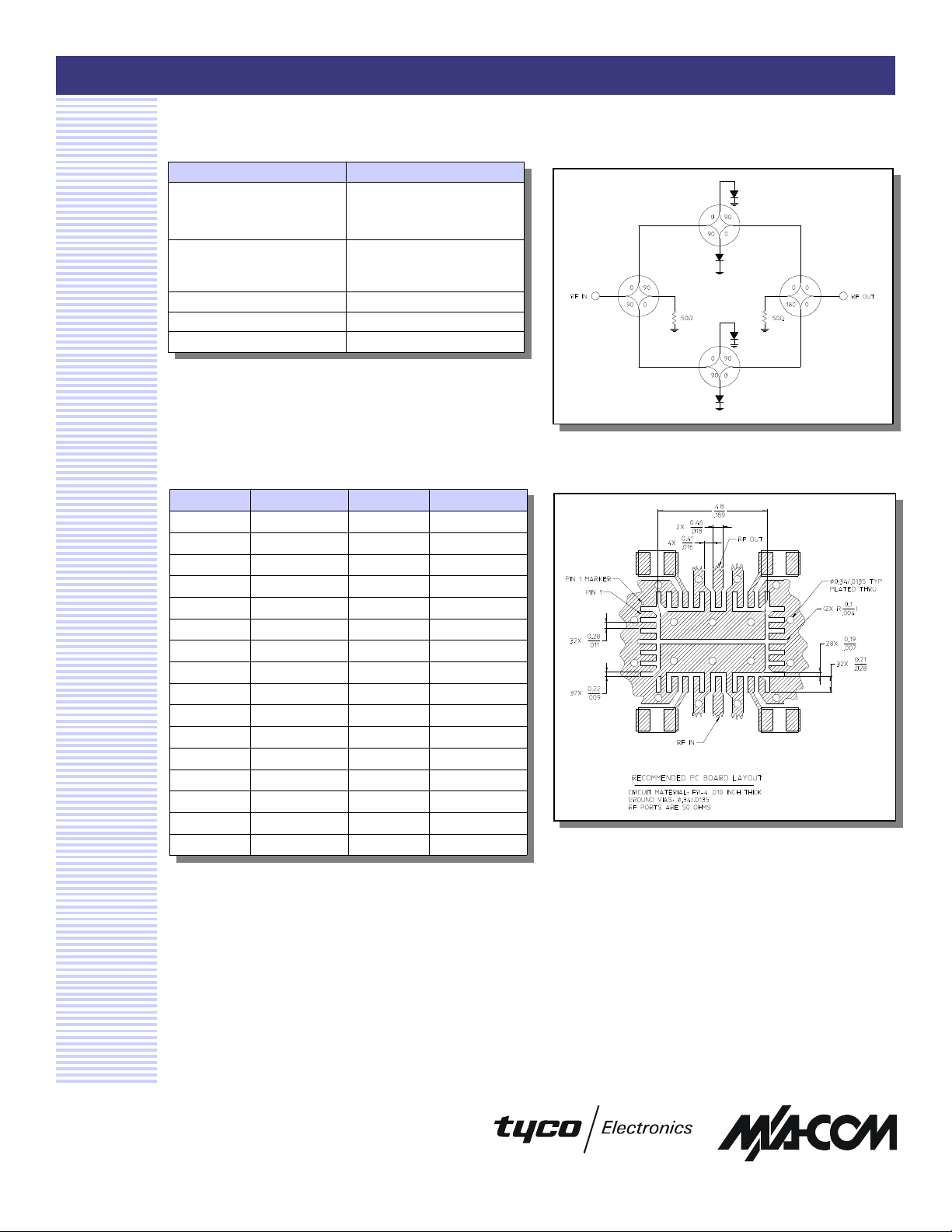
Pin # Function Pin # Function
1 NC 17 NC
2 NC 18 NC
3 NC 19 NC
4 NC 20 NC
5 NC 21 NC
6 NC 22 NC
7 NC 23 NC
8 NC 24 Bias 2B
9 Bias 1A 25 NC
10 NC 26 GND
11 GND 27 RF OUT
12 RF IN 28 GND
13 GND 29 NC
14 NC 30 Bias 1B
15 Bias 2A 31 NC
16 NC 32 NC
Schematic
Recommended PCB Layout
Specifications subject to change without notice.
n North America: Tel. (800) 366-2266
n Asia/Pacific: Tel.+81-44-844-8296, Fax +81-44-844-8298
n Europe: Tel. +44 (1344) 869 595, Fax+44 (1344) 300 020
Visit www.macom.com for additional data sheets and product information.
2
Page 3
Vector Modulator, 1.94 to 2.24 GHz
1.5V
2.0V
3.5V
3.5V
90°
0°
bias 2 = 0V
bias 2 = +5V
90°
0°
bias 2 = +5V
bias 2 = 0V
coefficient = 0.5
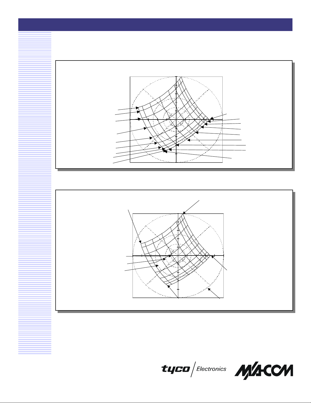
Figure 1A - Phase and Attenuation of SA90-0001, Vector Modulator Linearized with
SA90-0001
V 4.00
MADRCC0002 Dual Linearizer
(y)
45°
bias 1 = 0.0V
0.5V
1.0V
2.5V
3.0V
bias 1 = 5.0V
Loss = 22 dB
Loss = 17 dB
Loss = 12 dB
bias 1 = 0V
Figure 1B
(y)
bias 1 = 0V
45°
bias 2 = 5.0V
bias 2 = 0.0V
(x)
bias 1 = +5V
3.0V
2.5V
2.0V
(x)
1.5V
1.0V
0.5V
4. Tic marks on x,y axes refer to reflection coefficient in increments of 0.1V. Reflection coefficients vary from -0.5 to +0.5 on both
the x and y axes.
5. Data is for vector modulators driven by linearizers per attached schematic.
6. Inputs to the linearizers vary from 0 to 5V.
7. The phase with the inputs to both linearizers set to +5V is arbitrarily called zero degrees.
Specifications subject to change without notice.
n North America: Tel. (800) 366-2266
n Asia/Pacific: Tel.+81-44-844-8296, Fax +81-44-844-8298
n Europe: Tel. +44 (1344) 869 595, Fax+44 (1344) 300 020
Visit www.macom.com for additional data sheets and product information.
bias 1 = +5V
Reflection
Page 4
Vector Modulator, 1.94 to 2.24 GHz
bias 1 = 0 µA
4 µA
9 µA
17 µA
33 µA
62 µA
112 µA
205 µA
690 µA
mA
mA
mA
bias 2 = 15
mA
mA
mA
690 µA
205 µA
112 µA
62 µA
33 µA
17 µA
9 µA
4 µA
0 µA
90°
0°
bias 2 = 0 µA
bias 2 = 0 µA
bias 2 = 15
mA
bias 2 = 15
mA
90°
0°
coefficient = 0.5
coefficient = 0.6
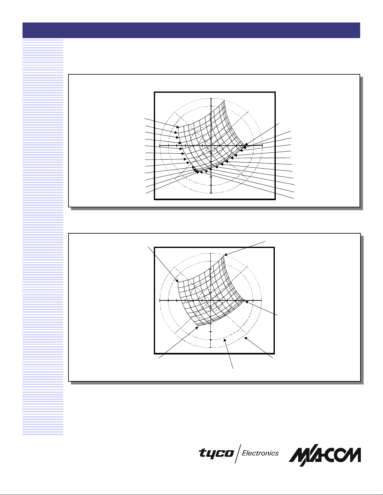
Figure 2A - Phase and Attenuation of SA90-0001 vs. Bias Current
2.3
6.7
15
SA90-0001
V 4.00
(y)
45°
6.7
2.3
(x)
Figure 2B
bias 1 = 0 µA
bias 1 = 15 mA
(y)
Reflection
8. Tic marks on x,y axes refer to reflection coefficient in increments of 0.1. Reflection coefficients vary from -0.6 to +0.6 on both
the x and y axes.
9. The phase with the inputs to both linearizers set to +15mA is arbitrarily called zero degrees.
bias 1 = 0 µA
45°
(x)
bias 1 = 15 mA
Reflection
Specifications subject to change without notice.
n North America: Tel. (800) 366-2266
n Asia/Pacific: Tel.+81-44-844-8296, Fax +81-44-844-8298
n Europe: Tel. +44 (1344) 869 595, Fax+44 (1344) 300 020
Visit www.macom.com for additional data sheets and product information.
Page 5
Vector Modulator, 1.94 to 2.24 GHz
SA90-0001
V 4.00
Ordering Information
Part Number Package
SA90-0001 Bulk Packaging
SA90-0001TR Tape and Reel
SA90-0001-DC000 Units Mounted on Test Board with
Driver
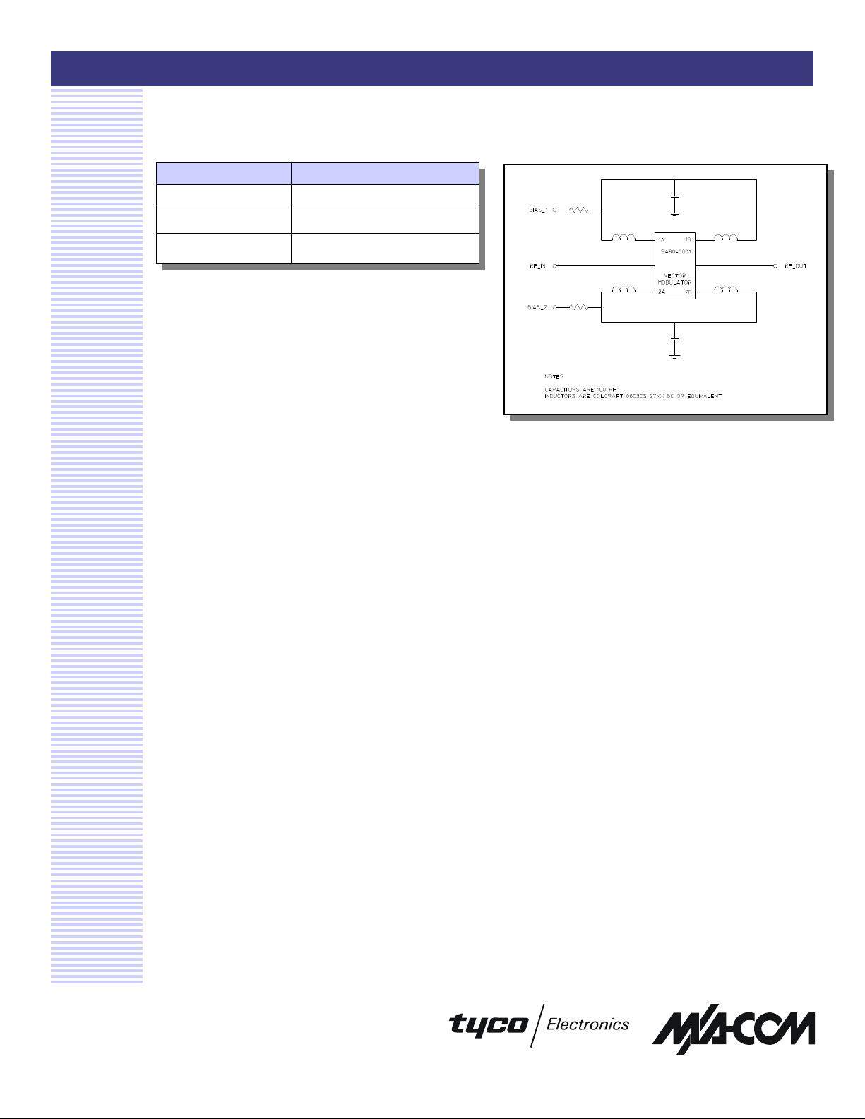
Functional Block Diagram
Specifications subject to change without notice.
n North America: Tel. (800) 366-2266
n Asia/Pacific: Tel.+81-44-844-8296, Fax +81-44-844-8298
n Europe: Tel. +44 (1344) 869 595, Fax+44 (1344) 300 020
Visit www.macom.com for additional data sheets and product information.
5
 Loading...