

Page 1

INTEGRATED CIRCUITS
SA5775A
Differential air core meter driver
Product specification
Supersedes data of 1997 Feb 24
1999 Sep 20
Page 2

Philips Semiconductors Product specification
SA5775ADifferential air-core meter driver
DESCRIPTION
The SA5775A is a monolithic driver for controlling air-core (or
differential) meters typically used in automotive instrument cluster
applications. The circuit interfaces with a microprocessor through a
serial bus and directly drives the air-core meter. The SA5775A has
10-bit resolution (0.35 degree) and is guaranteed to be monotonic.
Data can be shifted through the part, allowing several SA5775As to
be cascaded with only one chip-select line. On-chip current shut
down logic protects the circuit from external faults.
FEATURES
•10-Bit resolution (0.35 degrees)
•Exceptional accuracy (0.25 degrees, typical)
•High-torque capability
•Active differential drivers eliminate back-EMF issues
•No RFI/EMI generation issues
•Simple serial interface
•Simple cascading capability for multiple meters
•Internal fault protection
•Only one external component required (bypass capacitor)
APPLICATION
•Instrumentation utilizing air-core meters
PIN CONFIGURATION
1
SIN-
SIN+
2
A
3
GND
4
V
IGN
DATA
DATA
DATA
5
OUT
6
IN
V
7
CC
89
OE
SIN-
1
2
SIN+
3
NC
NC
4
5
NC
6
A
GND
7
V
IGN
8
OUT
9
DATA
IN
10
NC
NC NC
11
12
NC NC
13
V
CC
OE
14
Figure 1. Pin configuration
N Package
D Package
16
COS+
15
COS-
A
14
GND
13
D
GND
12
nc
11
ST
10
CS
S
CLK
COS+
28
27
COS-
NC
26
25
NC
24
NC
23
A
GND
NC
22
NC
21
20
D
GND
19
ST
18
17
16
CS
15
S
CLK
SL00453
ORDERING INFORMATION
DESCRIPTION TEMPERATURE RANGE ORDER CODE DWG #
16-Pin Plastic Dual In-Line Package (DIP)
28-Pin Small Outline Package (SO)
1999 Sep 20 853-1929 022369
2
-40 to +85°C
-40 to +85°C
SA5775AN SOT38-4
SA5775AD SOT136-1
Page 3
Philips Semiconductors Product specification
SA5775ADifferential air-core meter driver
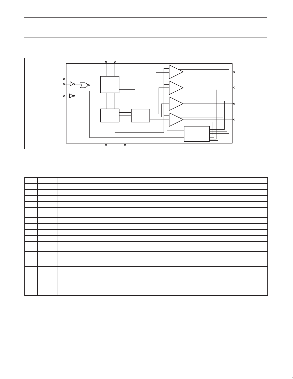
BLOCK DIAGRAM
4576 3
2
8
9
10
LOGIC
3
1
16
DAC MUX
11
12 13 14
SHUT–DOWN
LOGIC
15
SL00454
Figure 2. Block diagram
Table 1. SA5775A Pin Descriptions for the N Package (Dual In-Line)
Pin # Name Function
1. SIN– Negative output connection to the SIN coil of the gauge.
2. SIN+ Positive output connection to the SIN coil of the gauge.
3. A
4. V
5. DATA
6. DATAINSerial data input. A new data word is serially shifted into the part on the rising edge of S
7. V
8. OE Output drivers are turned off when this input is low. Current draw is minimized.
9. S
10. CS Active high chip select input. When CS is high, the part is enabled to receive a new serial input word. The high-to-low tran-
11. ST Status output from this IC to indicate that the outputs have been disabled. The outputs may be disabled due to shorted out-
12. nc Not connected
13. D
14. A
15. COS– Negative output connection to the COS coil of the gauge.
16. COS+ Positive output connection to the COS coil of the gauge.
Ground for V
GND
Analog supply. Nominally 14.0 V.
BB
Serial data output. Output of the internal shift register. When a new data word is shifted in, the old word is shifted out the
OUT
DATA
OUT
5 V logic supply. The internal latches and registers are set to zero on the rising edge of this signal.
CC
Serial clock input. Data is loaded into the part on the rising edge of S
CLK
supply. Pins 3, 13 and 14 connected on the circuit board.
IGN
pin.
CLK
. The data is shifted in MSB first.
CLK
.
sition of CS loads the new 10-bit word into the DAC registers and updates the output.
puts, over temperature conditions, power up reset, or output enable control pin .This output is an open drain output .Multiple
status outputs may be wire OR’ed together .This output is low when the outputs are disabled due to a fault condition.
Ground for VCC supply. Connect to Pins 3 and 14.
GND
Ground for VBB supply. Connect to Pins 3 and 13.
GND
1999 Sep 20
3
Page 4
Philips Semiconductors Product specification
SA5775ADifferential air-core meter driver
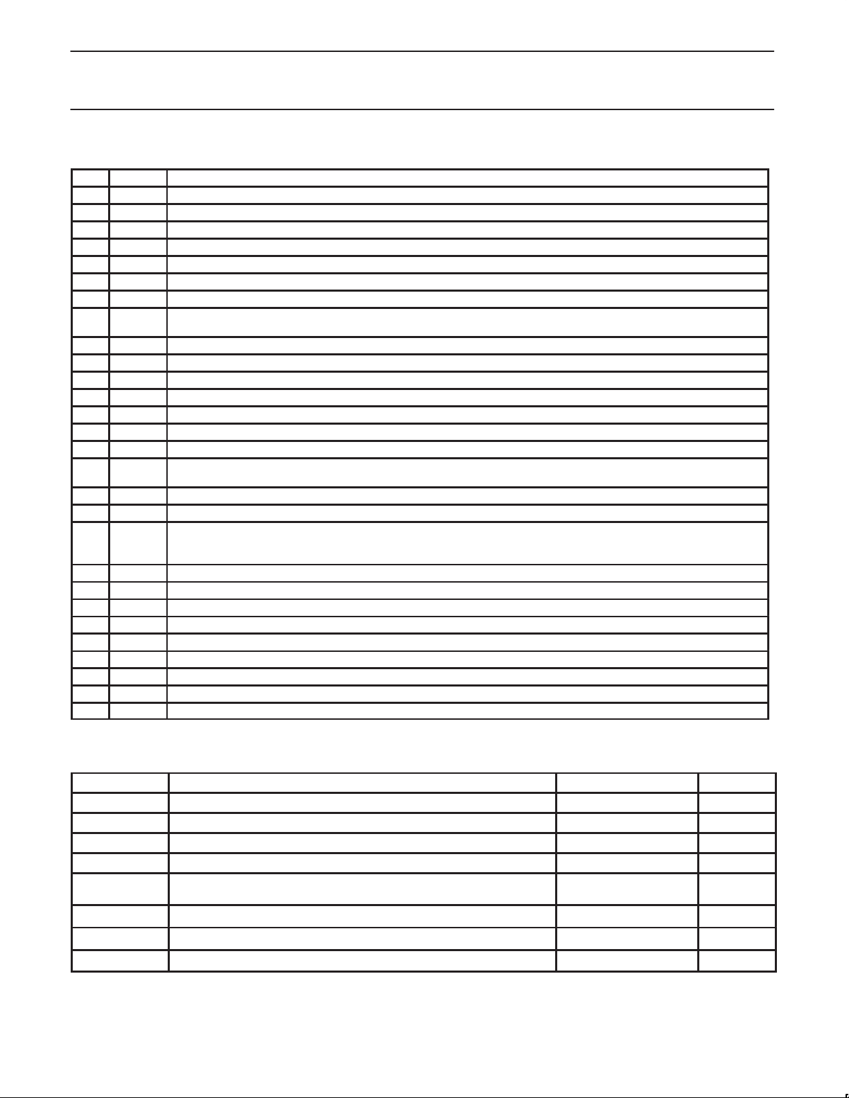
Table 2. SA5775A Pin Descriptions for the D Package (Small Outline)
Pin # Name Function
1. SIN– Negative output connection to the SIN coil of the gauge.
2. SIN+ Positive output connection to the SIN coil of the gauge.
3. NC No connect
4. NC No connect
5. NC No connect
6. A
GND
7. V
8. DATA
9. DAT AINSerial data input. A new data word is serially shifted into the part on the rising edge of S
10. NC No connect
11. NC No connect
12. NC No connect
13. V
14. OE Output drivers are turned off when this input is low. Current draw is minimized.
15. S
16. CS
17. NC No connect
18. NC No connect
19. ST
20. D
21. NC No connect
22. NC No connect
23. A
GND
24. NC No connect
25. NC No connect
26. NC No connect
27. COS– Negative output connection to the COS coil of the gauge.
28. COS+ Positive output connection to the COS coil of the gauge.
Ground for V
Analog supply. Nominally 14.0V.
IGN
Serial data output. Output of the internal shift register. When a new data word is shifted in, the old word is shifted out the
OUT
DATA
OUT
5 V logic supply. The internal latches and registers are set to zero on the rising edge of this signal.
CC
Serial clock input. Data is loaded into the part on the rising edge of S
CLK
supply. Pins 6, 20 and 23 connected on the circuit board.
IGN
pin.
CLK
. The data is shifted in MSB first.
CLK
.
Active high chip select input. When CS is high, the part is enabled to receive a new serial input word. The high-to-low
transition of CS loads the new 10-bit word into the DAC registers and updates the output.
Status output from this IC to indicate that the outputs have been disabled. The outputs may be disabled due to shorted outputs, over temperature conditions, power up reset, or output enable control pin. This output is an open drain output. Multiple
status outputs may be wire OR’ed together. This output is low when the outputs are disabled due to a fault condition.
Ground for VCC supply. Connect to Pins 6 and 23.
GND
Ground for VBB supply. Connect to Pins 6 and 20.
ABSOLUTE MAXIMUM RATINGS
SYMBOL PARAMETER RATING UNIT
V
IGN
V
CC
D
to A
V
P
T
T
θ
GND
IN
D
A
J
JA
GND
NOTE:
1. For power dissipation ratings in still air, derate above 25°C at the following rates:
1999 Sep 20
Analog supply -1 to +23 V
Digital supply -1 to +6 V
Ground difference -0.3 to +0.3 V
Digital input voltage, Data In, OE, CS, S
Power dissipation (TA = 25°C)
1
CLK
-1 to +7 V
D and N packages 1500
Ambient operating temperature –40 to +85
Junction temperature 150
DIP and SO packages 90
D and N packages at 12mW/°C
4
mW
°C
°C
°C/W
Page 5
Philips Semiconductors Product specification
SYMBOL
PARAMETER
TEST CONDITIONS
UNIT
SA5775ADifferential air-core meter driver
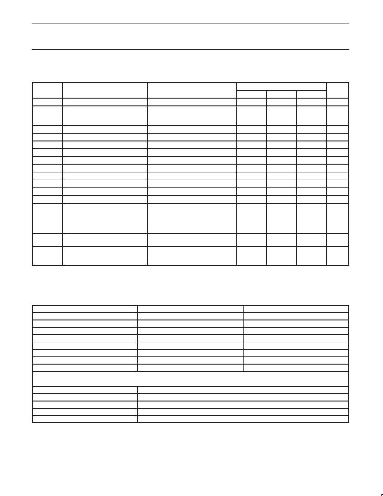
DC ELECTRICAL CHARACTERISTICS
V
= 7.5 to 18 V; VCC = 4.5 to 5.5 V; TA = –40 to +85°C.
IGN
LIMITS
MIN TYP MAX
V
IGN
I
IGN
I
CC
V
OH
V
OL
VOL Status IOL = 2.8 mA 0.8 V
IOH Status ST, VCC = 5 V 25 µA
V
IH
V
IL
I
IH
I
IL
A
CC
I
SD
V
DRIVE
R
LMIN
NOTE:
1. See Test Circuit.
2. Maximum current is when output is 45 degrees; T
3. See Table “Output function accuracy”
Ignition supply voltage 7.5 18 V
Ignition supply current
= 18 V no load
IGN
VBB = 18 V with load
RLC, RLS = R
LMIN
1,2
25
mA
160
V
Logic supply current VCC = 5.5 V 1 mA
Output high voltage Data out IOH = 300 µA VCC – 0.8
Output low voltage Data out IOL = 1.5 mA 0.4 V
Input high voltage CS, S
Input low voltage CS, S
Input high current CS, S
Input low current CS, S
Output function accuracy
3
CLK
CLK
RLC, RLS = R
, DATA
CLK
CLK
, DATA
IN
IN
, DATAIN, VIN = 0.7 x V
, DATAIN, VIN = 0.3 x V
LMIN
CC
CC
0.7 x V
CC
0.3 x V
CC
10 µA
10 µA
–0.5 0.5 Degree
V
V
Output shut-down current COS+, COS–, SIN+, SIN–
Coil drive voltage
Minimum load resistance
I
SINK
I
SOURCEVIGN
= –40°C, and RL = 138 Ω.
A
V
= V
IGN
V
= V
IGN
= V
V
= V
IGN
V
= V
IGN
V
= V
IGN
TA = 85°C
TA = 25°C
TA = –40°C
IGN (MAX)
IGN (MIN)
IGN (MAX)
IGN (MIN)
IGN (MAX)
IGN (MIN)
97
43
85
43
500
300
500
300
68 78 %V
215
171
138
mA
mA
mA
mA
Ω
Ω
Ω
IGN
Table 3. Output function accuracy
Ideal Nominal Input Code
0 0.176 0
45 45.176 128
90 90.176 256
135 135.176 384
180 180.176 512
225 225.176 640
270 270.176 768
360 359.820 1023
Equation for Output Angle (θ) vs Output Voltage
Quadrant Equation
I θ = tan–1 | [(SIN+) – (SIN–)] / [(COS+) – (COS–)] |
II θ = 180° +tan–1 | [(SIN+) – (SIN–)] / [(COS+) – (COS–)] |
III θ = 180° +tan–1 | [(SIN+) – (SIN–)] / [(COS+) – (COS–)] |
IV θ = 360° +tan–1 | [(SIN+) – (SIN–)] / [(COS+) – (COS–)] |
N = Binary Input Code
1999 Sep 20
5
Page 6
Philips Semiconductors Product specification
SYMBOL
PARAMETER
TEST CONDITIONS
UNIT
SA5775ADifferential air-core meter driver
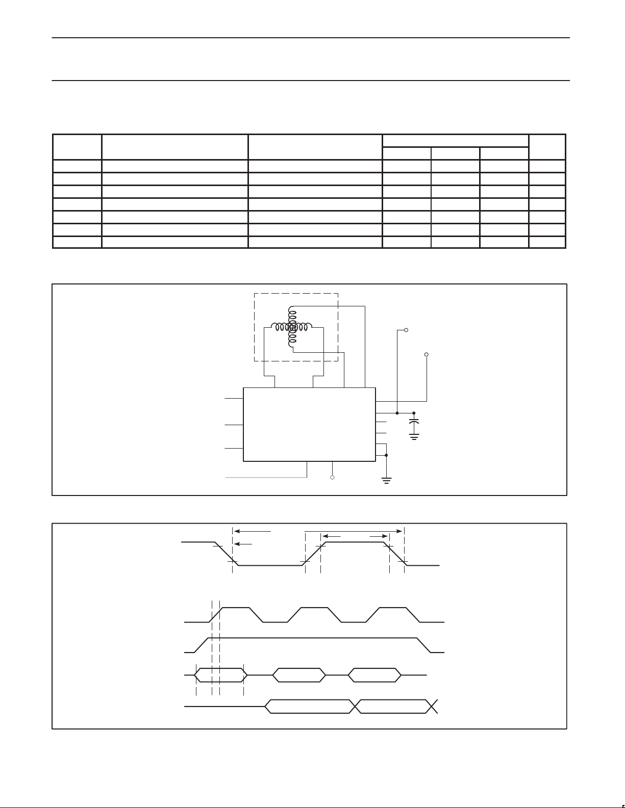
AC ELECTRICAL CHARACTERISTICS
VDD = 7.5 to 18 V; VCC = 4.5 to 5.5 V; TA = –40 to +85°C
LIMITS
MIN TYP MAX
FS
CLK
TS
CLKH
TS
CLKL
TRO Output rise time DO 0.75 to VCC –1.2 V, CL = 90 pF 75 ns
TFO Output fall time DO VCC –1.2 V to 0.75, CL = 90 pF 75 ns
TSU DI set-up time 75 ns
THI DI hold time 75 ns
TYPICAL APPLICATION
Input frequency 1.6 MHz
S
high time 175 ns
CLK
S
low time VCC = 5.5 V 175 ns
CLK
METER
14V
MICROPROCESSOR
SCLK
SCLK
FROM
5
DATA
OUT
9
DATA
IN
6
S
CLK
SA5775A
SGD
OE
Figure 3. Typical application
FSCLKL
TSCLKL
Tr Tf
V
5V
CC
78
COS+COS–SIN+SIN–
V
D
A
TSCLKH
161521
DO
IGN
NC
ST
GND
GND
Data Out
5
4
12
µ
F
10
11
13
14
SL00455
1999 Sep 20
CS
DO
DI
BIT9 BIT8..1 BIT0
T
SUTHI
BIT0
PREVIOUS WORD
SL00456
Figure 4. Serial interface timing
6
Page 7
Philips Semiconductors Product specification
SA5775ADifferential air-core meter driver
1
2
3
4
5
6
7
8
16
15
14
13
12
11
10
9
SL00457
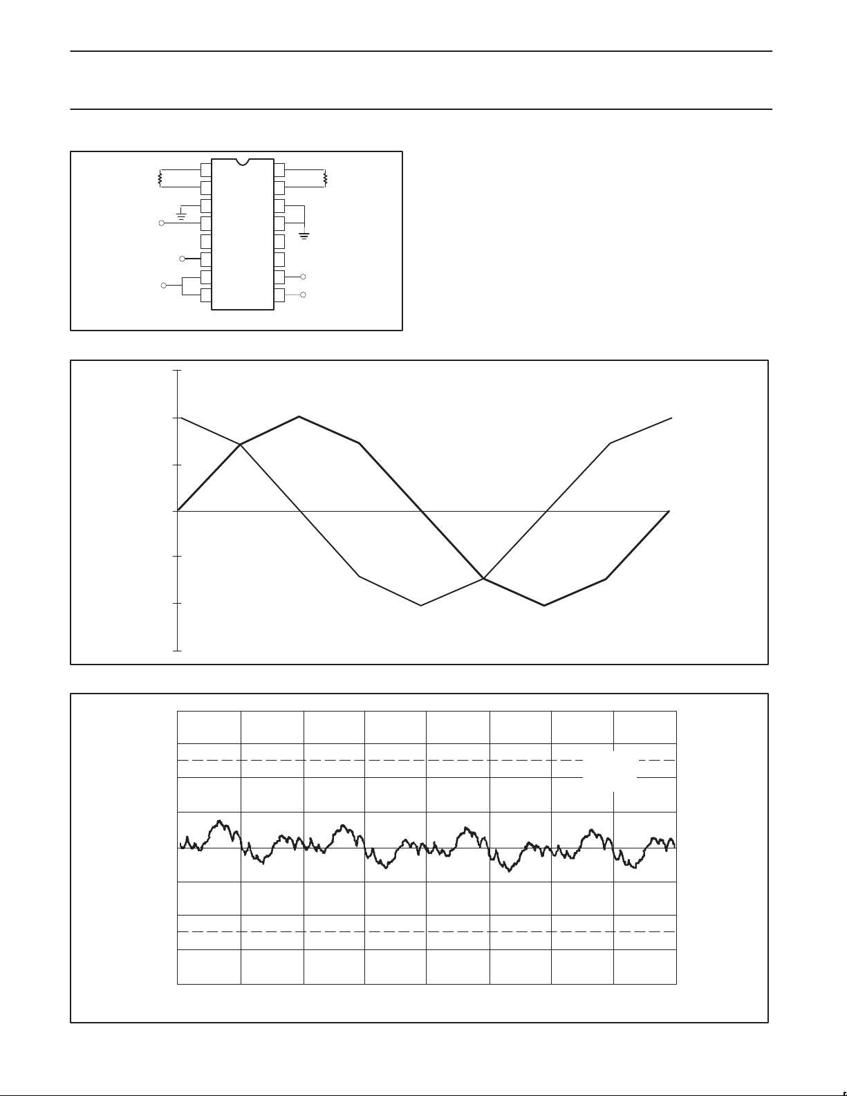
Figure 5. SA5775A Test circuit, N package
15
COS
10
5
0
0 127 255 383 511 639 767 895 1023
DIFFERENTIAL VOLTAGE
–5
SIN
–10
–15
Figure 6. SA5775A output voltages (V
0.8
0.6
0.4
0.2
0.0
ERROR (DEGREES)
–0.2
–0.4
–0.6
–0.8
0 127 255 383 511 639 767 895 1023
INPUT CODE
INPUT CODE
IGN
= 14 V)
VBB = 14V
RL = 200Ω
T = 25
Figure 7. Error graph
SL00458
SL00459
1999 Sep 20
7
Page 8
Philips Semiconductors Product specification
SA5775ADifferential air-core meter driver
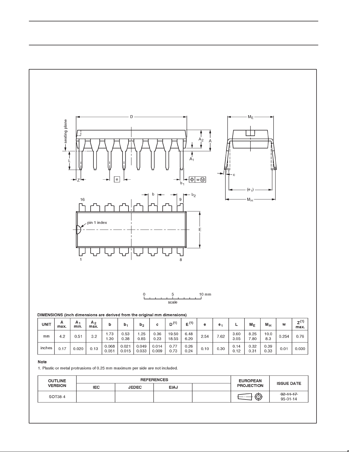
DIP16: plastic dual in-line package; 16 leads (300 mil) SOT38-4
1999 Sep 20
8
Page 9
Philips Semiconductors Product specification
SA5775ADifferential air-core meter driver
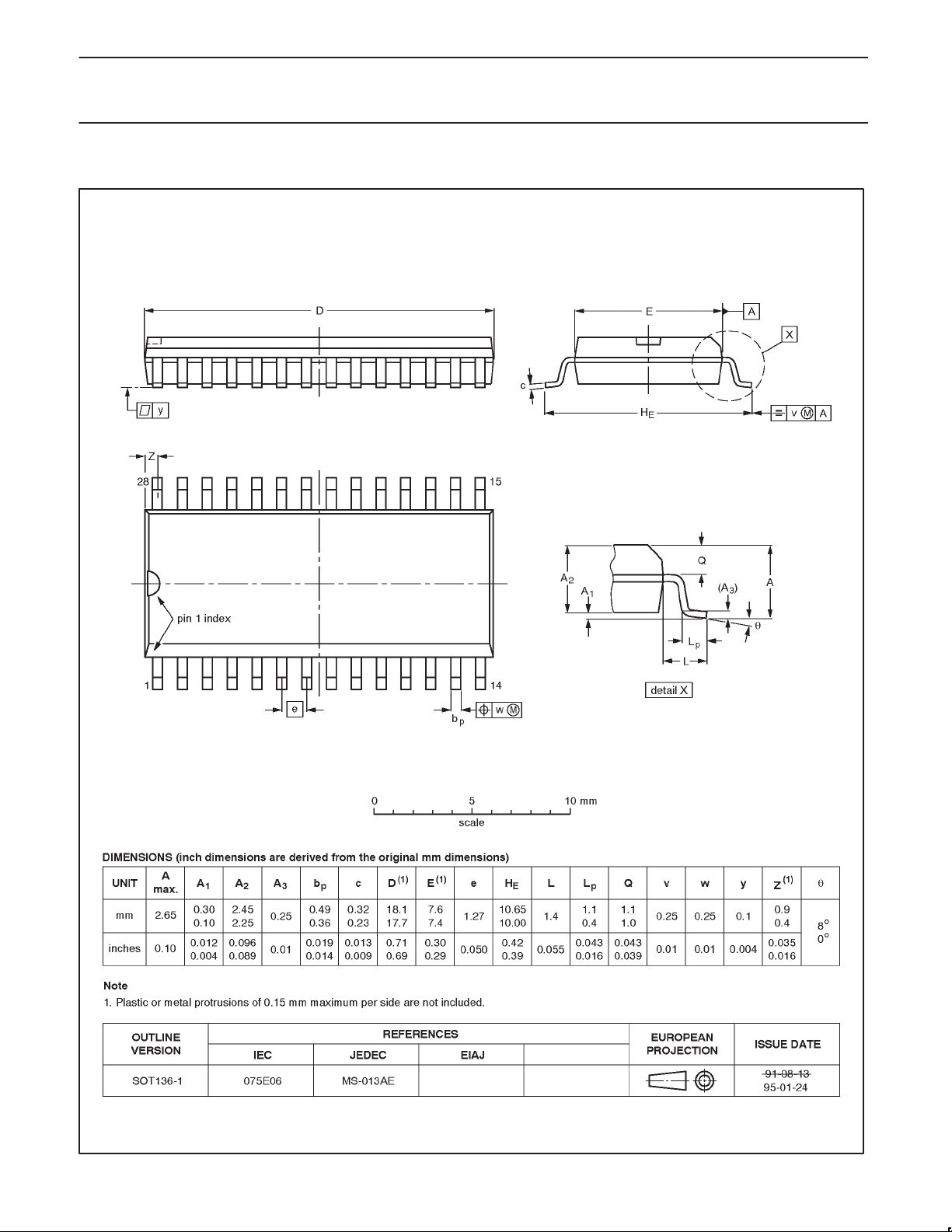
SO28: plastic small outline package; 28 leads; body width 7.5mm SOT136-1
1999 Sep 20
9
Page 10
Philips Semiconductors Product specification
SA5775ADifferential air-core meter driver
Data sheet status
Data sheet
status
Objective
specification
Preliminary
specification
Product
specification
Product
status
Development
Qualification
Production
Definition
This data sheet contains the design target or goal specifications for product development.
Specification may change in any manner without notice.
This data sheet contains preliminary data, and supplementary data will be published at a later date.
Philips Semiconductors reserves the right to make changes at any time without notice in order to
improve design and supply the best possible product.
This data sheet contains final specifications. Philips Semiconductors reserves the right to make
changes at any time without notice in order to improve design and supply the best possible product.
[1]
[1] Please consult the most recently issued datasheet before initiating or completing a design.
Definitions
Short-form specification — The data in a short-form specification is extracted from a full data sheet with the same type number and title. For
detailed information see the relevant data sheet or data handbook.
Limiting values definition — Limiting values given are in accordance with the Absolute Maximum Rating System (IEC 134). Stress above one
or more of the limiting values may cause permanent damage to the device. These are stress ratings only and operation of the device at these or
at any other conditions above those given in the Characteristics sections of the specification is not implied. Exposure to limiting values for extended
periods may affect device reliability.
Application information — Applications that are described herein for any of these products are for illustrative purposes only. Philips
Semiconductors make no representation or warranty that such applications will be suitable for the specified use without further testing or
modification.
Disclaimers
Life support — These products are not designed for use in life support appliances, devices or systems where malfunction of these products can
reasonably be expected to result in personal injury . Philips Semiconductors customers using or selling these products for use in such applications
do so at their own risk and agree to fully indemnify Philips Semiconductors for any damages resulting from such application.
Right to make changes — Philips Semiconductors reserves the right to make changes, without notice, in the products, including circuits, standard
cells, and/or software, described or contained herein in order to improve design and/or performance. Philips Semiconductors assumes no
responsibility or liability for the use of any of these products, conveys no license or title under any patent, copyright, or mask work right to these
products, and makes no representations or warranties that these products are free from patent, copyright, or mask work right infringement, unless
otherwise specified.
Philips Semiconductors
811 East Arques Avenue
P.O. Box 3409
Sunnyvale, California 94088–3409
Telephone 800-234-7381
Copyright Philips Electronics North America Corporation 1999
All rights reserved. Printed in U.S.A.
Date of release: 09-99
Document order number: 9397 750 06445
1999 Sep 20
10
 Loading...