

Page 1
Watkins-Johnson: The Cell Extenders
Power Amplifiers
SA1068A
CDMA 6.3-Watt
1.93 GHz to 1.99 GHz
Linear Power Amplifier Module
The Wireless Edge
™
7. 1303. 750. 870
IN
OUT
3X . 045
8. 00
. 44
J2 CONNECTOR (PANDUIT P/N MLAS156-4)
J1 CONNECTOR (3M P/N 3591-5002)
HEAT SINK MOUNTING SURFACES
. 53
. 53
. 82
3.12
3. 80
7. 490. 510 2.200
.38
3.35
4.24
.37
2.476
6.5805.8303.5303.0301.450
.748
1.036
2.188
1.324
.09
J2 J1
.05
5.400
2X . 38
3X 3. 755
2X SMA JACK
6X Ø .136
SLOT THRU
. 218
. 71
5X .112–40 UNC–2B
.250 MIN THD
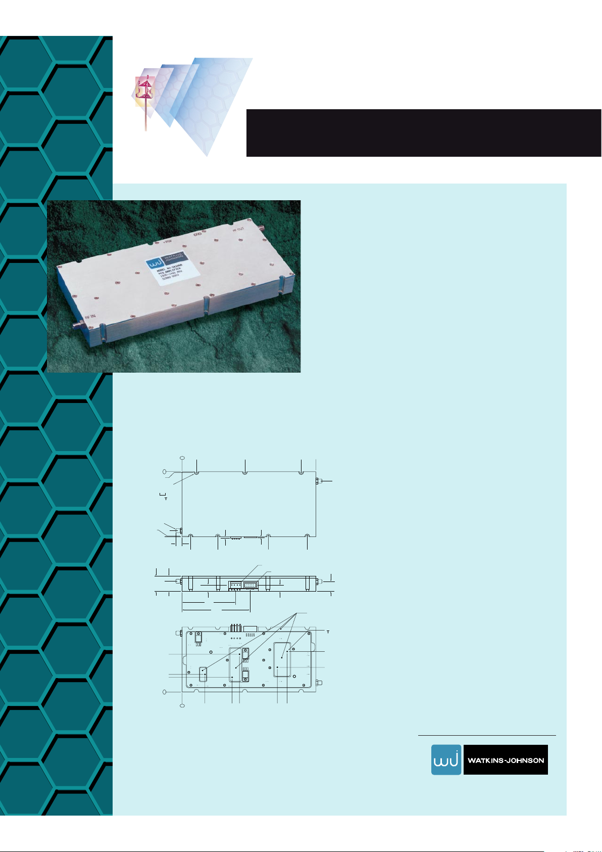
OUTLINE DRAWING
WJ Wireless Products: 1-800-WJ1-4401 • FAX: 650-813-2447 • e-mail: wireless.info@wj.com.
W
atkins-Johnson’s SA1068A Power
Amplifier provides exceptional
linearity for CDMA digital modulation
applications. Utilizing WJ’s GaAs ampli-
fiers driving bipolar transistors in the
class AB output stage, the SA1068A
achieves a high third-order intercept
point combined with superior efficiency
when compared to an equivalent power
class A amplifier. Special non-linear
design techniques are utilized to mini-
mize unwanted adjacent channel power.
To aid top level system diagnostics and
reliability, the unit includes alarms to
identify if an active part fails or if a poor
load is presented to the RF output. In
the event that a fault is detected or to
simply save DC power, a digitally con-
trolled shutdown is provided. An integral
logarithmic power detector measures
the output power of the amplifier over
a 16 dB dynamic range.
■
6.3 Watts CDMA IS-95
■
+45 dBm P1dB
■
45 dB Gain
■
-30°C to +85°C
Page 2

Watkins-Johnson: The Cell Extenders
Power Amplifiers
The Wireless Edge
™
SA1068A
CDMA 6.3-Watt 1.93 GHz to 1.99 GHz
Linear Power Amplifier Module
Note: 1. CDMA adjacent channel power and spurious measurements are made using a Rohde & Schwarz
SMIQ 03 source in an IS-95 forward link.
WATKINS-JOHNSON COMPANY • 3333 Hillview Avenue • Palo Alto, CA 94304-1223
Specifications
Parameters Typical Level Specified Limits
Frequency 1.930-1.990 GHz
Pout at 1 dB Gain Compression +45 dBm
Gain (small signal at +25°C) 45 ±1.0 dB
Gain Variation over Temp (-40 to +85°C). Variation is relative to G(+25°C) ±1.5 dB
CDMA Adjacent Channel Power Rejection (ACPR)1First channel ACP Rejection
(885 KHz offset from f
°
, in a 30 KHz integration BW) Pout ≤ -38 dBm -47 dB -45 dB
Spurious Suppression Outside Frequency Block
a) ACP level at 1.25 to 2.25 MHz offset from f°, in a 12.5 KHz integration BW.
Pout ≤ 38.0 dBm -14 dBm -13 dBm
b) ACP level at 2.25 to 3.25 MHz offset from f°, in a 1.0 MHz integration BW.
Pout ≤ 38.0 dBm -14 dBm -13 dBm
Third-Order 2-Tone Output Intermodulation Product
Rejection (Pout = +37 dBm per CW tone) -35 dB -30 dB
Maximum Noise Figure 5.0 dB 6.5 dB
Input & Output Impedence 50 Ohm
Return Loss (1.930-1,990 GHz)
Input and Output -20 dB -15 dB
Load Mismatch Sustainable Without Damage 3.0:1
Output Power Monitor
a) Pout = +40 dBm CW 4.5 V 5.0 V max, 4.0 V min
b) Pout = +32 dBm CW 2.5 V 3.0 V max, 2.0 V min
c) Pout = +24 dBm CW 0.5 V 1.0 V max, 0.0 V min
Supply Voltages +24 V 23.5 - 26.5 V
Maximum Supply Without Damage, +24 volt supply +28 VDC
Maximum DC Current (+38 dBm Pout), +24 volt supply 4.1 A 4.5 A
Maximum DC Power Dissipation, +24 volt supply 100 Watts 110 Watts
RF Connectors SMA Female
Stability (No spurious outputs above -50 dBm) Unconditionally stable for all loads
Size (Heat sink not included) 0.82" (H), 3.80" (W), 8.00" (L)
Weight (Heat sink not included) 625 grams (22 oz.)
 Loading...