

Page 1

64 CH SEGMENT DRIVER FOR DOT MATRIX LCD
S6B0108
written permission of LCD Driver IC Team.
June. 2000.
Ver. 0.0
Contents in this document are subject to change without notice. No part of this document may be reproduced
or transmitted in any form or by any means, electronic or mechanical, for any purpose, without the express
Page 2
S6B0108 64CH SEGMENT DRIVER FOR DOT MATRIX LCD
INTRODUCTION
The S6B0108 is a LCD driver LSI with 64 channel output for dot matrix liquid crystal graphic display systems.
This device consists of the display RAM, 64 bit data latch, 64 bit drivers and decoder logic. It has the internal display RAM for storing the display data transferred from a 8 bit micro controller and generates the dot matrix Iiquid
crystal driving signals corresponding to stored data. The S6B0108 composed of the liquid crystal display system
in combination with the S6B0107 (64 channel common driver).
FEATURES
• Dot matrix LCD segment driver with 64 channel output
• Input and output signal
- Input: 8 bit parallel display data control signal from MPU divided bias voltage
(V0R, V0L, V2R, V2L, V3R, V3L, V5R, V5L)
- Output: 64 channel for LCD driving.
• Display data is stored in display data RAM from MPU.
• Interface RAM
- Capacity: 512 bytes (4096 bits)
- RAM bit data: RAM bit data = 1: On
RAM bit data = 0: Off
• Applicable LCD duty: 1/32-1/64
• LCD driving voltage: 8V-17V (VDD-VEE)
• Power supply voltage: + 5V ± 10%
• Interface
Drivers
Common Segment
S6B0107 Other S6B0108 MPU
• High voltage CMOS process.
• Bare chip available
Controller
2
Page 3

64CH SEGMENT DRIVER FOR DOT MATRIX LCD S6B0108
S64
S63
S2
S1
BLOCK DIAGRAM
CL
Display
On/Off
Register
1
6
Input
DB<0:7>
8
Output
Register
Busy
Y-Counter
6
Y-Counter
64
8
6
Instruction
Decoder
3
X-Decoder
CLK1
8
CLK2
I/O Buffer
CS1B
CS2B
CS3
R/W
RS
E
RSTB
ADC
FRM
V0L
V2L
V3L
V5L
6
64
Z-Decoder
Display Data RAM
512 × 8 = 4096bits
8
Page Selector
Display Start Line Register
64
Data Latch
64
V0R
LCD Driver
M
V2R
V3R
V5R
3
Page 4
S6B0108 64CH SEGMENT DRIVER FOR DOT MATRIX LCD
S43
S42
S41
S40
S39
S38
S37
S36
S35
S34
S33
S32
S31
S30
S29
S28
S27
S26
S25
S24
S23
S22
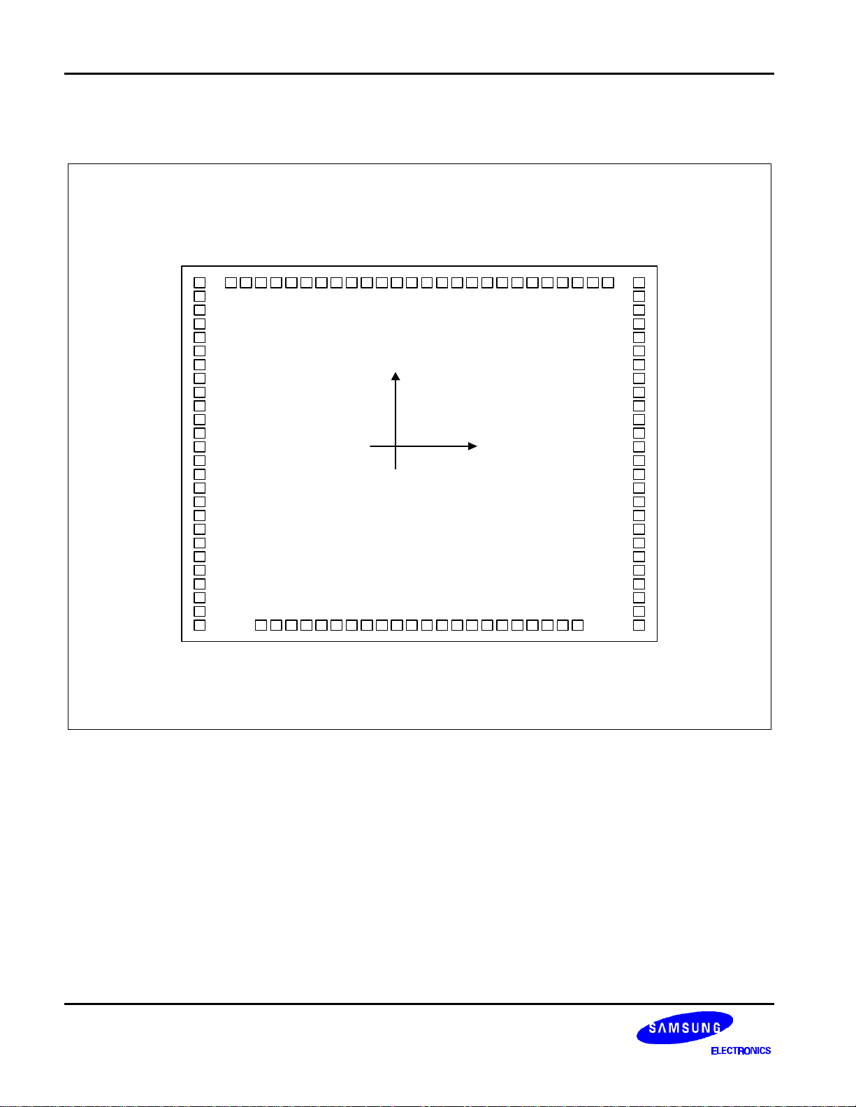
PAD DIAGRAM
V3R
V2R
V5R
V0R
V
S64
S63
S62
S61
S60
S59
S58
S57
S56
S55
S54
S53
S52
S51
S50
S49
S48
S47
S46
S45
S44
EE2
10
11
12
13
14
15
16
17
18
19
20
21
22
23
24
25
26
27
28
29
VDDMADC
321
4
5
6
7
8
9
FRMECLK1
10099989796959493929190898887868584838281807978
CLK2CLRS
Chip size: 4090
PAD size: 100
Unit : µm
R/W
Y
RSTB
CS1B
CS2B
CS3NCNCNCDB7
(0, 0) X
×
×
4020
100
DB6
DB5
DB4
DB3
DB2
DB1
DB0
VSS
77
76
75
74
73
72
71
70
69
68
67
66
65
64
63
62
61
60
59
58
57
56
55
54
53
52
V3L
V2L
V5L
V0L
V
EE1
S1
S2
S3
S4
S5
S6
S7
S8
S9
S10
S11
S12
S13
S14
S15
S16
S17
S18
S19
S20
S21
303132333435363738394041424344454647484950
There is mark of S6B0108 on the bottom left in the chip.
4
51
Page 5

64CH SEGMENT DRIVER FOR DOT MATRIX LCD S6B0108
PAD CENTER COORDINATES
PAD
Number
1 ADC -1140 1845 35 S38 -687 -1845 69 S4 1882 791
2 M -1275 1845 36 S37 -562 -1845 70 S3 1882 916
3 VDD -1410 1845 37 S36 -437 -1845 71 S2 1882 1041
4 V3R -1882 1809 38 S35 -312 -1845 72 S1 1882 1166
5 V2R -1882 1684 39 S34 -187 -1845 73 VEE1 1882 1310
6 V5R -1882 1559 40 S33 -62 -1845 74 V0L 1882 1435
7 V0R -1882 1434 41 S32 62 -1845 75 V5L 1882 1559
8 VEE2 -1882 1309 42 S31 187 -1845 76 V2L 1882 1684
9 S64 -1882 1165 43 S30 312 -1845 77 V3L 1882 1809
10 S63 -1882 1040 44 S29 437 -1845 78 VSS 1412 1845
11 S62 -1882 915 45 S28 562 -1845 79 DB0 1277 1845
12 S61 -1882 790 46 S27 687 -1845 80 DB1 1142 1845
13 S60 -1882 665 47 S26 812 -1845 81 DB2 1007 1845
14 S59 -1882 540 48 S25 937 -1845 82 DB3 882 1845
15 S58 -1882 415 49 S24 1062 -1845 83 DB4 757 1845
16 S57 -1882 290 50 S23 1187 -1845 84 DB5 632 1845
17 S56 -1882 165 51 S22 1487 -1845 85 DB6 507 1845
18 S55 -1882 40 52 S21 1882 -1379 86 DB7 382 1845
19 S54 -1882 -84 53 S20 1882 -1239 87 NC
20 S53 -1882 -209 54 S19 1882 -1099 88 NC
21 S52 -1882 -334 55 S18 1882 -959 89 NC
22 S51 -1882 -459 56 S17 1882 -834 90 CS3 245 1845
23 S50 -1882 -584 57 S16 1882 -709 91 SC2B 120 1845
24 S49 -1882 -709 58 S15 1882 -584 92 SC1B -5 1845
25 S48 -1882 -834 59 S14 1882 -459 93 RSTB -130 1845
26 S47 -1882 -959 60 S13 1882 -334 94 R/W -255 1845
27 S46 -1882 -1099 61 S12 1882 -209 95 RS -380
28 S45 -1882 -1239 62 S11 1882 -84 96 CL -505 1845
29 S44 -1882 -1379 63 S10 1882 41 97 P2 -630 1845
30 S43 -1487 -1845 64 S9 1882 166 98 P1 -755 1845
31 S42 -1187 -1845 65 S8 1882 291 99 E -880 1845
32 S41 -1062 -1845 66 S7 1882 416 100 FRM -1005 1845
33 S40 -937 -1845 67 S6 1882 541
34 S39 -812 -1845 68 S5 1882 666
PAD
Name
Coordinate Coordinate Coordinate
X Y
Pad
Number
Pad
Name
X Y
Pad
Number
Pad
Name
X Y
1845
5
Page 6

S6B0108 64CH SEGMENT DRIVER FOR DOT MATRIX LCD
PIN DESCRIPTION
Table 1. Pin Description
Pin Number
QFP(TQFP)
Symbol
Input /
Output
Description
For internal logic circuit (+5V ± 10%)
V
V
V
DD
SS
EE1.2
Power
GND (0V)
For LCD driver circuit
VSS = 0V, VDD = +5V ± 10%, VDD-VEE = 8V - 17V
3(1)
78(76)
73(71), 8(6)
VEE1 and VEE2 is connected by the same voltage.
Bias supply voltage terminals to drive the LCD.
74(72), 7(5)
76(74), 5(3)
77(75), 4(2)
75(73), 6(4)
V0L, V0R
V2L, V2R
V3L, V3R
V5L, V5R
Power
Select Level
V0L(R), V5L(R)
Non-Select Level
V2L(R), V3L(R)
V0L and V0R (V2L & V2R, V3L & V3R, V5L & V5R) should be
connected by the same voltage.
92(89)
91(87)
90(86)
CS1B
CS2B
CS3
Input
Chip selection
In order to interface data for input or output, the terminals
have to be CS1B = L, CS2B = L, and CS3 = H.
2(100) M Input Alternating signal input for LCD driving.
Address control signal to determine the relation between Y
address of display RAM and terminals from which the data is
1(99) ADC Input
output.
ADC = H → Y0: S1 - Y63: S64
ADC = L → Y0: S64 - Y63: S1
Synchronous control signal.
100(98) FRM Input
Presets the 6-bit Z counter and synchronizes the common
signal with the frame signal when the frame signal becomes
high.
Enable signal.
Write mode (R/W = L) → data of DB<0:7> is latched at the
99(97) E Input
falling edge of E.
Read mode (R/W = H) → DB<0:7> appears the reading data
while E is at high level.
98(96)
97(95)
CLK1
CLK2
Input
2 phase clock signal for internal operation.
Used to execute operations for input/output of display RAM
data and others.
Display synchronous signal.
96(94) CL Input
Display data is latched at rising time of the CL signal and
increments the Z-address counter at the CL falling time.
Data or Instruction.
95(93) RS Input
RS = H → DB<0:7>: Display RAM data
RS = L → DB<0:7>: Instruction data
6
Page 7

64CH SEGMENT DRIVER FOR DOT MATRIX LCD S6B0108
Table 1. Pin Description (Continued)
Pin Number
QFP(TQFP)
Symbol
Input /
Output
94(92) R/W Input
79-86
(77-84)
72-9
(70-7)
DB0-DB7 Input/Output
S1-S64 Output
93(91) RSTB Input
Description
Read or Write.
R/W = H → Data appears at DB<0:7> and can be read by the
CPU while E = H, CS1B = L, CS2B = L and
CS3 = H .
R/W = L → Display data DB<0:7> can be written at falling of E
when CS1B = L, CS2B = L and CS3 = H.
Data bus.
Three state I/O common terminal.
LCD segment driver output.
Display RAM data 1: On
Display RAM data 0: Off (relation of display RAM data & M)
M
L
H
Data
L
H
L
H
Output Level
V
2
V
0
V
3
V
5
Reset signal.
When RSTB=L,
- ON / OFF register becomes set by 0. (display off)
– Display start line register becomes set by 0 (Z-address 0
set,
display from line 0)
After releasing reset, this condition can be changed only by
instruction.
87(85), 88(88)
89(90)
NC No connection. (open)
7
Page 8
S6B0108 64CH SEGMENT DRIVER FOR DOT MATRIX LCD
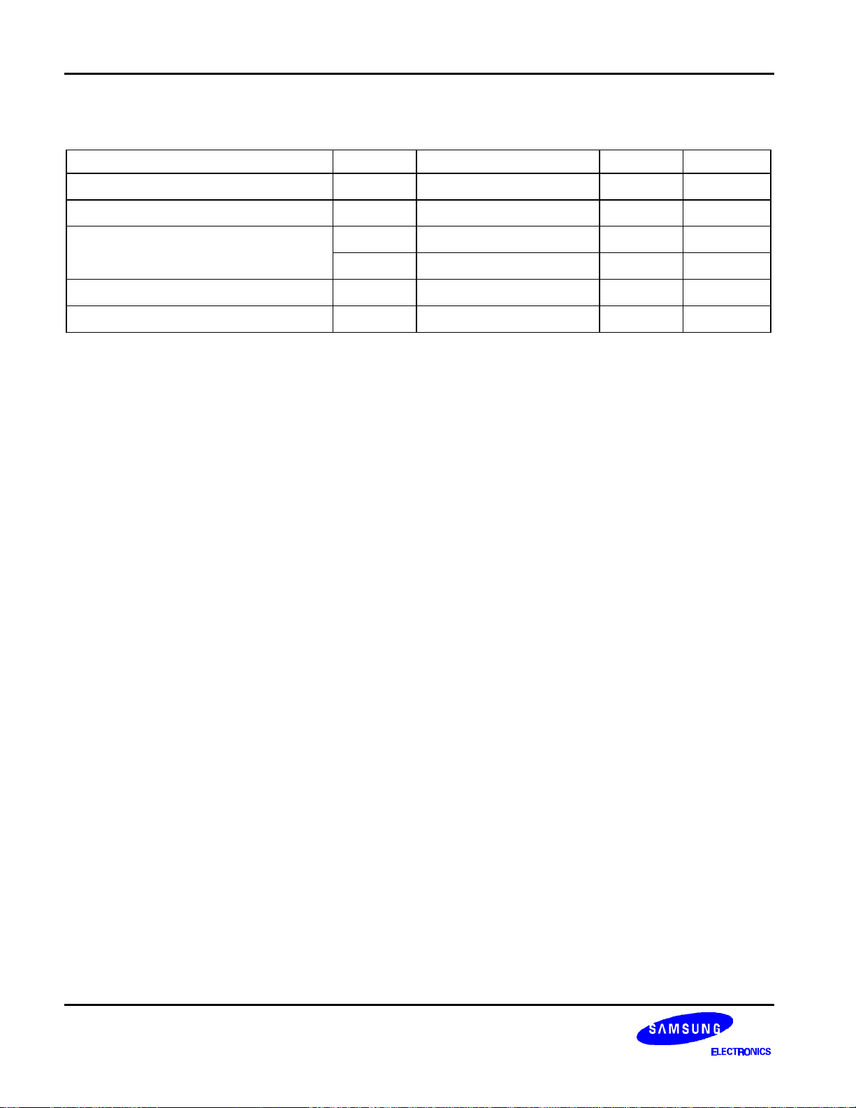
MAXIMUM ABSOLUTE LIMIT
Characteristic Symbol Value Unit Note
and V
V
V
V
V
T
OPR
T
STG
EE2
DD
EE
B
LCD
. V
VDD-19.0 to VDD+0.3
-0.3 to VDD+0.3
VEE-0.3 to VDD+0.3
LCD=VDD-VEE
-0.3 to +7.0 V
V
V
V
-30 to +85 °°C
-55 to +125 °°C
.
Operating voltage
Supply voltage
Driver supply voltage
Operating temperature
Storage temperature
NOTES:
1. Based on V
2. Applies the same supply voltage to V
3. Applies to M, FRM, CL, RSTB, ADC, CLK1, CLK2, CS1B, CS2B, CS3, E, R/W, RS and DB0 - DB7.
4. Applies to V0L(R), V2L(R), V3L(R) and V5L(R).
Voltage level: V
SS
= 0V.
EE1
≥ V0L = V0R ≥ V2L = V2R ≥ V3L = V3R ≥ V5L = V5R ≥ VEE.
DD
(1)
(4)
(1), (3)
(2)
8
Page 9
64CH SEGMENT DRIVER FOR DOT MATRIX LCD S6B0108
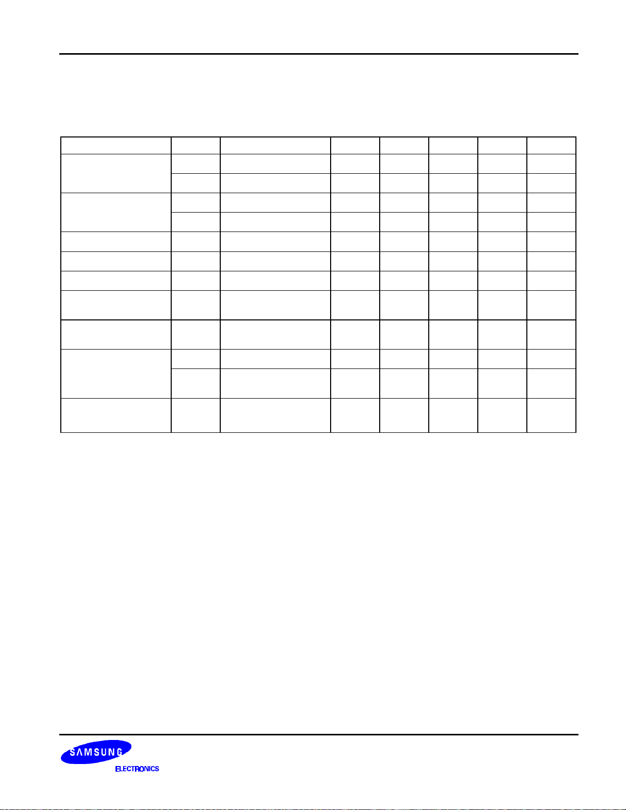
ELECTRICAL CHARACTERISTICS
DC CHARACTERISTICS (V
= +5V ±± 10%, V
DD
= 0V, VDD-V
SS
= 8 to 17V, Ta =-30 to +85°°C)
EE
Characteristic Symbol Condition Min Typ Max Unit Note
Input high voltage
Input low voltage
Output high voltage
Output low voltage
Input leakage current
Three-state(off) input
current
Driver input leakage
current
Operating current
On resistance
V
V
V
V
V
V
I
LKG
I
TSL
I
DIL
I
DD1
I
DD2
R
IH1
IH2
IL1
IL2
OH
OL
ON
I
OH
I
= 1.6mA
OL
V
IN
V
IN
V
IN
During display - - 100
During access
Access cycle = 1MHz
VDD-V
I
LOAD
- 0.7V
DD
- V
- 2.0 - V
- 0 - 0.3V
- 0 - 0.8 V
= -200µA
2.4 - - V
- - 0.4 V
= VSS - V
= VSS - V
= VEE - V
DD
DD
DD
-1.0 - 1.0
-5.0 - 5.0 µA
-2.0 - 2.0 µA
- - 500 µA
= 15V
EE
= ± 0.1mA
- - 7.5 KΩ
DD
DD
DD
V
V
V
µA
µA
(1)
(2)
(1)
(2)
(3)
(3)
(4)
(5)
(6)
(7)
(7)
(8)
NOTES:
1. CL, FRM, M RSTB, CLK1, CLK2
2. CS1B, CS2B, CS3, E, R/W, RS, DB0 - DB7
3. DB0 - DB7
4. Except DB0 - DB7
5. DB0 - DB7 at high impedance
6. V0L(R), V2L(R), V3L(R), V5L(R)
7. 1/64 duty, FCLK = 250kHz, frame frequency = 70HZ, output: no load
8. VDD - VEE = 15.5V
V0L(R) > V2L(R) = VDD - 2/7 (VDD-VEE) > V3L(R) = VEE + 2/7 (VDD-VEE) > V5L(R)
9
Page 10

S6B0108 64CH SEGMENT DRIVER FOR DOT MATRIX LCD
AC CHARACTERISTICS (V
Clock Timing
Characteristic Symbol Min Typ Max Unit
CLK1, CLK2 cycle time
CLK1 "low" level width
CLK2 "low" level width
CLK1 "high" level width
CLK2 "high" level width
CLK1-CLK2 phase difference
CLK2-CLK1 phase difference
CLK1, CLK2 rise time
CLK1, CLK2 fall time
CLK1
CLK2
= +5V ±± 10%, V
DD
t
F
0.7V
DD
0.3V
DD
= 0V, Ta =-30 to +85°°C)
SS
t
CY
t
WL1
t
WL2
t
WH1
t
WH2
t
D12
t
D21
t
R
t
F
t
R
t
t
WL1
D12
0.7V
0.3V
DD
DD
t
F
2.5 - 20
625 - 625 - -
1875 - 1875 - -
625 - 625 - -
- - 150
- - 150
t
CY
t
WH1
t
D21
t
WL2
t
R
t
CY
µs
ns
t
WH2
10
Figure 1. External Clock Waveform
Page 11
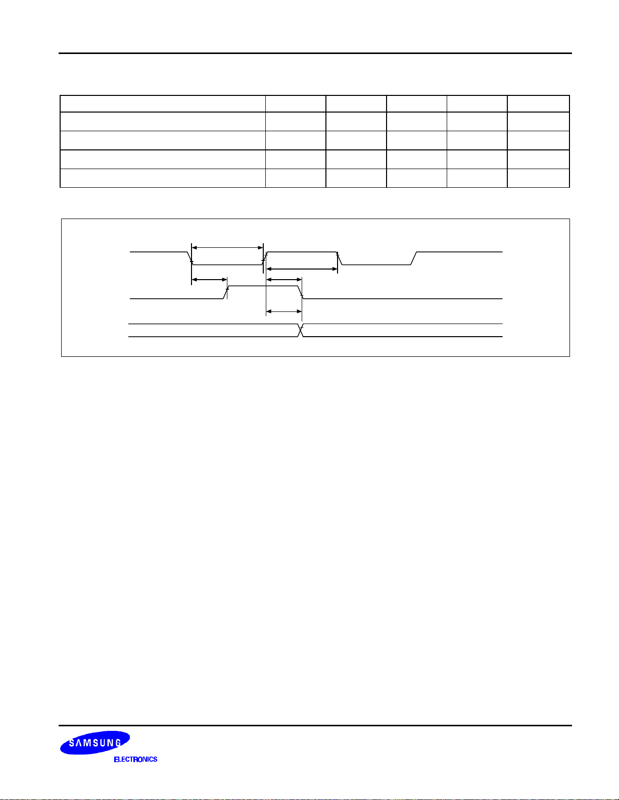
64CH SEGMENT DRIVER FOR DOT MATRIX LCD S6B0108
Display Control Timing
Characteristic Symbol Min Typ Max Unit
FRM delay time
M delay time
CL "low" level width
CL "high" level width
0.7V
0.3V
t
WL
DD
DD
t
DF
0.7V
DD
0.3V
DD
t
DF
t
DM
t
WL
t
WH
t
WH
t
DF
t
DM
0.7V
0.3V
-2 - +2 us
-2 - +2 us
35 - - us
35 - - us
DD
DD
Figure 2. Display Control Waveform
11
Page 12
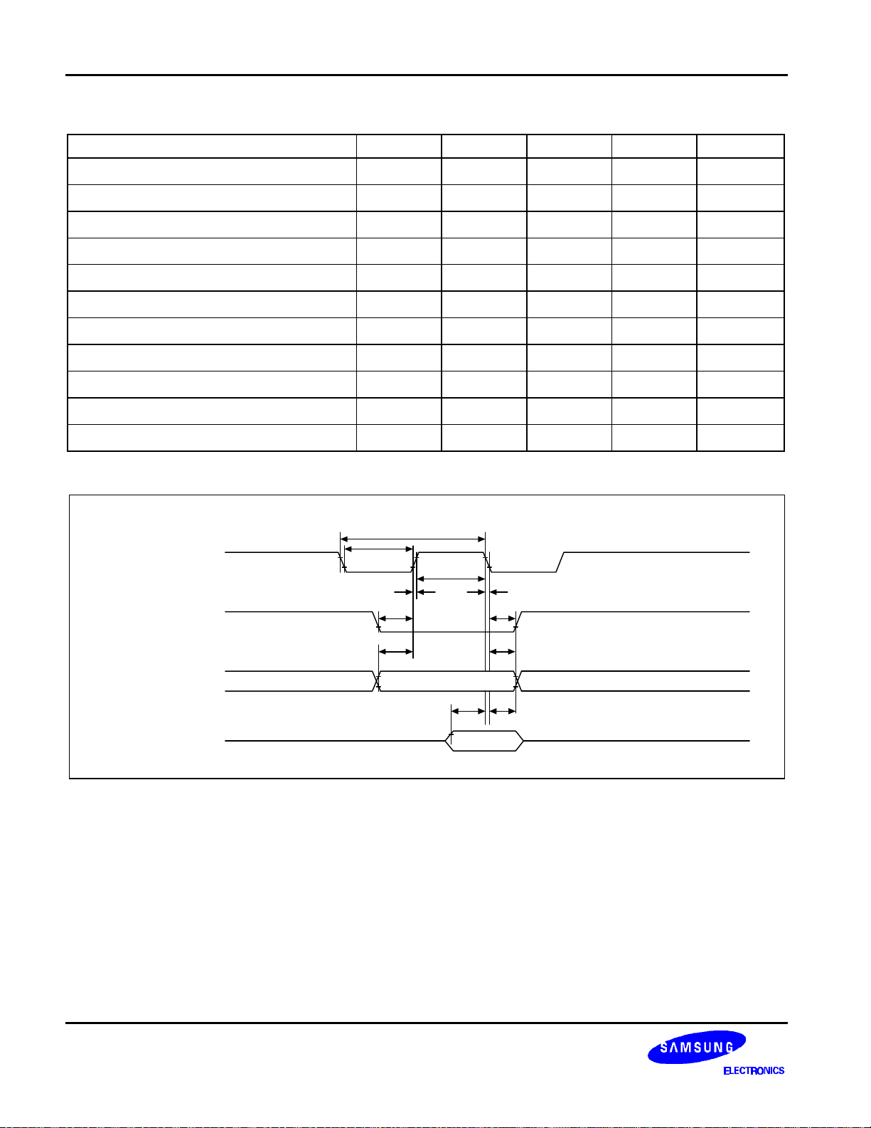
S6B0108 64CH SEGMENT DRIVER FOR DOT MATRIX LCD
MPU Interface
Characteristic Symbol Min Typ Max Unit
E cycle
E high level width
E low level width
E rise time
E fall time
Address set-up time
Address hold time
Data set-up time
Data delay time
Data hold time (write)
Data hold time (read)
t
t
WH
t
WL
t
t
t
ASU
t
AH
t
DSU
t
t
DHW
t
DHR
C
1000 - - ns
450 - - ns
450 - - ns
R
F
- - 25 ns
- - 25 ns
140 - - ns
10 - - ns
200 - - ns
D
- - 320 ns
10 - - ns
20 - - ns
R/W
CS1B, CS2B,
CS3, RS
DB0 - 7
t
C
E
2.0V
0.8V
t
WL
t
R
t
ASU
t
ASU
0.8V 2.0V
t
WH
t
t
F
t
AH
t
AH
DSUtDHW
Figure 3. MPU Write Timing
12
Page 13
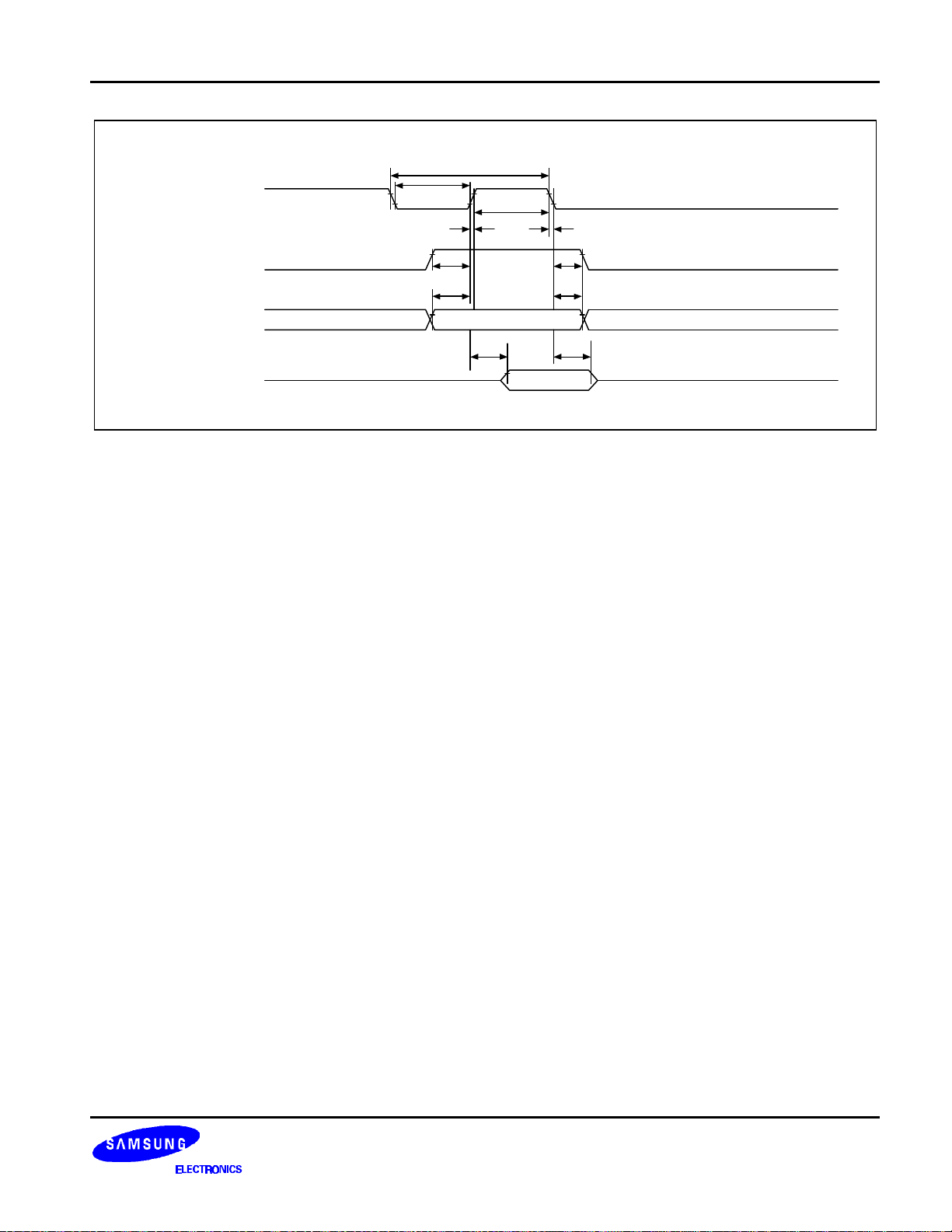
64CH SEGMENT DRIVER FOR DOT MATRIX LCD S6B0108
t
C
t
E
WL
t
R
t
WH
t
F
CS1B, CS2B,
CS3, RS
DB0 - 7
R/W
t
ASU
t
ASU
t
D
t
AH
t
AH
t
DHR
Figure 4. MPU Read Timing
13
Page 14

S6B0108 64CH SEGMENT DRIVER FOR DOT MATRIX LCD
OPERATING PRINCIPLES AND METHODS
I/O BUFFER
Input buffer controls the status between the enable and disable of chip. Unless the CS1B to CS3 is in active
mode, Input or output of data and instruction does not execute. Therefore internal state is not change. But RSTB
and ADC can operate regardless CS1B-CS3.
INPUT REGISTER
Input register is provided to interface with MPU which is different operating frequency. Input register stores the
data temporarily before writing it into display RAM. When CS1B to CS3 are in the active mode, R/W and RS
select the input register. The data from MPU is written into input register. Then Writing it into display RAM. Data
latched for falling of the E signal and write automatically into the display data RAM by internal operation.
OUTPUT REGISTER
Output register stores the data temporarily from display data RAM when CS1B, CS2B and CS3 are in active
mode and R/W and RS = H, stored data in display data RAM is latched in output register. When CS1B to CS3 is
in active mode and R/W = H, RS = L, status data (busy check) can read out. To read the contents of display data
RAM, twice access of read instruction is needed. In first access, data in display data RAM is latched into output
register. In second access, MPU can read data which is latched. That is, to read the data in display data RAM, it
needs dummy read. But status read is not needed dummy read.
RS R/W Function
L
H
L Instruction
H Status read (busy check)
L Data write (from input register to display data RAM)
H Data read (from display data RAM to output register)
14
Page 15
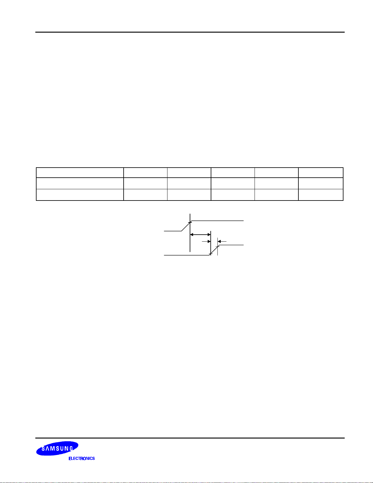
64CH SEGMENT DRIVER FOR DOT MATRIX LCD S6B0108
RESET
The system can be initialized by setting RSTB terminal at low level when turning power on, receiving instruction
from MPU.
When RSTB becomes low, following procedure is occurred.
• Display off
• Display start line register become set by 0. (Z-address 0)
While RSTB is low, No instruction except status read can be accepted. Therefore, execute other instructions after
making sure that DB4 = 0 (clear RSTB) and DB7 = 0 (ready) by status read instruction. The Conditions of power
supply at initial power up are shown in table 1.
Table 2. Power Supply Initial Conditions
Item Symbol Min Typ Max Unit
Reset time
Rise time
t
RS
t
1.0 - - us
R
- - 200 ns
VDD
RSTB
4.5V
t
RS
t
R
0.7V
0.3V
DD
DD
15
Page 16
S6B0108 64CH SEGMENT DRIVER FOR DOT MATRIX LCD
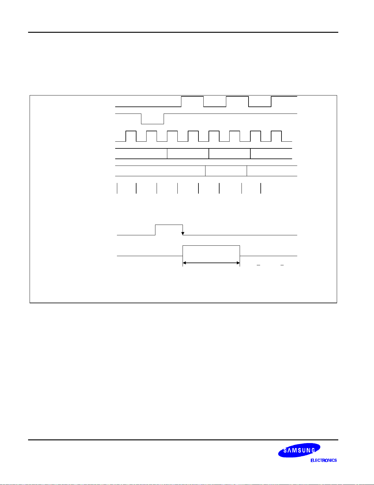
Busy Flag
Busy Flag indicates that S6B0108 is operating or no operating. When busy flag is high, S6B0108 is in internal
operating. When busy flag is low, S6B0108 can accept the data or instruction. DB7 indicates busy flag of the
S6B0108.
RS
R/W
E
Address
Output register
DB0-DB7
Busy Flag
N + 2N + 1N
Data at address N Data at address N+1
Busy
check
Write
address N
Busy
check
Read data
(dummy)
Busy
check
Read data
at address
N
Busy
check
Data read
address N + 1
Busy Check
E
T Busy
1/f
< T Busy < 3/f
f
is CLK1, CLK2 frequency
CLK
CLK
CLK
Busy Flag
16
Page 17

64CH SEGMENT DRIVER FOR DOT MATRIX LCD S6B0108
Display ON / OFF Flip - Flop
The display on/off flip-flop makes on/off the liquid crystal display. When flip-flop is reset (logical low), selective
voltage or non selective voltage appears on segment output terminals. When flip-flop is set (logic high), non
selective voltage appears on segment output terminals regardless of display RAM data. The display on/off flipflop can changes status by instruction. The display data at all segment disappear while RSTB is low. The status
of the flip-flop is output to DB5 by status read instruction. The display on/off flip-flop synchronized by CL signal.
X Page Register
X page register designates pages of the internal display data RAM. Count function is not available. An address is
set by instruction.
Y Address Counter
Y address counter designates address of the internal display data RAM. An address is set by instruction and is
increased by 1 automatically by read or write operations of display data.
Display Data RAM
Display data RAM stores a display data for liquid crystal display. To indicate on state dot matrix of liquid crystal
display, write data 1. The other way, off state, writes 0.
Display data RAM address and segment output can be controlled by ADC signal.
• ADC = H → Y-address 0:S1 - Y address 63:S64
• ADC = L → Y-address 0:S64 - Y address 63:S1
ADC terminal connect the VDD or VSS.
Display Start Line Register
The display start line register indicates of display data RAM to display top line of liquid crystal display. Bit data
(DB<0:5>) of the display start line set instruction is latched in display start line register. Latched data is
transferred to the Z address counter while FRM is high, presetting the Z address counter. It is used for scrolling of
the liquid crystal display screen.
17
Page 18
S6B0108 64CH SEGMENT DRIVER FOR DOT MATRIX LCD
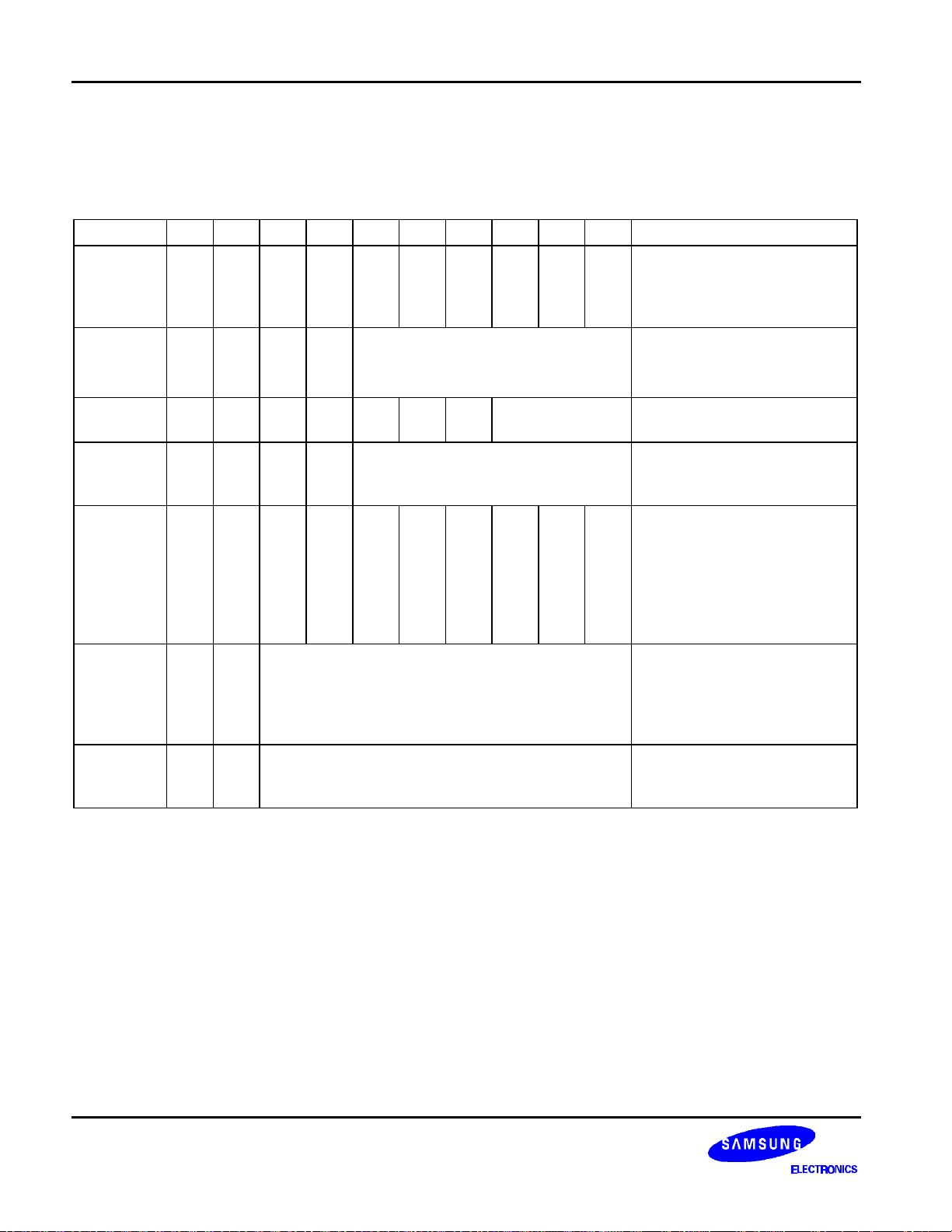
DISPLAY CONTROL INSTRUCTION
The display control instructions control the internal state of the S6B0108. Instruction is received from MPU to
S6B0108 for the display control. The following table shows various instructions.
Instruction RS R/W DB7 DB6 DB5 DB4 DB3 DB2 DB1 DB0 Function
Controls the display on or off.
Display
on/off
Set
address
(Y address)
L L L L H H H H H L/H
L L L H Y address (0 - 63)
Internal status and display
RAM data is not affected.
L: OFF, H: ON
Sets the Y address in the Y
address counter.
Set page
(X address)
L L H L H H H Page (0 - 7)
Display
start line
L L H H Display start line (0 - 63)
(Z address)
Status read L H Busy L
Write
display
H L Write data
data
Read
display
H H Read data
data
On
/
Reset L L L L
Off
Sets the X address at the X
address register.
Indicates the display data
RAM displayed at the top of
the screen.
Read status.
BUSY L: Ready
H: In operation
ON/OFF L: Display ON
H: Display OFF
RESET L: Normal
H: Reset
Writes data (DB0:7) into
display data RAM. After
writing instruction, Y address
is increased by 1
automatically.
Reads data (DB0: 7) from
display data RAM to the data
bus.
18
Page 19
64CH SEGMENT DRIVER FOR DOT MATRIX LCD S6B0108
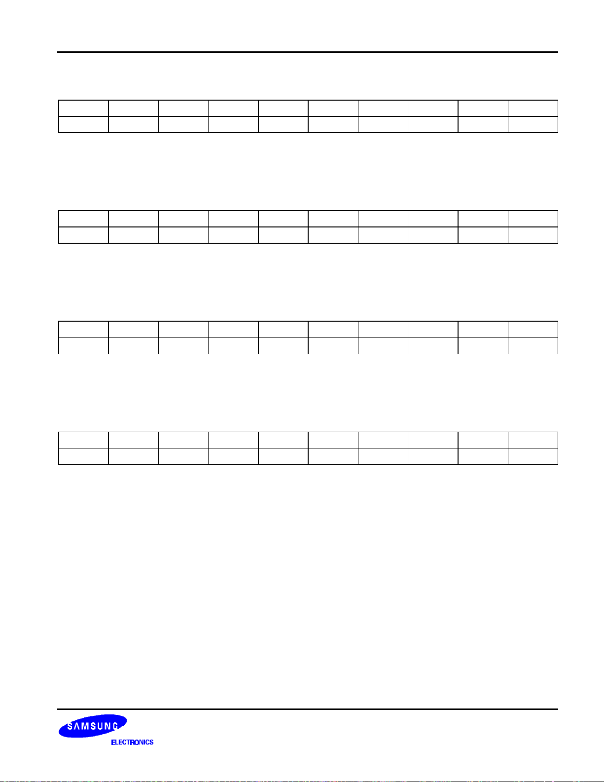
DISPLAY ON / OFF
RS R/W DB7 DB6 DB5 DB4 DB3 DB2 DB1 DB0
0 0 0 0 1 1 1 1 1 D
The display data appears when D is 1 and disappears when D is 0. Though the data is not on the screen with D =
0, it remains in the display data RAM. Therefore, you can make it appear by changing D = 0 into D = 1.
SET ADDRESS (Y ADDRESS)
S R/W DB7 DB6 DB5 DB4 DB3 DB2 DB1 DB0
0 0 0 1 AC5 AC4 AC3 AC2 AC1 AC0
Y address (AC0 - AC5) of the display data RAM is set in the Y address counter. An address is set by instruction
and increased by 1 automatically by read or write operations of display data.
SET PAGE (X ADDRESS)
RS R/W DB7 DB6 DB5 DB4 DB3 DB2 DB1 DB0
0 0 1 0 1 1 1 AC2 AC1 AC0
X address(AC0 - AC2) of the display data RAM is set in the X address register. Writing or reading to or from MPU
is executed in this specified page until the next page is set.
DISPLAY START LINE (Z ADDRESS)
RS R/W DB7 DB6 DB5 DB4 DB3 DB2 DB1 DB0
0 0 1 1 AC5 AC4 AC3 AC2 AC1 AC0
Z address (AC0 - AC5) of the display data RAM is set in the display start line register and displayed at the top of
the screen. When the display duty cycle is 1/64 or others(1/32 - 1/64), the data of total line number of LCD
screen, from the line specified by display start line instruction, is displayed.
19
Page 20
S6B0108 64CH SEGMENT DRIVER FOR DOT MATRIX LCD
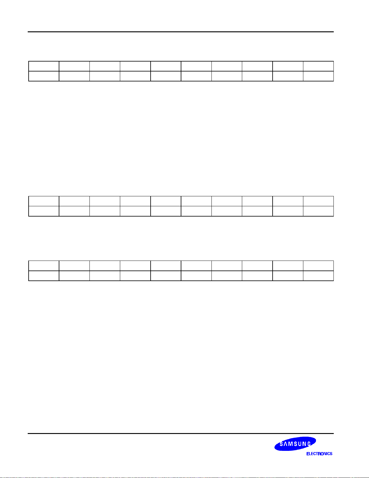
STATUS READ
RS R/W DB7 DB6 DB5 DB4 DB3 DB2 DB1 DB0
0 1 BUSY 0 ON/OFF RESET 0 0 0 0
• BUSY
When BUSY is 1, the Chip is executing internal operation and no instructions are accepted.
When BUSY is 0, the Chip is ready to accept any instructions.
• ON/OFF
When ON/OFF is 1, the display is OFF.
When ON/OFF is 0, the display is ON.
• RESET
When RESET is 1, the system is being initialized.
In this condition, no instructions except status read can be accepted.
When RESET is 0, initializing has finished and the system is in the usual operation condition.
WRITE DISPLAY DATA
RS R/W DB7 DB6 DB5 DB4 DB3 DB2 DB1 DB0
1 0 D7 D6 D5 D4 D3 D2 D1 D0
Writes data (D0 - D7) into the display data RAM. After writing instruction, Y address is increased by 1
automatically.
READ DISPLAY DATA
RS R/W DB7 DB6 DB5 DB4 DB3 DB2 DB1 DB0
1 1 D7 D6 D5 D4 D3 D2 D1 D0
Reads data (D0 - D7) from the display data RAM. After reading instruction, Y address is increased by 1
automatically.
20
Page 21
64CH SEGMENT DRIVER FOR DOT MATRIX LCD S6B0108
R1R
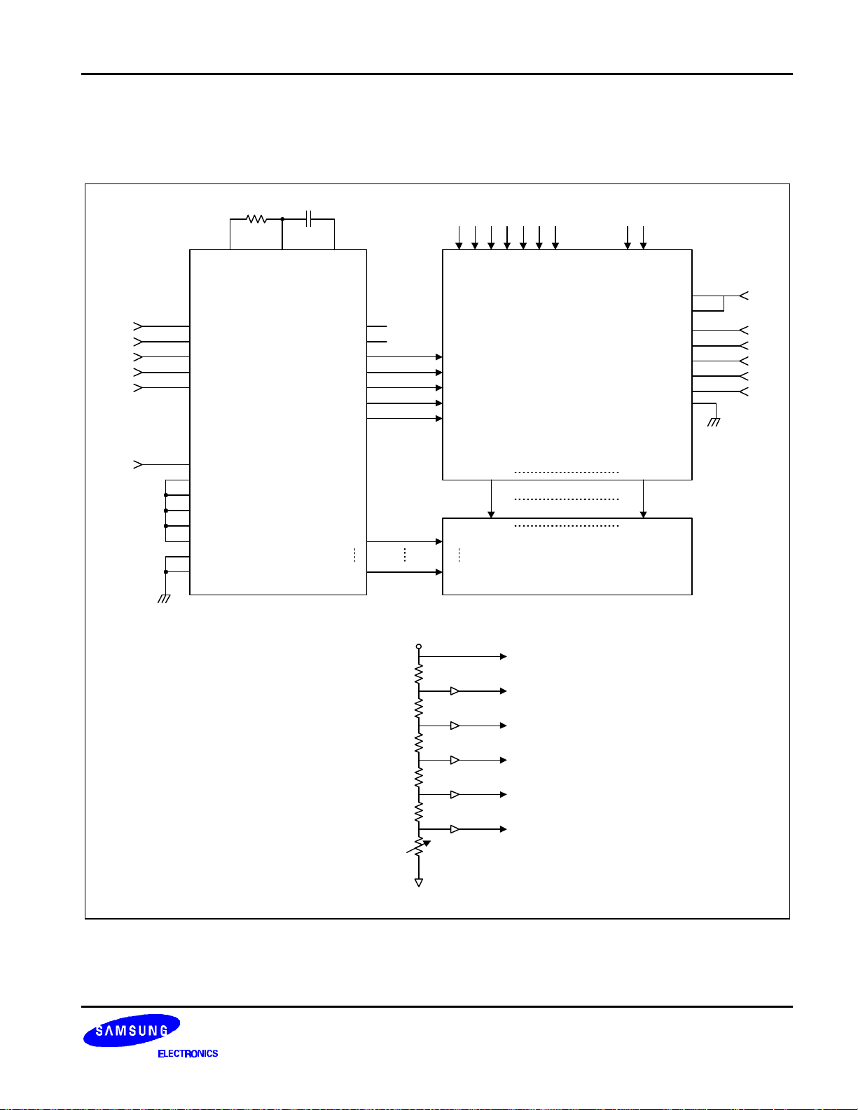
APPLICATION CIRCUIT
1/64 DUTY COMMON DRIVER (S6B0107) INTERFACE CIRCUIT
R/W
RS
From MPU
E
DB0
S6B0108
-
-
DB7
RSTB
V
EE1
ADC
V0R, V
V5R, V
V2R, V
V3R, V
, V
V
V
DD
0L
5L
2L
3L
EE2
SS
V
DD
V
0
V
5
V
2
V
3
V
EE
V
SS
S64
2
R
V
0
V
5
V
1
V
4
V
EE
V0R, V
V5R, V
V1R, V
V4R, V
V
EE
0L
5L
1L
4L
CR
S6B0107
V
DD
V
DD
SHL
C
DIO1
DIO2
FRM
CLK1
CLK2
CL2
CS3
CS2B
CS1B
Open
Open
M
M
FRM
CLK1
CLK2
CL2
S1
FS
MS
PCLK2
SD2
DS1
V
SS
C1
C64
SEG1 SEG64
COM1
LCD
COM64
V
DD
V
R
1
R
1
R
2
R
1
R
1
V
EE
0
V
1
V
2
V
3
V
4
V
5
21
Page 22
S6B0108 64CH SEGMENT DRIVER FOR DOT MATRIX LCD
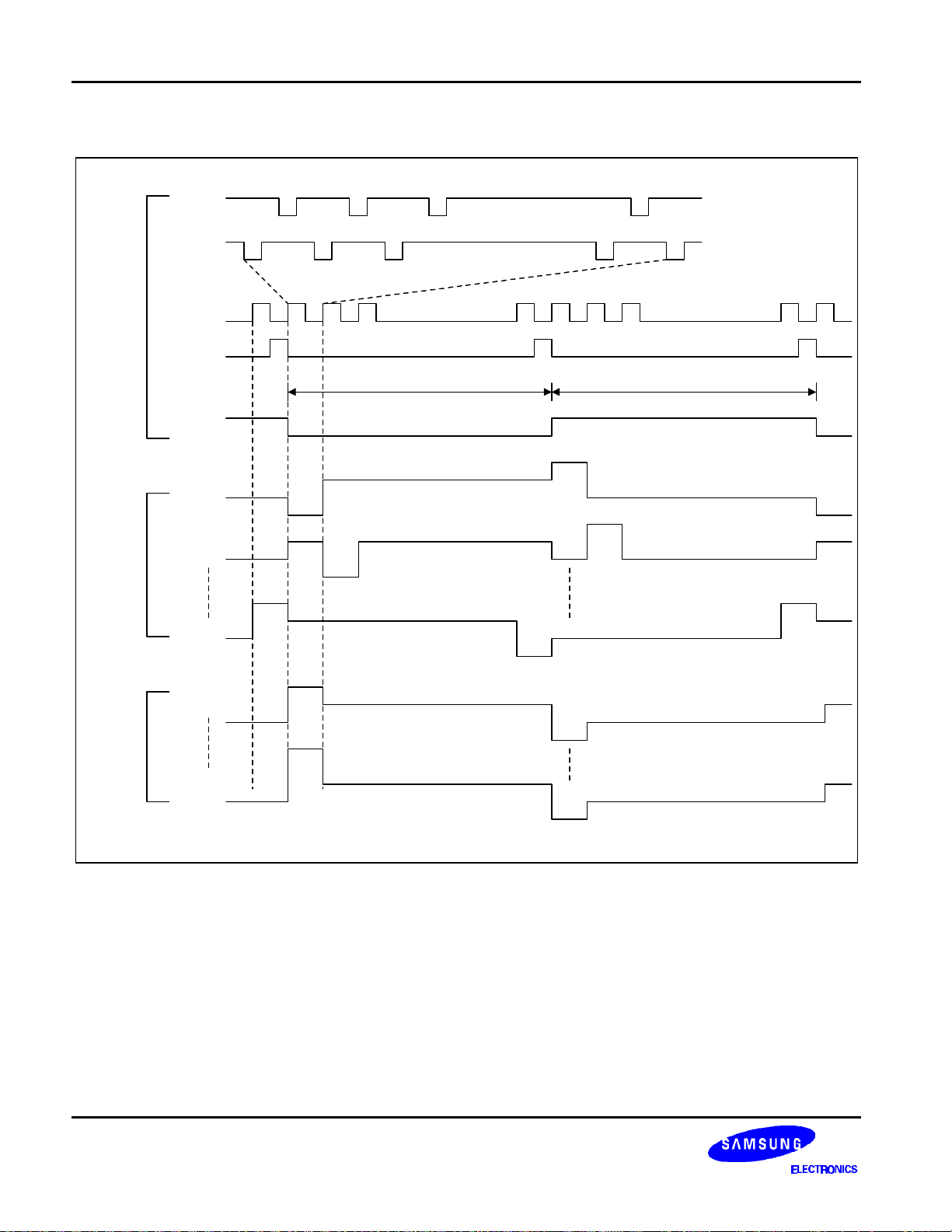
TIMING DIAGRAM (1/64 DUTY)
CLK1
Input
Segment
CLK2
CL
FRM
C1
C2
C64
S1
1 2 3 48 49
64 1 2 3 64 1 2 3 64 1
1 Frame 1 Frame
M
V0
V1
V4
V5
V1
V4
V0
V1
V4
V0
V3
V0
V1
V4
V5
V4
V5
V2
V5
V4
V3
V0
V5
V1
V4
V0
V1
V2
22
S64
V3
V2
V2
V3
V5
Page 23
64CH SEGMENT DRIVER FOR DOT MATRIX LCD S6B0108
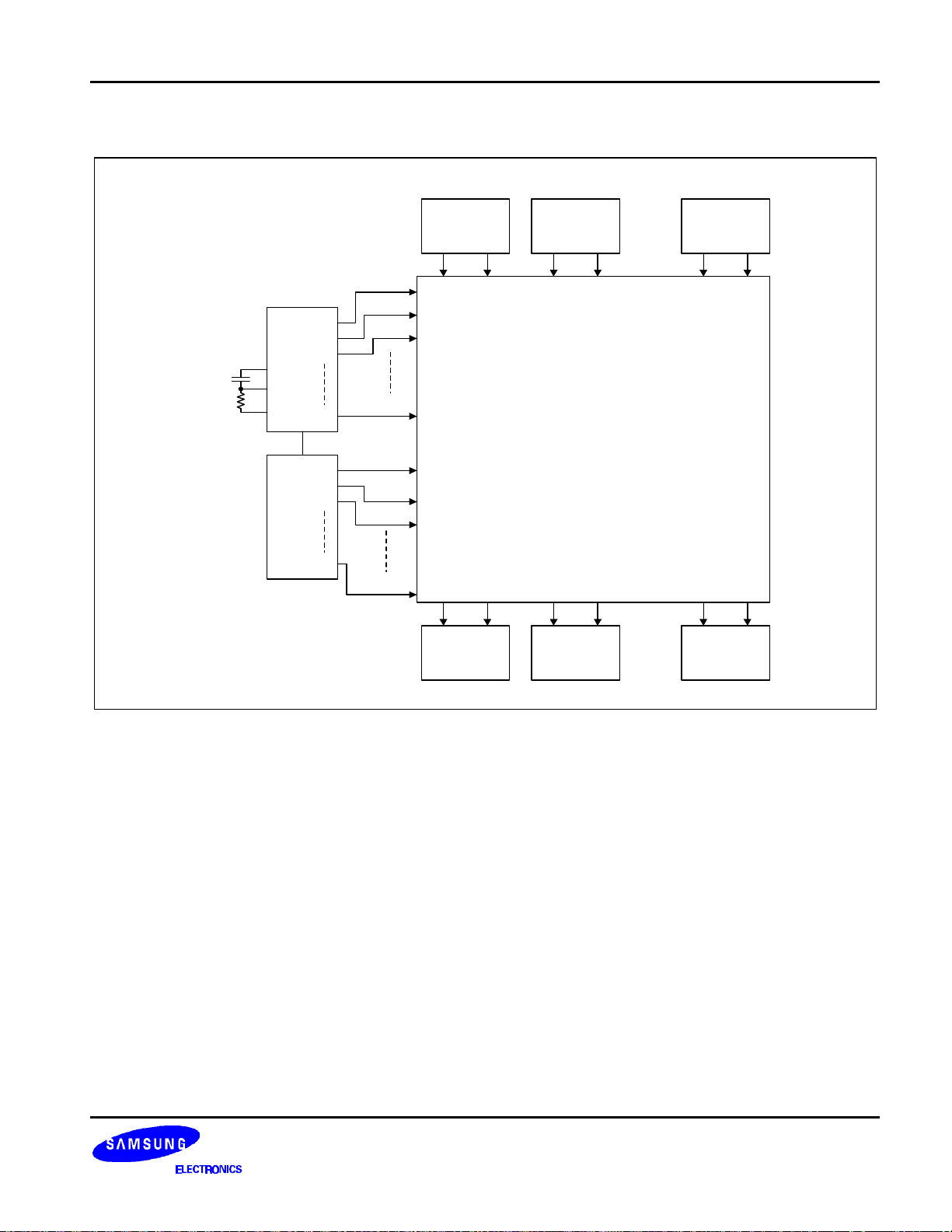
LCD PANEL INTERFACE APPLICATION CIRCUIT
S6B0108
No. 1
S1 ..... S64
S6B0108
No. 2
S1 ..... S64
.....
S6B0108
No. 8
S1 ..... S64
..... ..... .....
S6B0107
(master)
C1
C2
C3
C
f
R
CR
f
R
C64
COM1
COM2
COM3
COM64
LCD Panel
(128 × 512dots)
S1 ..... S64
No. 10
S6B0108
.....
S1 ..... S64
No. 16
S6B0108
C64
S6B0107
(slave)
C1
C2
C3
COM65
COM66
COM67
COM128
..... ..... .....
S1 ..... S64
No. 9
S6B0108
23
 Loading...