

Page 1
INFRAED REMOCON RECEIVER S5G9802X01
INTRODUCTION
TheS5G9802X01 is a CMOS integrated circuit for the infrared ray
remote control transmitter function to be used with the KS9801
for receiver. It can be applied to TV, VCR, VDP, CDP and AV
controller.
The S5G9802X01 has 18 functions, and a total of 75 commands can
be transmitted. These commands are generated by continuous
keys with multiple keying and 12 commands by single shot keys.
FEATURES
• Wide range of operating supply voltage :
VDD = 2.0V - 5V
• Low power consumption : IDS<1 m A at standby mode
• Containing ceramic oscillation circuit
• Function of multiple keying
• Adaptable to various models using custom code bits
ORDERING INFORMATION
16−DIP−300A
Device Package Operating Temperature
S5G9802X01-D0B0 16−DIP−300A − 20°C − + 75°C
1
Page 2
S5G9802X01 INFRAED REMOCON RECEIVER
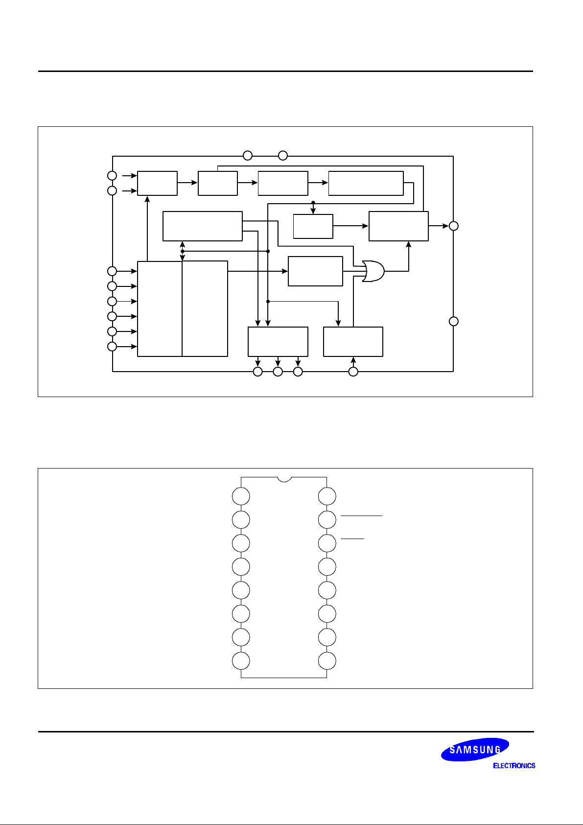
BLOCK DIAGRAM
X
X
K1
K2
K3
K4
K5
K6
V
DD
2
I
3
O
4
5
6
7
8
9
OSC DEVIDER
CONTINUOUS/SINGLE
SHOT CODE
GENERATOR CIRCUIT
KEY
INPUT
CIRCUIT
MULTIKEY
INHIBITING
CIRCUIT
V
SS
116
CLOCK
GENERATOR
TIMING
COUNTER
DATA CODE
GENERATING
CIRCUIT
STROBE SIGNAL
GENERATION
CIRCUIT
10 11 12 13
ST1 ST2 ST3 CC1
ADDRESS COUNTER
& DECODER
CUSTOM CODE
GENERATING
CIRCUIT
OUTPUT
SYNTHESIZING
CIRCUIT
15
14
REM OUT
TEST
Figure 1.
PIN CONFIGURATION
VSS
X
K1
K2
K3
K4
K5
1
2
X
I
3
O
4
5
6
7
8
16
15
14
13
12
11
10
9
VDD
REM OUT
TEST
CC1
ST3
ST2
ST1
K6
Figure 2.
2
Page 3
INFRAED REMOCON RECEIVER S5G9802X01
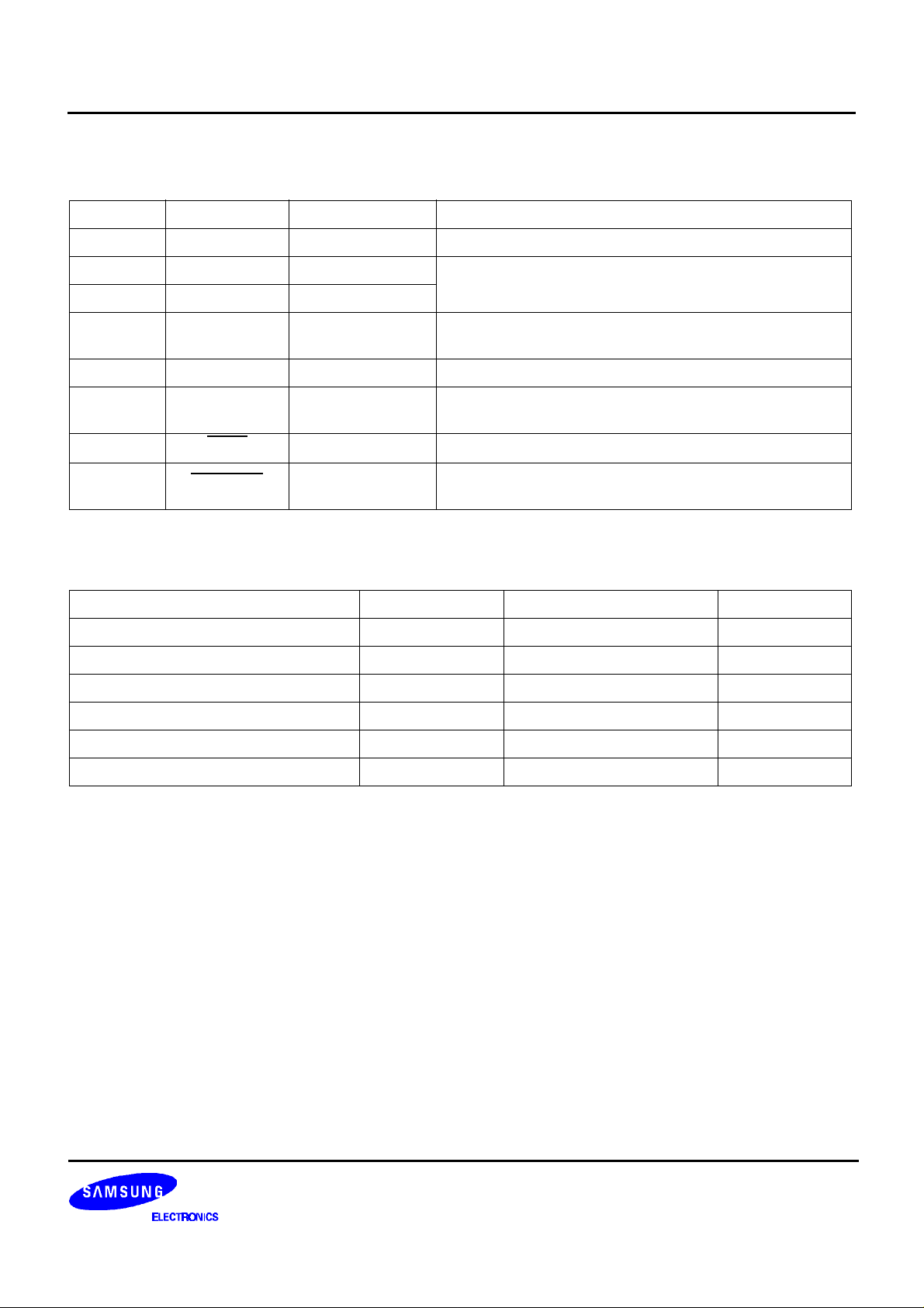
PIN DISCRIPTION
Pin No. Symbol Input/Output Description
1,16 V
2 X
3 X
4~9 K1 ~ K6 Key Input
SS1
, V
I
O
DD
GND, Power Ground, power supply terminals
OSC Input
OSC output
Terminal for OSC, and used for connecting a 455kHz
ceramic resonator
Key input terminal for key matrix (with a built-in pull down
resistor)
10~12 ST1 ~ ST3 Strobe Output Strobe output terminal for key matrix
13 CCI
14
TEST
15 REM-OUT Remote Output
Custom Code
Input
Selected custom code
Test Terminal With a built-in pull up resistor
Remote signal output, modulation is made by 12 bits 1
cycle and 38kHz carrier wave
ABSOLUTE MAXIMUM RATINGS (Ta = 25×C)
Characteristic Symbol Value Unit
Supply Voltage V
Input Voltage V
Power Dissipation P
Operating Temperature T
Storage Temperature T
REM-OUT Output Current I
DD
IN
D
OPR
STG
OUT
VSS −0.3 − VDD+0.3 V
6 V
200 mW
−20 − 75 °C
−55 − +125 °C
−5 mA
3
Page 4

S5G9802X01 INFRAED REMOCON RECEIVER
ELECTRICAL CHARACTERISTICS
(Ta = 25×C , V
= 3V, unless otherwise specified)
DD
Characteristic Symbol Test Conditions Min. Typ. Max. Unit
Operating Voltage V
Operating Current I
Static Current I
K1 − K6
CCI
V
IN
H V
L V
H I
Input
Out
put
K1 ~ K6 I
CCI
TEST L I
ST1 ~
ST3
I
I
OUT
IN
IN
L I
H I
H I
L I
H I
REM-OUT I
OUT
L I
DD
DD
DS
IH
IL
IH
IL
IH
IL
OH
OL
OH
OL
All function operation 2.0 − 50 V
Key on, without LOAD − 0.1 1.0 mA
OSC stop, all key off − − 10 µA
− 0.8 Vdd − Vdd V
− 0 − 0.2 Vdd V
V
= 3.0V 10 20 60 µA
IH
V
= 0V −1.0 − 1.0 µA
IL
V
= 3.0V −1.0 − 1.0 µA
OH
V
= 0V 10 20 60 µA
IL
V
= 2.0V −0.5 − − mA
OH
V
= 3.0V 50 − − µA
OL
V
= 2.0V -0.1 − − mA
OH
V
= 2.0V 1.0 − − mA
OL
OSC Feedback Resistor Rf − − 500 − kΩ
Oscillatiion Frequency f
OSC
− 400 455 500 kHz
4
Page 5

INFRAED REMOCON RECEIVER S5G9802X01
FUNCTIONAL DESCRIPTION
1. OSCILLATION CIRCUIT
• The oscillation circuit is activated when any key is depressed. The ceramic resonator connected to XI, XO is
normally operated at 455kHz oscillation frequency.
fosc
2 3 X
X
I
ceramic
resonator
O
2 3 --- XI, XO Terminals
C1, C2 = 100pF
C2C1
Figure 3.
2. KEY INPUT & STROBE OUTPUT
• All key input pins have a pull down resistor to VSS. 18 keys can be connected by key input K1 - K6 and 6x3
matrix by means of strobe signal ST1 - ST3.
• Multiple keying is possible for the keys connected to ST1 Line (key No. 1 - 6), and all depressed keys are
output (Output becomes continuous pulses).
• Among the strobe signal lines, priority is set in the order, ST1>ST2>ST3.
The keys connected to ST2 and ST3 lines have priority and when input is made through more than 2 keys, and
single signal is preferentially output in order of K1 - K6.
• Finally, the keys connected to ST2 and ST3 lines are for single signals and no second signal is transmitted
unless input is made again after the key is released once.
5
Page 6

S5G9802X01 INFRAED REMOCON RECEIVER
* Key Matrix
ST1(CT) ST2 (S1) ST3C (S2)
K1
K2
K3
K4
K5
K6
* Key Data Code
•••••••••• 1 •••••• 7 •••••• C
•••••••••• 2 •••••• 8 •••••• D
•••••••••• 3 •••••• 9 •••••• E
•••••••••• 4 •••••• 10 •••••• F
•••••••••• 5 •••••• A •••••• G
•••••••••• 6 •••••• B •••••• H
Key on. 1 − 6: continuous keys
Key on. 7 − H: single shot keys
key
No.
CT S1 S2 D1 D2 D3 D4 D5 D6 No. CT S1 S2 D1 D2 D3 D4 D5 D6
1 1 0 0 1 0 0 0 0 0 Cont 10 0 1 0 0 0 0 1 0 0 Sing
2 1 0 0 0 1 0 0 0 0 ″ a 0 1 0 0 0 0 0 1 0 ″
3 1 0 0 0 0 1 0 0 0 ″ b 0 1 0 0 0 0 0 0 1 ″
4 1 0 0 0 0 0 1 0 0 ″ c 0 0 1 1 0 0 0 0 0 ″
5 1 0 0 0 0 0 0 1 0 ″ d 0 0 1 0 1 0 0 0 0 ″
6 1 0 0 0 0 0 0 0 1 ″ e 0 0 1 0 0 1 0 0 0 ″
7 0 1 0 1 0 0 0 0 0 Sing f 0 0 1 0 0 0 1 0 0 ″
8 0 1 0 0 1 0 0 0 0 ″ g 0 0 1 0 0 0 0 1 0 ″
9 0 1 0 0 0 1 0 0 0 ″ h 0 0 1 0 0 0 0 0 1 ″
Key Data Code Output
Type
Key Key Data Code Output
Type
• Since multiple keying is possible, key no. 1 - 6 are capable of outputting 63 commands through a combination
of D1 - D6 data.
• Key No. 7 - h are the single shot keys for output 12 commands.
* Output Fomat: Transmission command consists of a 3-bit Custom code.
3-bit Continuous/Single shot code and 6-bit Data code.
C1 C2 C3 CT S1 S2 D1 D2 D3 D4 D5 D6
Custom
code
6
Continuous/
single shot code
Key data code
Page 7

INFRAED REMOCON RECEIVER S5G9802X01
3. CUSTOM CODE (C1, C2, C3)
• Custom code bit is made at one terminal with diodes connected through ST1 ~ ST3 strobe terminals
ST1 K6
ST2
ST3
CCI
(C3) (C2) (C1)
CCI = Custom Code Input
K1
1 2
7 8
C D
K2
K3 K4 K5
3
9
E
4 5 6
10 A B
F G H
Figure 4.
K6
* Custom code bit consists
of 3 bits (C1,C2,C3),
and makes 8 custom codes.
• Custom code bit becomes 1 when diodes are connected to the CCI terminal through strobe signal (ST1 - ST3),
but if diodes are not connected, custom code bit becomes “0”. (In the above diagram, C1. C2 and C3 are “1”, 1
and data.)
• Custom code bit of the S5G9802X01 has 3 bits. However, the S5G9801X01 (16-DIP) which is a receiver, and
the S5G9803X01 (24-DIP) are able to use only C2, C3, and C1, C2 custom code bits, respectively.
• For C1 and C3 custom code bit data not used on the S5G9801X01 and S5G9803X01, you must transmit “1”,
and diodes must be connected as follows.
Custom code bit
C1 C2
C3 C2
1 0
0 1
1 1
C1,C2 • • • • • • S5G9803X01 (24-DIP)
C2,C3 • • • • • • S5G9801X01 (16-DIP)
Note:
* Custom code bit “0” can not be used
* Custom code C1 can’t be used on the S5G9801X01 and
C3 can’t be used on the S5G9803X01
7
Page 8

S5G9802X01 INFRAED REMOCON RECEIVER
~
~
~
~
4. REMOTE OUTPUT
a. Basic waveform (at fosc = 455kHz)
Custom code bit
reader
3T
T
• Basic remote waveform is 12-bit serial data in configuration as shown above.
• The time of each bit T is decided as shown below by the oscillation frequency fOSC, by means of 01 and 00.
• T = (1/fOSC) X 192[sec]
b. Distinction of bit “0” and “1”
Continuous/single
shot code bit reader
Figure 5.
Bit “0”
48T
Key input reader
3T
T
C. Remote output of Single shot key
Single shot
key on
67.5T 48T
REM-OUT
Bit “1”
80T
Figure 6.
48T
Figure 7.
3T
T
8
Page 9

INFRAED REMOCON RECEIVER S5G9802X01
• When any one of the single shot keys is depressed, the above single shot signal is transmitted in 2 cycles, and
the remote output ends.
d. Remote output of continuous key
continuous
key on
67.5T
REM-OUT
• When any one of the signal shot keys is depressed, the above continuous signal is 2 cycles output, repeatedly
output 208T pause and 2 cycles output is 2 pause of 208T.
e. Carrier waveform
Transmitting
signal
Carrier
waveform
48T
80T
48T
“1”
~
T
H
~
208T
Figure 8.
Duty =
48T
~
~
T
L
TL + T
80T
H
48T
“ 0”
T
L
• When single shot or continous signal is transmitting, each code bit is switched by a carrier of duty 1/3 output
after the pulse modulated.
• In 455kHz oscillation the signal is modulated by 1/3 duty 38MHz, and carrier (fC) is decided by oscillation
frequency fOSC by means of XI and XO.
fC = f
/12[Hz] fC = 38kHz at f
OSC
= 455kHz
OSC
9
Page 10

S5G9802X01 INFRAED REMOCON RECEIVER
APPLICATION CIRCUIT
switch
KSA539
+
V
DD
47¥ìF
10K
¥Ø
TLN105
KSC815
¥Ø
K1 ~K6
ST1~ST3
16
15
2 3
100pF100pF
KEY MATRIX
Figure 9.
14
12
KS9802
S5G9802X01
4 5
1 2
8
C D E F G
10
11
6
7 8
3
6
5
1211109
H
10
 Loading...