

Page 1
5 DOT LED LEVEL METER DRIVER S1A2284A01/02
INTRODUCTION
The S1A2284A01 and S1A2284A02 are monolithic integrated
circuits designed for 5-dot LED level meter drivers with a builtin rectifying amplifier. It is suitable for AC/DC level meters such
as VU meters or signal meters.
FEATURES
• High gain rectifying amplifier included (GV = 26dB)
• Low radiation noise when LED turns on
• Logarithmic indicator for 5-dot bar type LED (−10, −5, 0, 3, 6dB)
• Constant current output
S1A2284A01: lo = 15mA (Typ)
S1A2284A02: Io = 7mA (Typ)
• Wide operating supply voltage range:
VCC = 3.5V − 1 6V
• Minimum number of external parts required
ORDERING IN FORMATION
9−SIP
Device Package Operating Temperature I
S1A2284A01-I0U0
9−SIP − 20°C − + 80°C
S1A2284A02-I0U0 7mA
D
15mA
1
Page 2
S1A2284A01/02 5 DOT LED LEVEL METER DRIVER
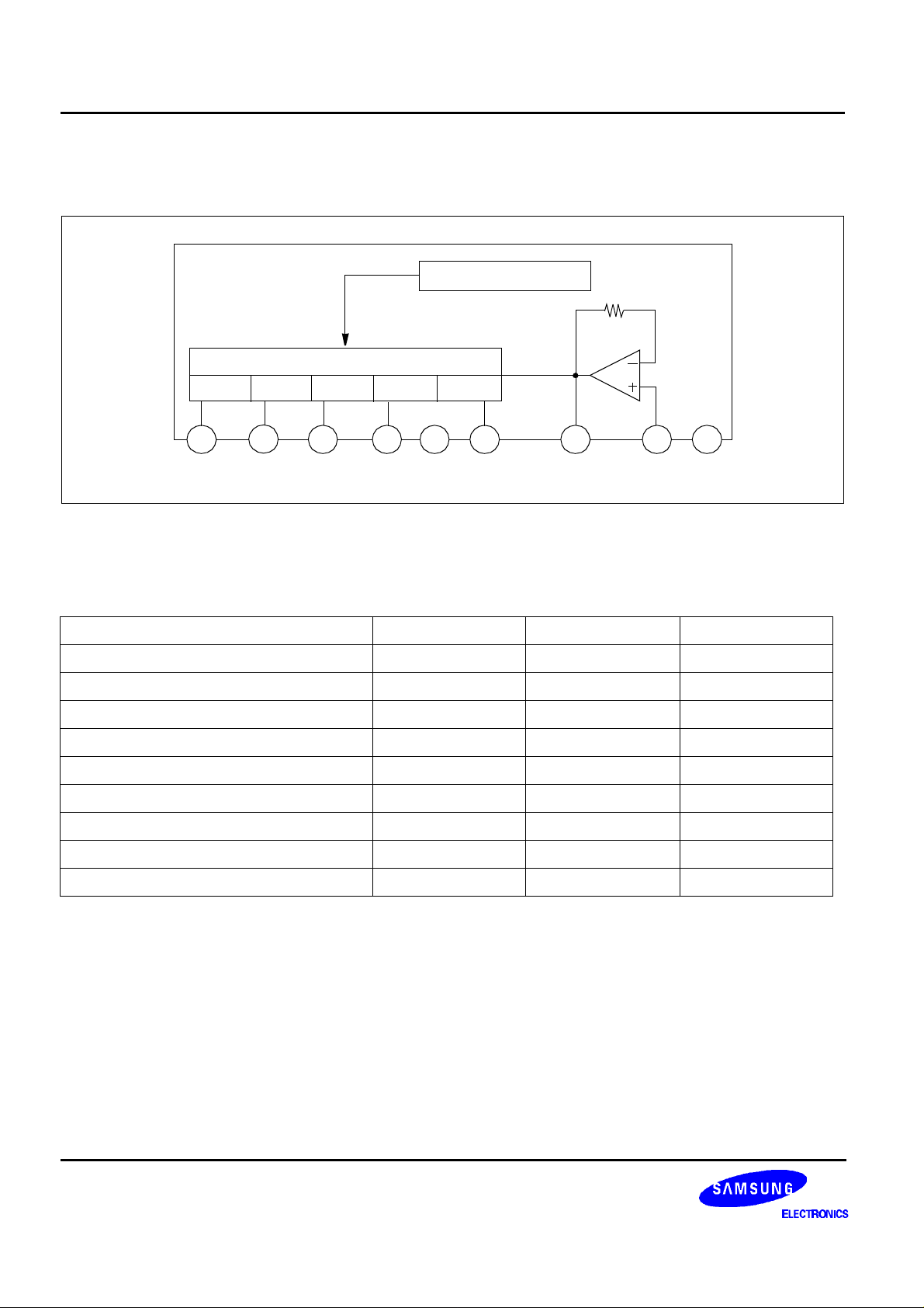
BLOCK DIAGRAM
REFERENCE VOLTAGE
LED DRIVER
D3D2D1
D4
D5
1
D1
NOTE: Capacitor to be omitted when used as a DC input signal meter
2 3 4 5
D2 D3 D4 GND D5 OUTPUT INPUT Vcc
ABSOLUTE MAXIMUM RATINGS (Ta = 25°C)
Characteristic Symbol Value Unit
Supply Voltage V
Amp Input Voltage V
Pin 7 Voltage V
D Terminal Output Voltage V
Circuit Current I
D Terminal Output Current I
Power Dissipation P
Operating Temperature T
Storage Temperature T
CC
8-5
7-5
D
CC
D
d
OPR
STG
6
7
8
9
18 V
−0.5 − V
CC
V
6 V
18 V
12 mA
20 mA
1100 mW
−20 − + 80 °C
−40 − + 125 °C
NOTE: 11mW/°C is decreased at higher temperature than Ta = 25°C.
2
Page 3

5 DOT LED LEVEL METER DRIVER S1A2284A01/02
ELECTRICAL CHARACTERISTICS
(Ta = 25°C, V
= 6V, f = 1kHz, unless otherwise specified)
CC
Characteristic Symbol Test Conditions Min. Typ. Max. Unit
Circuit Current I
CCQ
S1A2284A01
D Output Current
S1A2284A02 5 7 9.5
Input Bias Current I
BIAS
Amp Gain G
V
CL(ON)1
V
CL(ON)2
Comparator ON Level V
NOTE: Definition of 0dB: input voltage level when V
CL (ON)
V
CL(ON)3
V
CL(ON)4
V
CL(ON)5
TEST CIRCUIT
I
O
V
CL (ON)3
Vi = 0V − 6 8.5 mA
11 15 18.5
Vi = 0.15V
− −1 − 0 µA
VI = 0.1 V 24 26 28 dB
−12 −10 −8
−6 −5 −4
− − 0 − dB
2.5 3 3.5
5 6 7
turn ON (50mV)
mA
S1A2284A01/02
1 2 3 4 5 6
D1
D2 D3 D4 D5
10k
987
2.2µ
F/16V
INPUT
Ω
C1
10µF/16V
10k
C2
Ω
Vcc
R
C2 : AC in, 2.2µF is used.
DC in, 2.2µF is shorted.
3
Page 4

S1A2284A01/02 5 DOT LED LEVEL METER DRIVER
The recommended value of R at Ta (max) = 60°C.
VCC (V) 8 − 12 10 −14 12 − 16
R(Ω) 47 68 91
By changing the time constant C1 and C2, the response, attack and release time may be varied. In the above application conditions, power dissipation may be operated at higher levels than the absolute maximum ratings.
The wattage of R is to be determined by the total LED current and R value recommended by the R table.
4
 Loading...