

Page 1
LOW PROFILE HIGH
RP-RELA YS
10.6
.417
9
.748
4
.157
mm inch
FREQUENCY RELAY
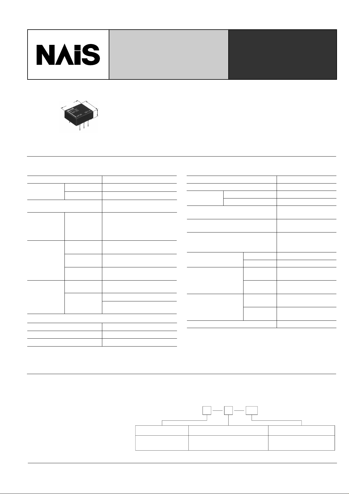
• High frequency relay with the low profile of 4 mm .157 inch
• Excellent high frequency characteristics
Isolation: Min. 10dB (at 1.8 GHz)
Insertion loss: Max. 1.0dB (at 1.8 GHz)
V.S.W.R.: Max. 1.3 (at 1.8 GHz)
• High sensitivity in small size
Size: 10.6 × 9 × 4 mm .417 × .354 × .157 inch
Nominal operating power: 140 mW
SPECIFICATIONS
Contact
Arrangement
Contact material
Initial contact resistance, max.
(By voltage drop 6 V DC 0.1 A)
Rating
High frequency
characteristics
(
Impedance 50Ω
Expected life
(min. operations)
Movable
Stationary
Nominal switching capacity
Isolation
Insertion loss
)
V.S.W.R.
Mechanical
(at 180 cpm)
Electrical
(at 20 cpm)
Coil (at 25°C, 68°F)
Voltage type
1.5 to 12 V DC
24 V DC
1 Form C
Silver alloy
Gold-clad silver
50 mΩ
Contact switching power: 1 W
(Max. 1.8 GHz); Contact carrying
power: 3 W (Max. 1.2 GHz)
1 W (Max. 1.8 GHz)
0.1 A 30 V DC
Min. 15 dB (at 1 GHz)
Min. 10 dB (at 1.8 GHz)
Max. 0.5 dB (at 1 GHz)
Max. 1 dB (at 1.8 GHz)
Max. 1.2 (at 1 GHz)
Max. 1.3 (at 1.8 GHz)
6
5×10
105 (0.1 A 30 V DC)
105 (1 W at 1.8 GHz;
V.S.W.R.: max. 1.3)
Nominal operating power
140 mW
270 mW
Characteristics
Max. operating speed (at rated load)
Initial insulation resistance*
Initial breakdown
2
voltage
*
Operate time*3 (at nominal voltage)
Release time(without diode)*
(at nominal voltage)
Temperature rise
Shock resistance
Vibration
resistance
Conditions for operation,
transport and storage
(Not freezing and condensing
at low temperature)
Unit weight
Remarks
* Specifications will vary with foreign standards certification ratings.
1
Measurement at same location as “Initial breakdown voltage” section
*
2
Detection current: 10mA
*
3
Excluding contact bounce time
*
4
Half-wave pulse of sine wave: 11ms, detection time: 10µs
*
5
Half-wave pulse of sine wave: 6ms
*
6
Detection time: 10µs
*
Between open contacts
Between contacts and coil
1
3
Functional*
Destructive*
Functional*
Destructive
Ambient temp.
Humidity
4
5
6
Min. 1,000 MΩ at 500 V DC
Max. 50°Cwith nominal coil
voltage across coil and at
nominal switching capacity
at double amplitude of 3 mm
at double amplitude of 5 mm
20 cpm
750 Vrms for 1 min.
1,500 Vrms for 1 min.
Max. 3 ms
(Approx. 1.5 ms)
Max. 2 ms
(Approx. 1 ms)
Min. 500 m/s
Min. 1,000 m/s2 {100 G}
10 to 55 Hz
10 to 55 Hz
–40°C to 70°C
–40°F to 158°F
5 to 85% R.H.
Approx. 1 g .04 oz
2
{50 G}
TYPICAL APPLICATIONS
• Antenna switching of mobile phone
• Switching signal of measuring equipment
ORDERING INFORMATION
1Ex. RP H
Contact arrangement
1:1 Form C
Note: Standard packing; Carton: 50 pcs. Case 1,000 pcs.
Terminal shape Coil voltage (DC)
Nil: Standard PC board terminal
H: Self-clinching terminal
3V
1.5, 3, 4.5, 5, 6, 9, 12, 24 V
93
Page 2
RP
TYPES ANE COIL DATA
Part No.
Standard PC
board terminal
Self-clinching
terminal
RP1-1.5V RP1-H-1.5V
RP1-3V RP1-H-3V
RP1-4.5V RP1-H-4.5V
RP1-5V RP1-H-5V
RP1-6V RP1-H-6V
RP1-9V RP1-H-9V
RP1-12V RP1-H-12V
RP1-24V RP1-H-24V
Nominal
voltage,
(at 20°C 68°F)
Pick-up
V DC
12
24
voltage, max.
1.5
3
4.5
5
6
9
18
V DC
1.125
2.25
3.375
3.75
4.5
6.75
9
Drop-out
voltage, min.
V DC
0.15
0.3
0.45
0.5
0.6
0.9
1.2
2.4
Coil
resistance,
Ω (±10%)
16
64.3
145
178
257
579
1,028
2,133
Nominal
operating
current,
mA (±10%)
93.8
46.7
31.1
28
23.3
15.6
11.7
11.3
Nominal
operating
power,
mW
140
140
140
140
140
140
140
270
Maximum.
allowable
voltage,
V DC
2.25
4.5
6.75
7.5
9
13.5
18
28.8
DIMENSIONS
Standard PC board terminal PC board pattern (Copper-side view)
3.75
.157
3.5
.138
4
.148
(0.25)
(.010)
2.54
.100
10.6
.417
0.5
.020
2.54
.100
.354
7.62
.300
9
0.25
.010
Self-clinching terminal
3.75
.157
3.5
.138
4
.148
(0.25)
(.010)
2.54
.100
10.6
.417
0.5
.020
2.54
.100
.354
7.62
.300
9
0.25
.010
Schematic (Bottom view)
General tolerance: ±0.3 ±.012
5.08
.200
6-1 dia.
6-.039 dia.
Tolerance: ±0.1 ±.004
123
–+
654
Direction indication
Deenergized condition
REFERENCE DATA
Sample: RP1-6V
Measuring method: Impedance 50 Ω
Measuring tool:
6–1.60 dia
6–1.00 dia
.039 dia
18.00
.709
0.60
.024
7.62
.300
.063 dia
18.92
.745
1.94
.076
6–2.30 dia
.090 dia
5.08
.200
Soldering
SMA connector
26–0.80 dia
.031 dia
4.22
9.82
.166
.387
mm inch
PC board
• Double-sided through hole
• Material: Glass-epoxy resin
• t= 1.0mm .039 inch
• Copper plated thickness: 35 µm
• Insertion loss • Return loss • V.S.W.R
1. High frequency characteristics
• Isolation
100
90
80
70
60
50
Isolation, dB
40
30
20
10
0
2.54
.100
7.62
.300
0.80 0.4 1.0
Frequency, GHz
mm inch
1.61.41.20.60.2 2.0
1.8
5
4
3
2
Insertion loss, dB
1
0
94
N.O. (Terminal Nos. 5-6)
N.C. (Terminal Nos. 4-5)
0.80 0.4 1.0
Frequency, GHz
1.81.61.41.20.60.2 2.0
100
90
80
70
60
50
Return loss, dB
40
30
20
10
0
0 0.2 0.4 0.6 0.8 1.0 1.2 1.4 1.6 1.8 2.0
N.O. (Terminal Nos. 5-6)
N.C. (Terminal Nos. 4-5)
Frequency, GHz
3.0
2.8
2.6
2.4
2.2
2.0
V.S.W.R.
1.8
1.6
1.4
1.2
1.0
0 0.2 0.4 0.6 0.8 1.0 1.2 1.4 1.6 1.8 2.0
Frequency, GHz
N.C.
N.O.
Page 3
2. Coil temperature rise
Sample: RP1-6V; No. of samples: n = 5
Carrying current: 0.1 A
Ambient temperature: 25°C 77°F
100
90
80
70
60
50
40
Temperature rise, °C
30
20
10
0
80 100 120 150
Coil applied voltage, %V
4. Mechanical life
Sample: RP1-5V; No. of samples: n = 8
• Change of pick-up, drop-out voltage
12
10
8
3. Operate/release time
Sample: RP1-9V; No. of samples: n = 50
• With diode
12
10
8
6
Time, ms
4
2
0
70 80 100 120 150
Coil applied voltage, %V
Operate time
Release time
Max.
Max.
Min.
Min.
5. Electrical life (0.1 A 30 V DC)
Sample: RP1-6V; No. of samples: n = 6
• Change of pick-up/drop-out voltage
12
10
8
• Without diode
12
10
8
6
Time, ms
4
2
Max.
Min.
Max.
Min.
0
70 80 100 120 150
Coil applied voltage, %V
• Change of contact resistance
120
100
80
Operate time
Release time
RP
6
4
Pick-up/drop-out voltage, V
2
Pick-up voltage
Drop-out voltage
100 1,00050050
No. of operations, ×10
Max.
Min.
Max.
Min.
4
6. Ambient temperature characteristics
Sample: RP1-6V; No. of samples: n = 5
40
Drop-out
voltage
20
Rate of change, %
–40 –20 02040 60 80
–20
–40
Pick-up
voltage
Ambient
temperature, °C
8.-(1) Influence of adjacent mounting
Sample: RP1-12V; No. of samples: n = 6
6
Pick-up voltage
4
Pick-up/drop-out voltage, V
2
Drop-out voltage
No. of operations, ×10
Max.
Min.
Max.
Min.
4
7. Contact resistance distribution (initial)
Sample: RP1-6V; No. of samples: n = 25
50
40
30
Quantity
20
10
0
2824 30
Contact resistance, mΩ
383634322622 40
8.-(2) Influence of adjacent mounting
Sample: RP1-12V; No. of samples: n = 6
60
40
Contact resistance, mΩ
20
3020100
No. of operations, ×10
Max.
Min.
3020100
4
8.-(3) Influence of adjacent mounting
Sample: RP1-12V; No. of samples: n = 6
5
0
–5
5
0
–5
Rate of change, % Rate of change, %
0
Inter-relay distance, (mm, inch)
Pick-up voltage
Drop-out voltage
5
.197
10
.394
OFF
OFF
ON
ON
OFF
ON
5
0
–5
5
0
–5
Rate of change, % Rate of change, %
0
Inter-relay distance, (mm, inch)
Pick-up voltage
Drop-out voltage
5
.197
10
.394
OFF OFF
OFF
ON ON
ON
5
0
–5
5
0
–5
Rate of change, % Rate of change, %
0
Inter-relay distance, (mm, inch)
Pick-up voltage
Drop-out voltage
5
.197
10
.394
OFF
ON
95
Page 4
RP
9. High frequency switching test (1.2 GHz, 1 W)
Sample: RP1-6V; No. of samples: n = 6
Ambient temperature: 20°C 68°F
• Change of pick-up/drop-out voltage
• Change of contact resistance
Transmission
RP relay
T1 T2
T1
T2
ON
0.2s 0.2s
1.5s 1.5s
Dummy load (50Ω)
WD-2351
Transmission: RF Tranceiver
IC-1201 (ICOH)
OFF
NOTES
1. Packing direction
Relays are packed in a tube with the orientation stripe (PIN NO. 1) toward the
green stopper.
Orientation (indicates PIN No. 1) stripe
Stopper (green)
2. Automatic mounting
To maintain the internal function of the
relay, the chucking pressure should
not exceed the values below.
Chucking pressure* in the direction A:
4.9 N {500 gf} or less
12
10
8
6
4
Pick-up/drop-out voltage, V
2
Pick-up voltage
Drop-out voltage
No. of operations, ×10
Max.
Min.
Max.
Min.
4
Chucking pressure* in the direction B:
9.8 N {1 kgf} or less
Chucking pressure* in the direction C:
9.8 N {1 kgf} or less
Please chuck the portion.
Avoid chucking the center of the relay. In
addition, excessive chucking pressure to
the pinpoint of the relay should be avoided.
CB
A
(4)
(5)
(6)
*Value of chucking pressure is shown by the value of weight
pressed on the portion (4 mm .157 inch dia.).
• Direction A • Direction B • Direction C
3
2
1
mm inch
546
3
.118
6
.236
23
1
120
100
80
60
40
Contact resistance, mΩ
20
151050
No. of operations, ×10
3. Soldering
Preheat according to the following conditions.
Temperature 100°C 212°F or less
Time Within 1 minute
Soldering should be done at 250°C
482°F within 5 s.
Max.
Min.
151050
4
For Cautions for Use, see Relay Technical Information (Page 48 to 76).
96
9/1/2000 All Rights Reserved, © Copyright Matsushita Electric Works, Ltd.
Go To Online Catalog
 Loading...