

Page 1
97
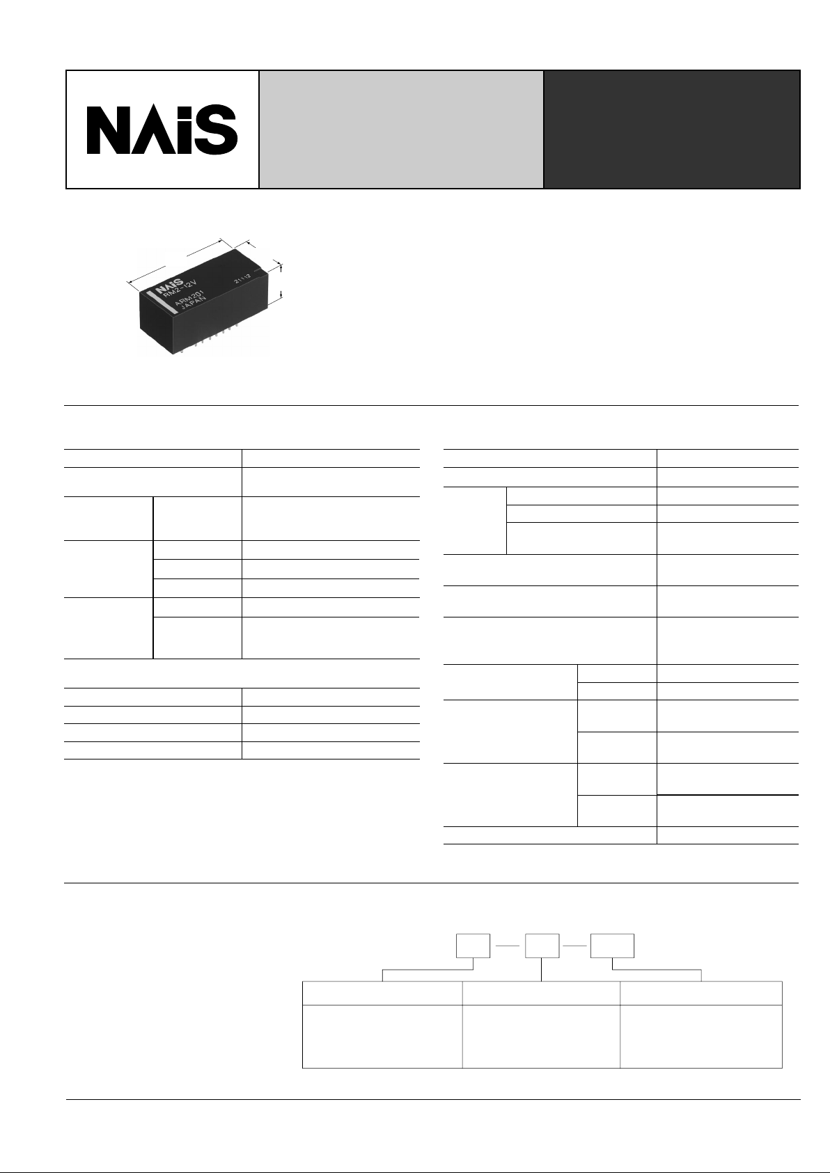
4 GHz 2 FORM C
MICROWAVE RELAY
RM-RELA YS
12.4
.488
10.5
.413
28
1.102
2Ex. RM L2
Contact arrangement
2:2 Form C
Note: Standard packing; Carton: 20 pcs. Case 200 pcs.
Nil: Single side stable
L: 1 coil latching
L2: 2 coil latching
3, 4.5, 5, 6, 9, 12, 24 V
Operating function Coil voltage (DC)
24V
Arrangement
Initial contact resistance, max.
(By HP4328A)
Rating
Nominal switching capacity
Isolation
Insertion loss
V.S.W.R.
Mechanical
Electrical
(at 20 cpm)
Min. 40 dB (at 4 GHz)
Max. 1.0 dB (at 4 GHz)
Max. 1.5 (at 4 GHz)
5×10
6
3×10⁵ (0.01 A 24 V DC)
1×10⁵
(10 W at 1.2 GHz, Impedance 50Ω)
High frequency
characteristics
(
Impedance 50Ω
)
Expected life
(min. operations)
Contact
Coil (at 25°C, 68°F)
2 coil latching
Single side stable 360 mW
Nominal operating power
1 coil latching
500 mW
250 mW
2 Form C
100 mΩ
0.01 A 24 V DC
10 W
(at 1.2 GHz, Impedance 50Ω)
Max. operating speed (at rated load)
Characteristics
20 cpm
Initial insulation resistance*
1
Operate time [Set time]*3 (at nominal voltage)
Approx. 6 ms
[Approx. 3ms]
Max. 60°C with nominal coil
voltage across coil and at
nominal switching capacity
Temperature rise
Initial
breakdown
voltage*
2
Between open contacts
Between contact and coil
Between contact and
earth terminal
500 Vrms for 1 min.
1,000 Vrms for 1 min.
500 Vrms for 1 min.
Min. 100 MΩ at 500 V DC
Shock resistance
Vibration
resistance
Unit weight
Remarks
*
Specifications will vary with foreign standards certification ratings.
*
1
Measurement at same location as “Initial breakdown voltage” section
*
2
Detection current: 10mA
*
3
Excluding contact bounce time
*
4
Half-wave pulse of sine wave: 11ms, detection time: 10µs
*
5
Half-wave pulse of sine wave: 6ms
*
6
Detection time: 10µs
Approx. 7 g .247 oz
Min. 98 m/s
2
{10 G}
Min. 980 m/s2 {100 G}
Functional*
4
Destructive*
5
Functional*
6
Destructive
10 to 55 Hz
at double amplitude of 1.5 mm
10 to 55 Hz
at double amplitude of 2 mm
Conditions for operation,
transport and storage
(Not freezing and condensing
at low temperature)
Ambient temp.
Humidity
–40°C to 60°C
–40°F to 140°F
5 to 85% R.H.
Release time (without diode)[Reset time]*
3
(at nominal voltage)
Approx. 3 ms
[Approx. 3ms]
TYPICAL APPLICATIONS
• Measuring equipment (Attenuator circuits)
• Audio visual equipment
• Communication equipment
ORDERING INFORMATION
• Excellent high frequency characteristics
Isolation: Min. 40dB (at 4 GHz)
Insertion loss Max. 1.0dB (at 4 GHz)
V.S.W.R.: Max. 1.5 (at 4 GHz)
• High sensitivity in small size
Size: 28.0 × 12.4 × 10.5 mm 1.102 × .488 × .413 inch
Nominal operating power: 360 mW (single side stable type)
• Sealed construction for automatic cleaning
• Latching types are also available
SPECIFICATIONS
mm inch
Page 2
98
RM
2 coil latching
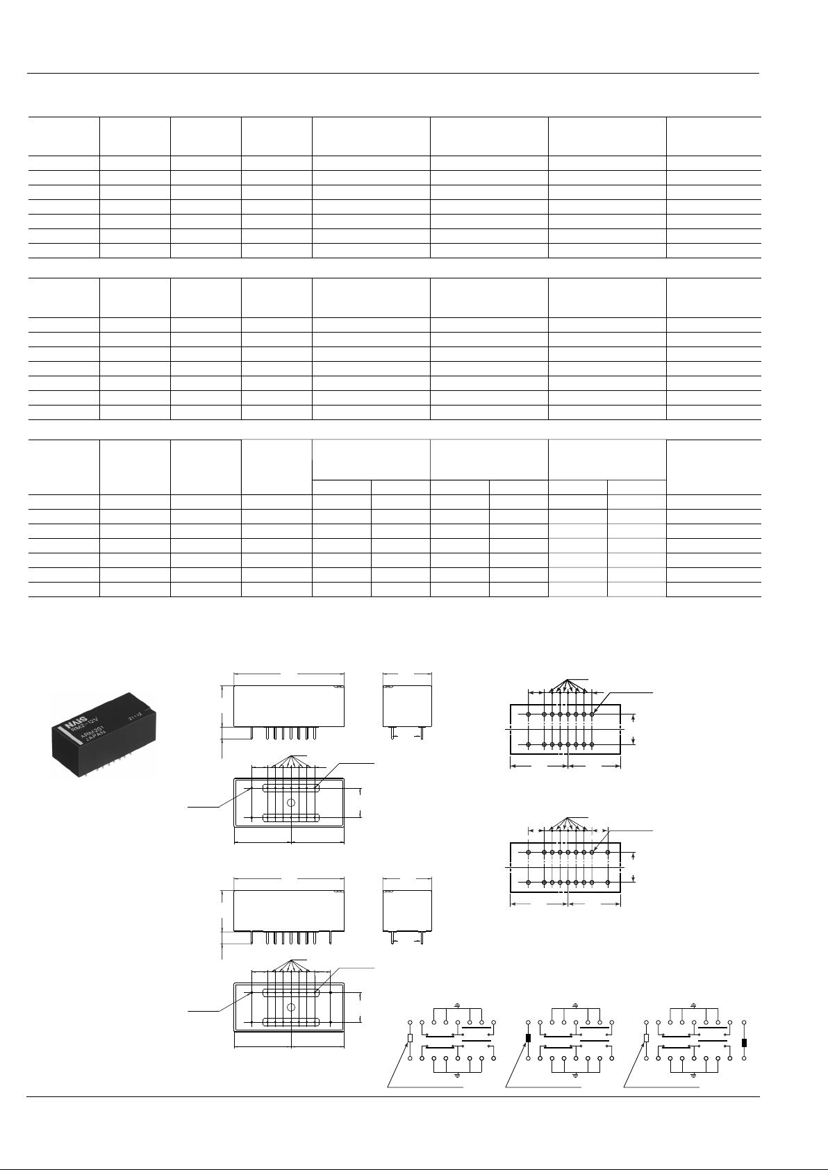
Schematic (Bottom view)
Tolerance: ±0.3 ±.012
General tolerance: ±0.3 ±.012
2
.079
18-1.0 dia.
18-.039dia.
3
.118
2
.079
2 coil latching
4-❏ 0.45
4-❏ .018
14-0.45 dia.
14-.018 dia.
4
.157
4
.157
2 coil latching
(Reset condition)
+
−
Set
Reset
COM
COM
+
−
Direction indication
14.5
.571
13.5
.531
7.5
.295
4
.157
2
.079
16-1.0 dia.
16-.039dia.
Single side stable and 1coil latching
PC board pattern (Bottom view)
mm inch
14.5
.571
13.5
.531
7.5
.295
4
.157
2
.079
16-1.0 dia.
16-.039dia.
1 coil latching
(Reset condition)
RESET
RESET
RESET
RESET
SET
SET
SET
SET
COM
COM
+
−
Direction indication
4
.157
3
.118
2
.079
2-❏ 0.45
2-❏ .018
14-0.45 dia.
14-.018 dia.
14.5
.571
13.5
.531
14.5
.571
13.5
.531
Single side stable and 1 coil latching
Single side stable
(Deenergized condition)
N.C. N.O.
N.O.
COM
N.C.
COM
+
−
Direction indication
12.4
.488
7.5
.295
28
1.102
10.5
.413
7.5
.295
4
.157
4
.157
7.5
.295
14.5
.571
13.5
.531
28
1.102
10.5
.413
12.4
.488
7.5
.295
7.5
.295
Part No.
RM2-3V 3 2.25 0.3 25 120 360 3.3
4.5 3.375 0.45 56 80 360 4.95
5 3.75 0.5 69 72 360 5.5
6 4.5 0.6 100 60 360 6.6
9 6.75 0.9 225 40 360 9.9
24 18 2.4 1,600 15 360 26.4
RM2-4.5V
RM2-5V
RM2-6V
RM2-9V
12 9 1.2 400 30 360 13.2RM2-12V
RM2-24V
Nominal
voltage,
V DC
Pick-up
voltage,
max. V DC
Drop-out
voltage,
min. V DC
Coil resistance,
Ω (±10%)
Nominal
operating
current, mA
Nominal
operating power,
mW
Max. allowable
voltage, V DC
(at 60°C 140°F)
• Single side stable type
Part No.
RM2-L-3V 3 2.25 36 83.3 250 3.3
4.5 3.375 81 55.6 250 4.95
5 3.75 100 50 250 5.5
6 4.5 144 41.7 250 6.6
9 6.75 324 27.8 250 9.9
24 18 2,304 10.4 250 26.4
RM2-L-4.5V
RM2-L-5V
RM2-L-6V
RM2-L-9V
12 9 576 20.8 250 13.2RM2-L-12V
RM2-L-24V
Nominal
voltage,
V DC
Set voltage,
max. V DC
Reset
voltage,
max. V DC
Set voltage,
max. V DC
Reset
voltage,
max. V DC
Set coil Reset coil Set coil Reset coil Set coil Reset coil
Coil resistance,
Ω (±10%)
Nominal
operating current,
mA (±10%)
Nominal
operating power,
mW
Max. allowable
voltage, V DC
(at 60°C 140°F)
• 1 coil latching type
Part No.
RM2-L2-3V 3 2.25 3.3
4.5 3.375 4.95
5 3.75 5.5
6 4.5 6.6
9 6.75 9.9
24 18 26.4
RM2-L2-4.5V
RM2-L2-5V
RM2-L2-6V
RM2-L2-9V
12 9
2.25
3.375
3.75
4.5
6.75
18
9
2.25
3.375
3.75
4.5
6.75
18
9 13.2
18
40.5
50
72
162
1,152
288
18
40.5
50
72
162
1,152
288
166.7
111.1
100
83.3
55.6
20.8
41.7
166.7
111.1
100
83.3
55.6
20.8
41.7
500
500
500
500
500
500
500
500
500
500
500
500
500
500RM2-L2-12V
RM2-L2-24V
Nominal
voltage,
V DC
Coil resistance,
Ω (±10%)
Nominal
operating current,
mA (±10%)
Nominal
operating power,
mW
Max. allowable
voltage, V DC
(at 60°C 140°F)
• 2 coil latching type
TYPES ANE COIL DATA (at 20°C 68°F)
DIMENSIONS
Page 3

99
RM
30
1.181
23.5
.925
7.5
.295
2.5
.098
2.5
.098
20
.787
12
.472
8
.315
4
.157
8
.315
2
.079
3
.118
45°
(Wiring diagram)
1 dia.
.039 dia.
1 dia.
.039 dia.
2 dia.
.079 dia.
0.8 dia.
.031 dia.
Tolerance: ±0.1 ±.004
PC board
• Double-sided through hole
• Material: Glass-PTFE
mm inch
10
20
30
40
50
60
70
80
90
100
102345
Frequency, GHz
Isolation, dB
1
0
2
3
4
5
102345
Frequency, GHz
Insertion loss, dB
1.1
1.0
1.2
1.3
1.4
1.5
1.6
1.7
1.8
1.9
2.0
102345
Frequency, GHz
V.S.W.R.
0
20
40
60
80
100
80 100 120 140 150
Coil applied voltage, %V
Temperature rise, °C
0
2
4
6
8
10
80 100 120 140 150
Coil applied voltage, %V
Max.
Min.
Min.
Max.
Operate time
Release time
Operate/Reset time, ms
0
2
4
6
8
10
80 100 120 140 150
Coil applied voltage, %V
Max.
Min.
Max.
Min.
Set/Reset time, ms
Set time
Reset time
0
10
20
30
40
50
60
70
80
90
100
Min.
Max.
Min.
Max.
10 100 1,000
No. of operations, ×10
4
Ratio against the rated voltage, %V
Pick-up voltage
Drop-out voltage
0
10
20
30
40
50
60
70
80
90
100
Min.
Max.
Min.
Max.
10 20 30
No. of operations, ×10
4
Ratio against the rated voltage, %V
Pick-up voltage
Drop-out voltage
0
10
20
30
40
50
60
70
80
90
100
Min.
Max.
10 20 30
No. of operations, ×10
4
Contact resistance, mΩ
1. High frequency characteristics
Sample: RM2-12V
Measuring method: Impedance 50 Ω
REFERENCE DATA
• Isolation • Insertion loss
• V.S.W.R.
2. Coil temperature rise
Sample: RM2-12V; No. of samples: n = 5
Carrying current: 10 mA
Point measured: Inside the coil
Ambient temperature: 27 to 28°C 80.6 to 82.4°F
3.-(1) Operate/Release time
(Single side stable)
Sample: RM2-12V; No. of samples: n = 6
3.-(2) Set/Reset time (Latching)
Sample: RM2-L2-5V
No. of samples: n = 5
4. Mechanical life test
Sample: RM2-12V; No. of samples: n = 10
5. Electrical life test (0.01 A 24 V DC)
Sample: RM2-5V; No. of samples: n = 6
Change of pick-up and drop-out voltage
Change of contact resistance
Page 4

100
RM
40
–40
–40
–20–40
32
40
1046014080176
–10
–20
–30
–40
30
20
10
20
68
Ambient
temperature, °C, °F
Rate of
change, %
Mean value
Mean value
Drop-out voltage
Pick-up
voltage
0
10
20
30
40
50
30 40 50 60
Contact resistance, mΩ
Quantity
ON
ON condition
OFF
OFF
OFF condition
–10
10
–10
10
05
.19710.39415.59120.787
Inter-relay distance, (mm, inch)
Rate of change, % Rate of change, %
Pick-up voltage
Drop-out voltage
–10
0
10
–10
0
10
05
.19710.39415.59120.787
ON ON
ON
OFF OFF
OFF
Inter-relay distance, (mm, inch)
Rate of change, % Rate of change, %
Pick-up voltage
Drop-out voltage
6. Ambient temperature characteristics
Sample: RM2-12V; No. of samples: n = 5
7. Contact resistance distribution (initial)
Sample: RM2-12V
No. of samples: n = 50 (50 × 4 contacts)
8.-(1) Influence of adjacent mounting
8.-(2) Influence of adjacent mounting
NOTE
1. Soldering
Soldering should be done under the following conditions.
Temperature 260°C 500°F 350°C 662°F
Time
Within
10 s
Within
3 s
For Cautions for Use, see Relay Technical Information (Page 48 to 76).
9/1/2000 All Rights Reserved, © Copyright Matsushita Electric Works, Ltd.
Go To Online Catalog
 Loading...