

Page 1
105
Arrangement
Contact
Coil (polarized) (at 25°C, 68°F)
1 Form C 2 Form C
Single side stable
350 mW 400 mW
1 coil latching
175 mW 200 mW
2 coil latching
350 mW 400 mW
1 Form C, 2 Form C
Contact material
Initial contact resistance, max.
(By voltage drop 6 V DC 1 A)
High frequency characteristics
(at 900 MHz)
Gold-clad silver
100 mΩ
24 W
24 V DC
1 A
1 A 24 V DC
5×10
6
10
5
Min. 65 dB Min. 65 dB
75 Ω50 Ω
Max. 1 dB Max. 1 dB
Max. 1.2
Isolation
Insertion loss
V.S.W.R. Max. 2.0
Initial insulation resistance*
1
Shock resistance
Vibration resistance
Unit weight
Ambient
temp.
Humidity 5 to 85%R.H.
Characteristics
Min. 100 MΩ at 500 V DC
Operate time*3 (at nominal voltage)
Approx. 10 ms
Release time*3 (at nominal voltage)(without diode)
Temperature rise (at 20°C)
Approx. 5 ms
Set time*
3
(at nominal voltage)
Approx. 7 ms
Reset time*
3
(at nominal voltage)
Approx. 7 ms
Max. 55°C with nominal coil voltage
across coil and at nominal switching capacity
Functional*
4
Destructive*
5
Functional*
6
1 C type
2 C type
Approx. 8 g .282 oz
Approx. 10 g .353 oz
Destructive
Min. 196 m/s
2
{20 G}
Min. 980 m/s2 {100 G}
10 to 55 Hz
at double amplitude of 2 mm
10 to 55 Hz
at double amplitude of 2 mm
–50°C to 60°C
–58°F to 140°F
Rating
(resistive)
Max. switching power
Max. switching voltage
Max. switching current
Nominal switching capacity
Initial
breakdown
voltage*
2
Between open contacts
Between contacts and coil
Between contacts and
earth terminal
1,000 Vrms
2,000 Vrms
500 Vrms
Expected life
(min. operations)
Mechanical
Electrical 1 A 24 V DC
Conditions for operation,
transport and storage
(Not freezing and condensing at low temperature)
Remarks
* Specifications will vary with foreign standards certification ratings.
*
1
Measurement at same location as “Intial breakdown voltage” section
*
2
Detection current: 10mA
*
3
Excluding contact bounce time
*
4
Half-wave pulse of sine wave: 11ms; detection time: 10µs
*
5
Half-wave pulse of sine wave: 6ms
*
6
Detection time: 10µs
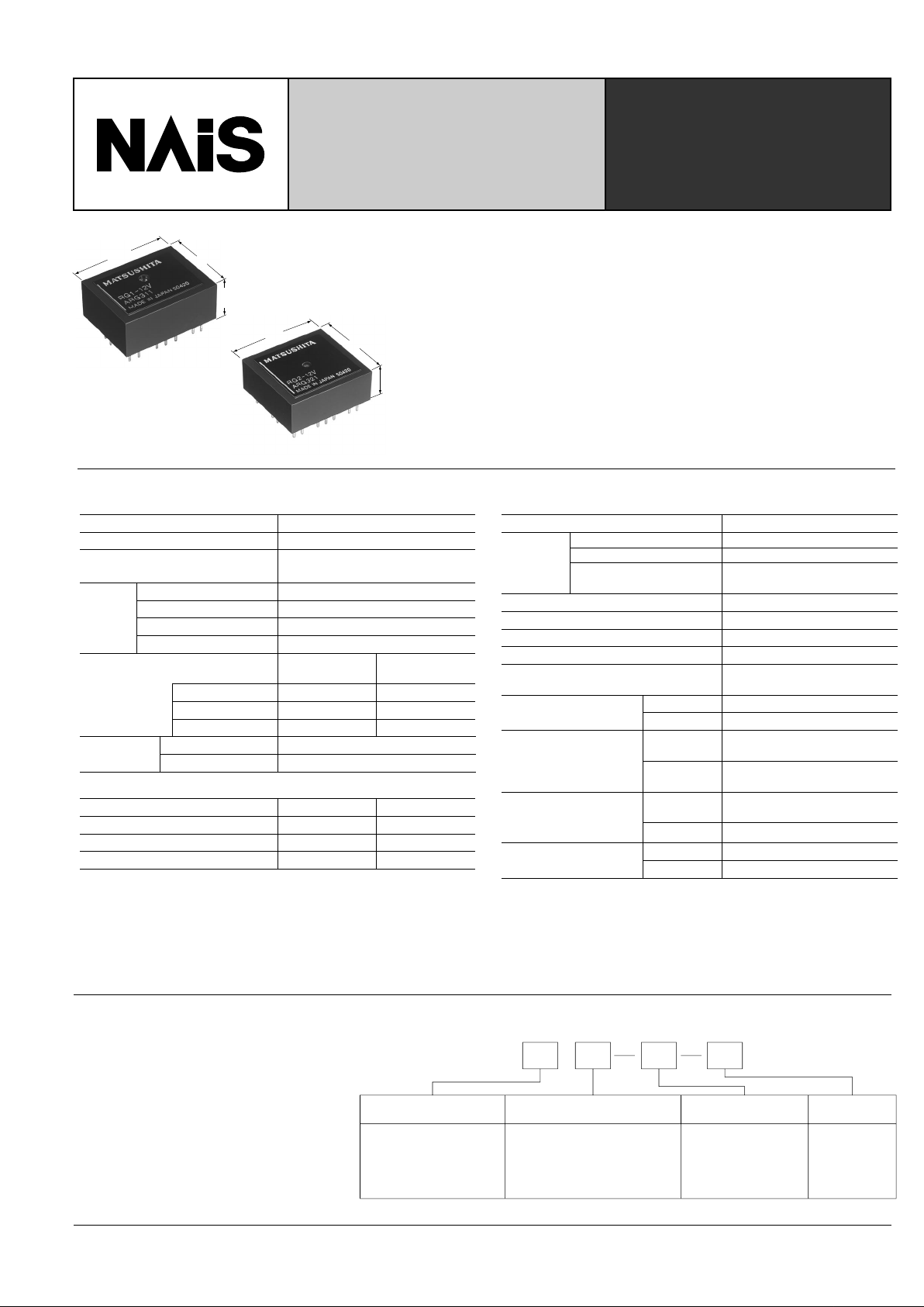
HIGH FREQUENCY
RG RELAYS WITH 1C
AND 2C CONTACTS
RG-RELA YS
19
.748
10.4
.409
25
.984
1 Form C
23
.906
9.9
.390
25
.984
2 Form C
mm inch
1T L 5VEx. RG
Contact arrangement Characteristic impedance Operating function Coil voltage
1:1 Form C
2:2 Form C
Note: Standard packing; Carton: 50 pcs. Case 500 pcs.
Nil: 75 Ω
T: 50 Ω
Nil: Single side
Nil: stable
L: 1 coil latching
L2: 2 coil latching
DC: 3, 5, 6,
9, 12, 24,
48 V
TYPICAL APPLICATIONS
• Measuring instrument
• T esting equipment
• CATV converter
• Audio visual equipment
• TV game set
ORDERING INFORMATION
• Excellent high frequency characteristics
Isolation: Min. 65dB (at 900 MHz)
Insertion loss: Max. 1.0 (at 900 MHz)
• Wide selection
Characteristic impedance: 50 Ω type and 75 Ω type
Coil: Single side stable and latching type
• 1 A 24 V DC switching capacity
• Sealed construction for automatic cleaning
• High sensitivity 350W (1 Form C) in small size
SPECIFICATIONS
Page 2
106
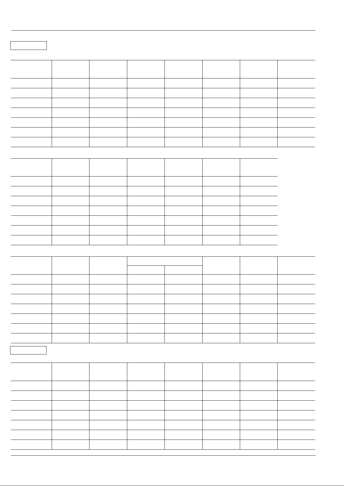
Part No.
Nominal
voltage
V DC
RG1-3V
RG1T-3V
RG1-5V
RG1T-5V
RG1-6V
RG1T-6V
RG1-9V
RG1T-9V
RG1-12V
RG1T-12V
RG1-24V
RG1T-24V
RG1-48V
RG1T-48V
Pick-up
voltage, max.
V DC
Drop-out
voltage, min.
V DC
Coil
resistance,
Ω (±10%)
Nominal
operating
current, mA
Nominal
operating
power, mW
Maximum
allowable
voltage, V DC
(40°C 104°F)
Single side stable
3
5
6
9
12
24
48
2.4
4.0
4.8
7.2
9.6
19.2
38.4
0.3
0.5
0.6
0.9
1.2
2.4
4.8
25.7
71.4
103
231
411
1,646
6,583
117.3
70.3
58.3
38.9
29.2
14.6
7.3
350
350
350
350
350
350
350
3.6
6.0
7.2
10.8
14.4
28.8
57.6
Part No.
Nominal
voltage
V DC
RG1-L-3V
RG1T-L-3V
RG1-L-5V
RG1T-L-5V
RG1-L-6V
RG1T-L-6V
RG1-L-9V
RG1T-L-9V
RG1-L-12V
RG1T-L-12V
RG1-L-24V
RG1T-L-24V
RG1-L-48V
RG1T-L-48V
Set and reset
voltage,
V DC (max.)
Coil
resistance,
Ω (±10%)
Nominal
operating
current, mA
Nominal
operating
power, mW
Maximum
allowable
voltage, V DC
(40°C 104°F)
1 coil latching
3
5
6
9
12
24
48
2.4
4.0
4.8
7.2
9.6
19.2
38.4
51.4
142.8
206.8
462.8
822.8
3,292.8
13,166.8
58.3
35.8
29.2
19.4
14.6
7.3
3.6
175
175
175
175
175
175
175
Part No.
Nominal
voltage
V DC
RG1-L2-3V
RG1T-L2-3V
RG1-L2-5V
RG1T-L2-5V
RG1-L2-6V
RG1T-L2-6V
RG1-L2-9V
RG1T-L2-9V
RG1-L2-12V
RG1T-L2-12V
RG1-L2-24V
RG1T-L2-24V
RG1-L2-48V
RG1T-L2-48V
Set and reset
voltage,
V DC (max.)
Coil 1 Coil 2
Coil resistance, Ω (±10%)
Nominal
operating
current, mA
Nominal
operating
power, mW
Maximum
allowable
voltage, V DC
(40°C 104°F)
2 coil latching
3
5
6
9
12
24
48
2.4
4.0
4.8
7.2
9.6
19.2
38.4
25.7
71.4
103
231
411
1,646
6,583
25.7
71.4
103
231
411
1,646
6,583
117.8
70.8
58.3
38.9
29.2
14.6
7.3
350
350
350
350
350
350
350
3.6
6.0
7.2
10.8
14.4
28.8
57.6
Part No.
Nominal
voltage
V DC
RG2-3V
RG2T-3V
RG2-5V
RG2T-5V
RG2-6V
RG2T-6V
RG2-9V
RG2T-9V
RG2-12V
RG2T-12V
RG2-24V
RG2T-24V
RG2-48V
RG2T-48V
Pick-up
voltage, max.
V DC
Drop-out
voltage, min.
V DC
Coil
resistance,
Ω (±10%)
Nominal
operating
current, mA
Nominal
operating
power, mW
Maximum
allowable
voltage, V DC
(40°C 104°F)
Single side stable
3
5
6
9
12
24
48
2.4
4.0
4.8
7.2
9.6
19.2
38.4
0.3
0.5
0.6
0.9
1.2
2.4
4.8
22.5
62.5
90
202.5
360
1,440
5,760
133.8
80.8
66.7
44.4
33.3
16.7
8.3
400
400
400
400
400
400
400
3.6
6.0
7.2
10.8
14.4
28.8
57.6
3.6
6.0
7.2
10.8
14.4
28.8
57.6
TYPES ANE COIL DATA (at 20°C 68°F)
RG
1 Form C
2 Form C
Page 3
107
Part No.
Nominal
voltage
V DC
RG2-L-3V
RG2T-L-3V
RG2-L-5V
RG2T-L-5V
RG2-L-6V
RG2T-L-6V
RG2-L-9V
RG2T-L-9V
RG2-L-12V
RG2T-L-12V
RG2-L-24V
RG2T-L-24V
RG2-L-48V
RG2T-L-48V
Set and reset
voltage,
V DC (max.)
Coil
resistance,
Ω (±10%)
Nominal
operating
current, mA
Nominal
operating
power, mW
Maximum
allowable
voltage, V DC
(40°C 104°F)
1 coil latching
3
5
6
9
12
24
48
2.4
4.0
4.8
7.2
9.6
19.2
38.4
45
125
180
405
720
2,880
11,520
66.7
40.8
33.3
22.2
16.7
8.3
4.2
200
200
200
200
200
200
200
Part No.
Nominal
voltage
V DC
RG2-L2-3V
RG2T-L2-3V
RG2-L2-5V
RG2T-L2-5V
RG2-L2-6V
RG2T-L2-6V
RG2-L2-9V
RG2T-L2-9V
RG2-L2-12V
RG2T-L2-12V
RG2-L2-24V
RG2T-L2-24V
RG2-L2-48V
RG2T-L2-48V
Set and reset
voltage,
V DC (max.)
Coil 1 Coil 2
Coil resistance, Ω (±10%)
Nominal
operating
current, mA
Nominal
operating
power, mW
Maximum
allowable
voltage, V DC
(40°C 104°F)
2 coil latching
3
5
6
9
12
24
48
2.4
4.0
4.8
7.2
9.6
19.2
38.4
22.5
62.5
90
203
360
1,440
5,760
22.5
62.5
90
202.5
360
1,440
5,760
133.8
80.8
66.7
44.4
33.3
16.7
8.3
400
400
400
400
400
400
400
3.6
6.0
7.2
10.8
14.4
28.8
57.6
3.6
6.0
7.2
10.8
14.4
28.8
57.6
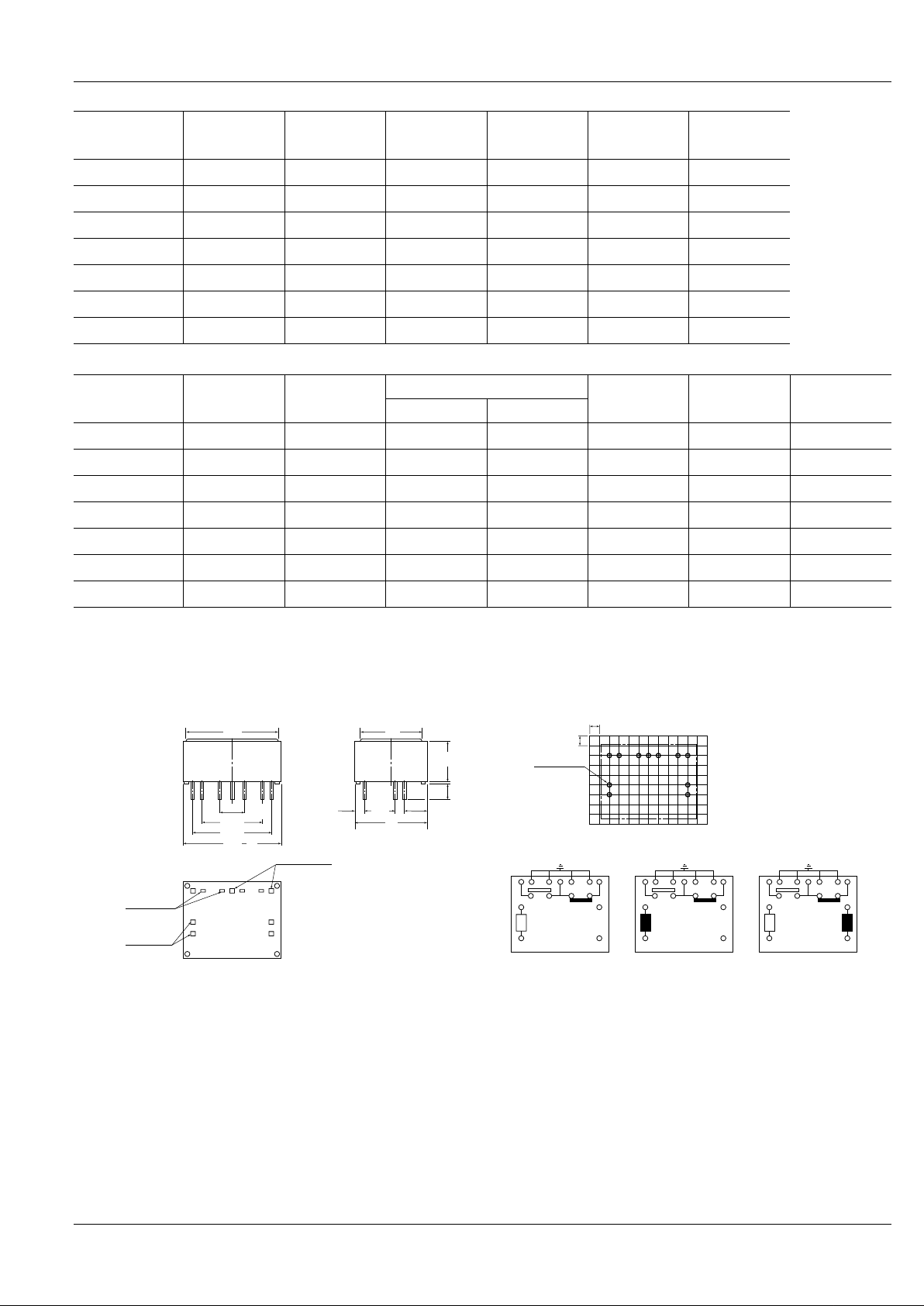
RG
15.24
.600
5.08
.200
7.62
.300
9.9
.390
0.5
.020
3.7
.146
19
.748
2.54
.100
2.61
.103
Tolerance: ±0.3 ±.012
Tolerance: ±0.1 ±.004
Schematic (Bottom view)
Deenergized condition Reset condition Reset condition
Single side stable
PC board pattern (Copper-side view)1 Form C type
1 coil latching 2 coil latching
Set coil
Reset coil
20.32
.800
25
.984
4–0.4×0.25
.016×.010
4–0.4×0.4
.016×.016
3–0.5×0.4
.020×.016
2.54
.100
2.54
.100
11-1 DIA
11-.039 DIA.
1 2 345 6 7
15
–
16
+
–
+
–
+
+
–
17
18
1 2 345 6 7
15
16
17
18
1 2 345 6 7
15
16
17
18
21
.827
15
.591
DIMENSIONS
mm inch
Page 4

108
RG
15.24
.600
5.08
.200
9.4
.370
0.5
.020
3.7
.146
23
.906
17.78
.700
2.54
.100
General tolerance: ±0.3 ±.012
Tolerance: ±0.1 ±.004
Schematic (Bottom view)
Deenergized condition Reset condition Reset condition
Single side stable
PC board pattern (Copper-side view)
2 Form C type
1 coil latching 2 coil latching
20.32
.800
25
.984
8–0.4×0.25
.016×.010
4–0.4×0.4
.016×.016
6–0.5×0.4
.020×.016
2.54
.100
2.54
.100
18-1 DIA
18-.039 DIA.
1 2 345 6 7
8 9
10 11 12 13 14
15
–
16
+
17
18
1 2 345 6 7
8 9
10 11 12 13 14
15
+
16
–
17
18
1 2 345 6 7
8 9
10 11 12 13 14
15
–
16
+
+
–
17
18
Set coil
Reset coil
21
.827
19
.748
mm inch
Isolation, dB
50
100
5000 1000
Frequency, MHz
Isolation, dB
Frequency, MHz
50
100
5000 1000
Frequency, MHz
Isolation, dB
5
0
5000 1000
Frequency, MHz
Insertion loss, dB
0
5
5000 1000
Frequency, MHz
Insertion loss, dB
REFERENCE DATA
1. Isolation
RG2-12V
75 Ω characteristic impedance
RG2T-12V
50 Ω
characteristic impedance
2. Insertion loss
RG2-12V
75 Ω characteristic impedance
RG2T-12V
50 Ω characteristic impedance
Page 5

109
RG
50
100
5000 1000
Frequency, MHz
Return loss, dB
50
100
5000 1000
Frequency, MHz
Return loss, dB
5
10
15
80
0
100 120
Coil voltage, %V
Operate and release time, ms
Max.
Max.
x
x
Min.
Min.
Operate time
Release time
0
5
10
15
80 100 120
Coil voltage, %V
Set and reset time, ms
Max.
Max.
x
x
Min.
Min.
Set time
Reset time
5
10
15
80
0
100 120
Coil voltage, %V
Operate and release time, ms
Max.
Max.
x
x
Min.
Operate time
Release time
Min.
x
x
Max.
Min.
Min.
Max.
Set time
Reset time
5
10
15
80
0
100 120
Coil voltage, %V
Set and reset time, ms
50
100
000.5 1.0 1.5 2.0 2.5
Operate bounce, ms
Frequency
Operate bounce
50
100
00 0.5 1.0 1.5 2.0 2.5
Frequency
Release bounce, ms
Release bounce
50
100
000.5 1.0 1.5 2.0 2.5
Frequency
Set bounce
Set bounce, ms
50
100
000.5 1.0 1.5 2.0 2.5
Frequency
Reset bounce
Reset bounce, ms
3. Return loss
RG2-12V
75 Ω characteristic impedance
RG2T-12V
50 Ω characteristic impedance
4-(1). Operate and release time (1C)
RG1-12V 6 pcs.
4-(2). Set and reset time (1C)
RG1-L2-12V 6 pcs.
4-(3). Operate and release time
(Without diode) (2C)
RG2-12V 6 pcs.
4-(4). Set and reset time (2C)
RG2-L2-12V 6 pcs.
5-(1). Bounce time (2C)
RG2-12V 100 pcs.
Nominal voltage is applied.
5-(2). Bounce time (2C)
RG2-L2-12V 100 pcs.
Nominal voltage is applied.
Page 6

110
RG
500
2
4
6
8
10
100 200 300 4000
Min.
Max.
Min.
Max.
x
x
No. of operations, ×10
4
Pick-up and drop-out voltage
Pick-up voltage
Drop-out voltage
2
4
6
8
10
100 200 300 400 5000
x
x
Max.
Min.
Max.
Min.
No. of operations, ×10
4
Set and reset voltage, V
Set voltage
Reset voltage
40
20
60
80
100
2468100
Min.
Max.
x
No. of operations, ×10
4
Contact resistance, mΩ
20
40
60
80
100
2468100
Min.
Max.
x
No. of operations, ×10
4
Contact resistance, mΩ
–30
–20
–10
0
10
20
30
40
–40 –20 0 20 40 60 80
Ambient temperature, °C
Rate of change, %
Pick-up voltage
Drop-out voltage
–30
–20
–10
0
10
20
30
40
–40 –20 0 20 40 60 80
Ambient temperature, °C
Rate of change, %
Set voltage
Reset voltage
–30
–20
–10
0
10
20
30
40
–40 –20 0 20 40 60 80
Ambient temperature, °C
Rate of change, %
Pick-up voltage
Drop-out voltage
–30
–20
–10
0
10
20
30
40
–40 –20 0 20 40 60 80
Ambient temperature, °C
Rate of change, %
Set voltage
Reset voltage
6-(1). Mechanical life (1C)
RG1-12V 12 pcs.
6-(2). Mechanical life (1C latching type)
RG1-L2-12V 6 pcs.
7-(1). Electrical life (10 mA 24 V DC
resistive load)
RG2-12V 6 pcs.
7-(2). Electrical life (1 A 24 V DC resistive load)
RG2-12V 6 pcs.
8-(1). Rate of change in pick-up and drop-out
voltage (1C)
RG1-12V 5 pcs.
RG1-L2-12V 5 pcs.
8-(2). Rate of change in pick-up and dropout voltage (2C)
RG2-12V 5 pcs.
RG2-L2-12V 5 pcs.
Page 7

111
RG
Spectrum analyzer
Measurement tool
NM type connector
50 Ω or 75 Ω
RG relay
40
1.575
40
1.575
A
70
2.756
1.5 dia.
.059
1.0 dia.
.039
2.5
.098
3.5
.138
70
2.756
PC board pattern
Expanslon of A
(1) Capacitor
Relay
Ry
Capacitor
r
SW
E
(2) Diode
Relay
Ry
Diode
SW
E
Test condition
mm inch
1. Characteristic impedance of all the
measuring devices (signal generator and cable) is 50 Ω or 75 Ω .
2. The PC board for the test is double
side copper clad phenolic paper
laminate with thickness of 1.6 mm.
3. Grounding terminal holes are plated
through.
4. Grounding terminal and one of the
coil terminals are soldered to the PC
board to be grounded.
5. Connection with measurement instrument is made with semi-rigid cable (Uniform Tube UT 141A) and
high frequency NM type connector.
NOTES
1. Soldering
Perform soldering under the conditions below.
• Within 10s at 250°C 482°F
• Within 5s at 300°C 572°F
• Within 3s at 350°C 662°F
2. Counter voltage of DC relays
If input is cut off in DC relays, a
counter voltage is developed across
the coil as a result of the collapse of
the magnetic field. If the coil is used in
a transistor circuit, the reverse voltage
produced from the coil can cause a
serious circuit malfunction.
This counter voltage can be reduced
considerably by connecting a capacitor or a diode in parallel with the coil.
The level of reduction must be determined either by calculation if the coil
data is available or by experiment.
3. Latching relay
In order to assure proper operating
regardless of changes in the ambient
usage temperature and usage conditions,
nominal operating voltage should be
applied to the coil for more than 40 ms to
set/reset the latching type relay.
For Cautions for Use, see Relay Technical Information (Page 48 to 76).
9/1/2000 All Rights Reserved, © Copyright Matsushita Electric Works, Ltd.
Go To Online Catalog
 Loading...