

Page 1
查询RF3397PCBA-41X供应商
RF3397
0
RoHS Compliant & Pb-Free Product
Typical Applications
• Basestation Applications
• Broadband, Low-Noise Gain Blocks
• IF or RF Buffer Amplifiers
Product Description
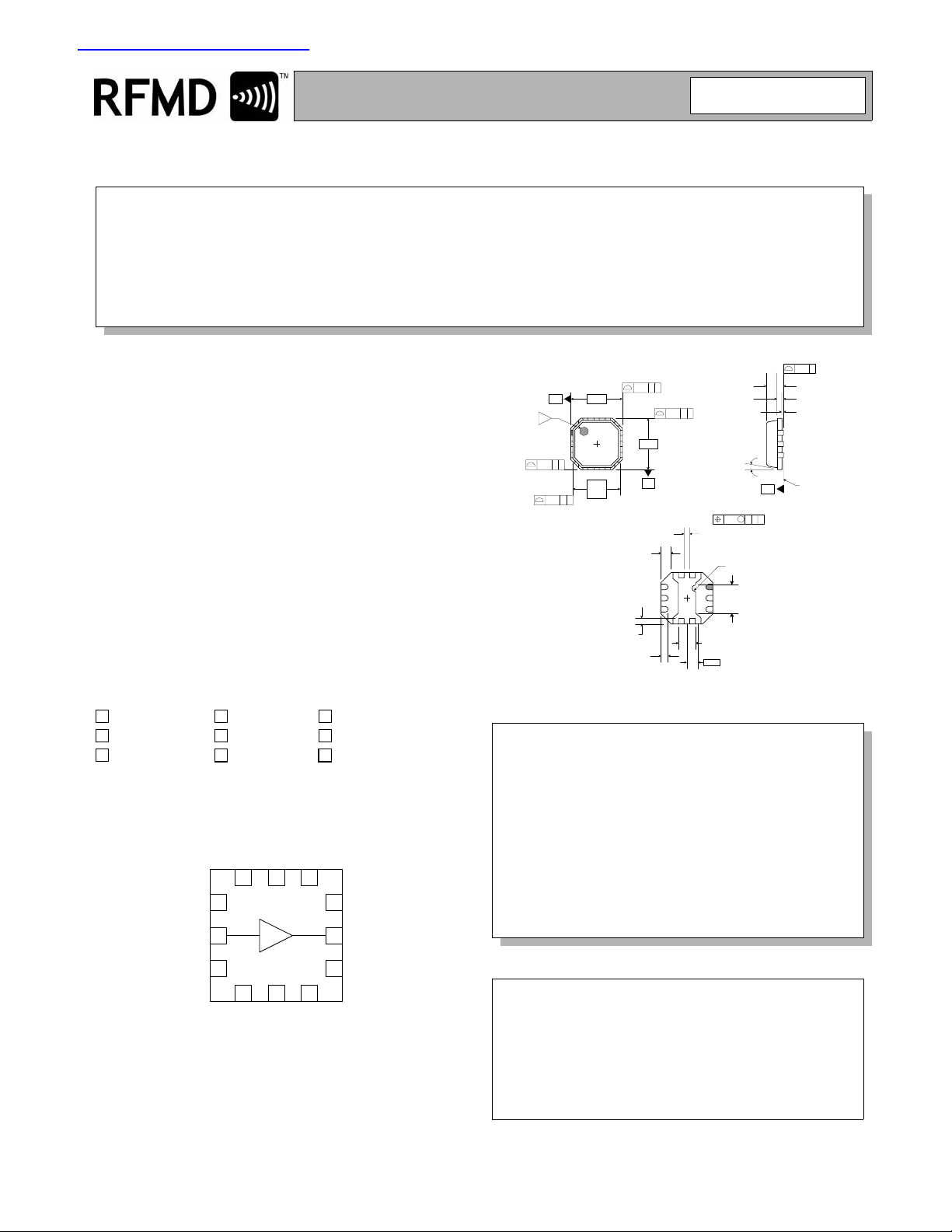
The RF3397 is a general purpose, low-cost RF amplifier
IC. The device is manufactured on an advanced Gallium
Arsenide Heterojunction Bipolar Transistor (HBT) process, and has been designed for use as an e asily-cascadable 50 Ω gain block. Applications include IF and RF
amplification in wireless voice and data communication
products operating in frequency b ands up to 6000MHz.
The device is self-contained with 50 Ω input and output
impedances and requires only two external DC-biasing
elements to operate as specified. The device is designed
for cost effective high reliability in a plastic package. The
3 mmx3mm footprint is compatible with standard ceramic
and plastic Micro-X packages.
GENERAL PURPOSE AMPLIFIER
• Driver Stage for Power Amplifiers
• Final PA for Low-Power Applications
• High Reliability Applications
2 PLCS
2 PLCS
2 PLCS
-A-
3
0.10 C B
0.10 C A
3.00
1
2.75
SQ
Shaded lead is pin 1.
0.45
0.35
0.10 C A
0.60
0.24
TYP
0.375
0.275
3.00
-B-
2 PLCS
0.10 C B
Dimensions in mm.
0.35
0.30
1.15
0.85
0.65
0.20
REF.
0.10 C ABM
PIN 1 ID
R0.20
1.90
1.60
12°
MAX
-C-
0.05 C
0.90
0.85
0.05
0.00
SEATING
PLANE
Optimum Technology Matching® Applied
Si BJT GaAs MESFETGaAs HBT
Si Bi-CMOS
InGaP/HBT
9
SiGe HBT
GaN HEMT SiGe Bi-CMOS
GND
GND
GND
GND
GND
NC
NC
12 11 10
1
2
3
4 5 6
GND
Si CMOS
9
NC
RF OUTRF IN
8
7
NC
Functional Block Diagram
Package Style: QFN, 12-Pin, 3x3
Features
• DC to >6000MHz Operation
• Internally Matched Input and Output
• 15.5dB Small Signal Gain
• +25.5dBm Output IP3
• +12.5dBm Output P1dB
• Footprint Compatible with Micro-X
Ordering Information
RF3397 General Purpose Amplifier
RF3397PCBA-41X Fully Assembled Evaluation Board
RF Micro Devices, Inc.
7628 Thorndike Road
Greensboro, NC 27409, USA
Tel (336) 664 1233
Fax (336) 664 0454
http://www.rfmd.com
Rev A6 061016
4-607
Page 2
RF3397
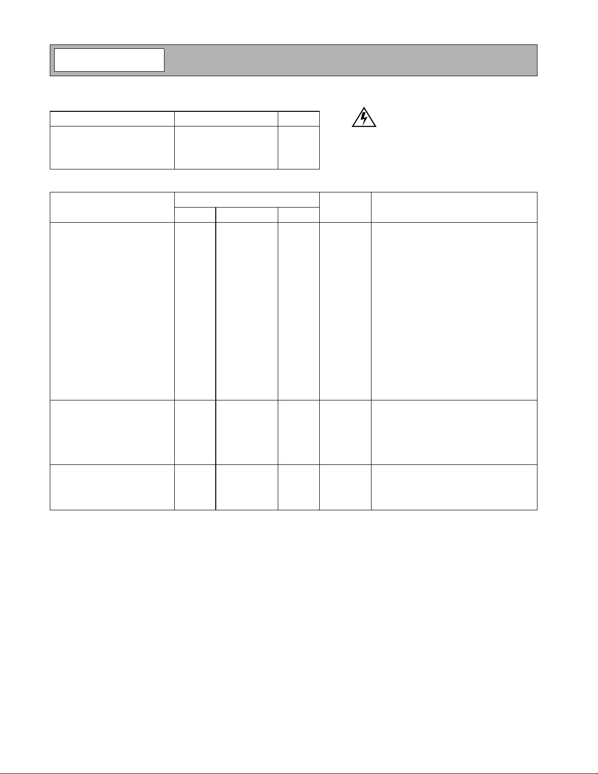
Absolute Maximum Ratings
Parameter Rating Unit
Input RF Power +13 dBm
Operating Ambient Temperature -40 to +85 ° C
Storage Temperature -60 to +150 °C
I
CC
60 mA
Caution! ESD sensitive device.
RF Micro Devices believes the furnished information is correct and accurate
at the time of this printing. RoHS marking ba sed on EUDirective2002/95/EC
(at time of this printing). However, RF Micro Devices reserves the right to
make changes to its products witho ut notice. RF Micro Devices does not
assume responsibility for the use of the described product(s).
Parameter
Min. Typ. Max.
Overall
Frequency Range DC to >6000 MHz
3dB Bandwidth 4.4 GHz
Gain 15.4 16.4 dB Freq=500MHz
Noise Figure 2.8 dB Freq=2000MHz
Input VSWR 1.7:1 In a 50Ω system, DC to 6000MHz
Output VSWR 2:1 In a 50Ω system, DC to 6000MHz
Output IP3 24.5 25.5 dBm Freq=850MHz
+24.5 +25.5 dBm Freq=2000MHz
Output P1dB +12.0 +13.0 dBm Freq=850MHz
+11.5 +12.5 dBm Freq=2000MHz
Reverse Isolation 19 dB Freq=2000MHz
Thermal
Theta
JC
Maximum Measured Junction
Temperature at DC Bias Conditions
Mean Time To Failures 51,709 years T
Power Supply
Device Operating Voltage 3.55 3.65 3.7 V At pin 8 with I
Operating Current 40 60 mA See Note 2.
Note 1: All specification and characterization data has been gathered on standard FR-4 evaluation boards. These evaluation boards are
not optimized for frequencies above 2.5GHz. Performance above 2.5GHz may improve if a high performance PCB is used.
Note 2: The RF3397 must be operated at or below 60mA in order to achieve the thermal performance stated above. Operating at 40mA
will ensure the best possible combination of reliability and electrical performance.
Note 3: Because of process variations from part to part, the current resulting from a fixed bias voltage will vary. As a result, caution
should be used in designing fixed voltage bias circuits to ensure the worst case bias current does not exceed 60mA over all intended
operating conditions.
Specification
15.3 16.3 17.3 dB Freq=850MHz
13.5 15.5 17.5 dB Freq=2000MHz
14.5 dB Freq=3000MHz
14.0 Freq=4000MHz
13.5 Freq=6000MHz
208 °C/W V
113 °C T
4.2 4.5 4.8 V At evaluation board connectors, I
Unit Condition
T=25°C, ICC=40mA (See Note 1.)
ICC=40mA, P
=3.38V
PIN
=+85°C
AMB
=+85°C
AMB
With 22Ω bias resistor
=135mW. (See Note 3.)
DISS
=40mA
CC
=40mA
CC
4-608
Rev A6 061016
Page 3
RF3397
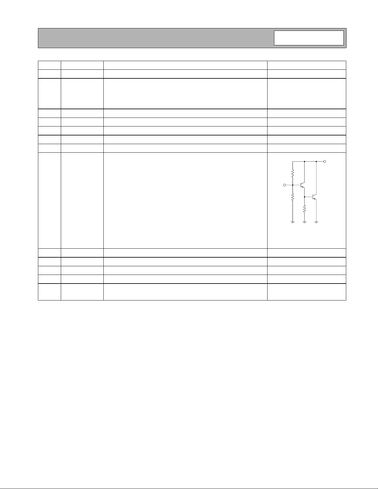
Pin Function Description Interface Schematic
1NC
2RF IN
3NC
4GND
5GND
6GND
7NC
8RF OUT
9NC
10 GND
11 GND
12 GND
Die
GND
Flag
No internal connections. It is not necessary to ground this pin.
RF input pin. This pin is NOT internally DC blocked. A DC blocking
capacitor, suitable for the frequency of operation, should be used in
most applications. DC coupling of the input is not allowed, because this
will override the internal feedback loop and cause temperature instability.
No internal connections. It is not necessary to ground this pin.
Ground connection.
Ground connection.
Ground connection.
No internal connections. It is not necessary to ground this pin.
RF output and bias pin. Biasing is accomplished with an external series
resistor and choke inductor to V
DC current into this pin to a desired level. The resistor value is deter-
mined by the following equation:
-------------------------------------------------------
R
=
Care should also be taken in the resistor selection to ensure that the
current into the part never exceeds 60mA over the planned operating temperature. This means that a resistor between the supply and
this pin is always required, even if a supply near 3.6V is available, to
provide DC feedback to prevent thermal runaway. Because DC is
present on this pin, a DC blocking capacitor, suitable for the frequency
of operation, should be used in most applications. The supply side of
the bias network should also be well bypassed.
No internal connections. It is not necessary to ground this pin.
Ground connection.
Ground connection.
Ground connection.
Ground connection. To ensure best performance, avoid placing ground
vias directly beneath the part.
. The resistor is selected to set the
CC
V
SUPPLYVDEVICE
–()
I
CC
RF IN
RF OUT
Rev A6 061016
4-609
Page 4
RF3397
J1
RF IN
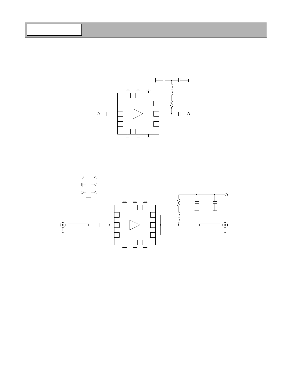
Application Schematic
V
CC
10 nF 22 pF
47 nH
12 11 10
RF IN
1
22 pF
2
3
4 5 6
9
8
7
R
BIAS
22 pF
RF OUT
Evaluation Board Schematic
(Download Bill of Materials from www.rfmd.com.)
P1
P1-1 VCC
P1-3 NC
50 Ω μstrip 50 Ω μstrip
1
2
3
CON3
GND
C1
100 pF
12 11 10
1
2
3
4 5 6
R1
22 Ω
9
8
7
L1
100 nH
C3
100 pF
C2
100 pF
C4
1 μF
VCC
P1-1
J2
RF OUT
4-610
NOTE:
Evaluation board optimized for frequencies above 300 MHz and below 2.5 GHz.
For operation below 300 MHz the value of inductor L1 and capcitors C1 and C2
should be increased.
Rev A6 061016
Page 5
RF3397
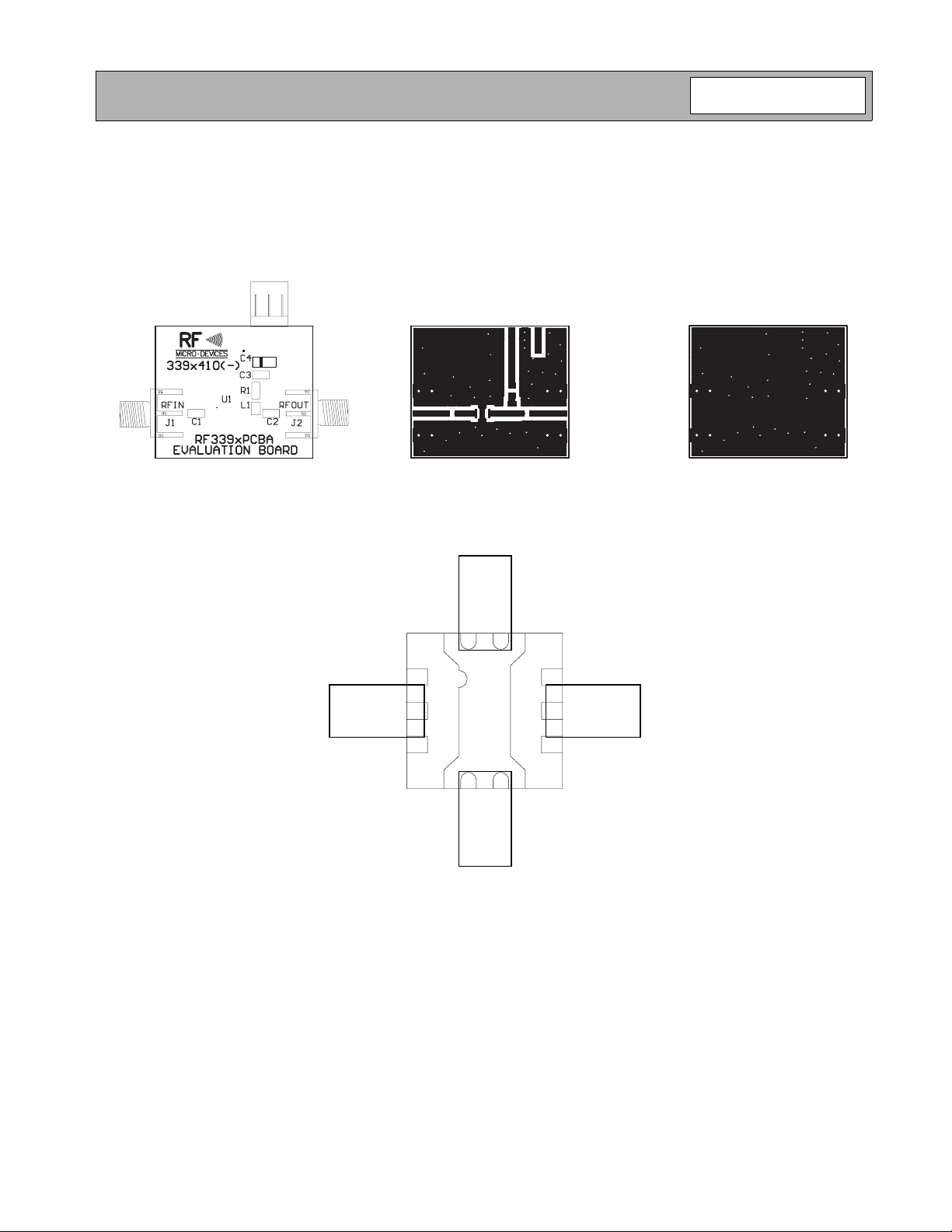
Evaluation Board Layout
Board Size 1.195" x 1.000"
Board Thickness 0.033”, Board Material FR-4
Note: A small amount of ground inductance is required to achieve datasheet performance. The necessary inductance
may be generated by ensuring that no ground vias are placed directly below the footprint of the part.
Overlay of Suggested Micro-X and 3mmx3mm Layouts Showing
Compatibility
Rev A6 061016
4-611
Page 6
RF3397
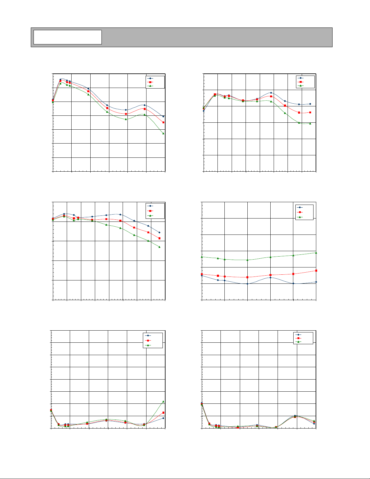
Gain versus Frequency Across Temperature
17.0
16.0
15.0
14.0
13.0
Gain (dB)
12.0
11.0
10.0
100.0 1100.0 2100.0 3100.0 4100.0 5100.0 6100.0
ICC=40mA
Frequency (MH z)
Output IP3 versus Frequency Across Temperature
30.0
25.0
20.0
OIP3 (dBm)
15.0
ICC=40mA
-40°C
+25°C
+85°C
-40°C
+25°C
+85°C
Output P1dB versus Frequency Across Temperature
16.0
14.0
12.0
10.0
Output P1dB (dBm)
8.0
6.0
4.0
100.0 600.0 1100.0 1600.0 2100.0 2600.0 3100.0 3600.0 4100.0
ICC=40mA
Frequency (M Hz)
Noise Figure versus Frequency Over Temperature
5.0
4.5
4.0
3.5
Noise Figure (dB)
3.0
ICC=40mA
-40°C
+25°C
+85°C
-40°C
+25°C
+85°C
10.0
5.0
100.0 600.0 1100.0 1600.0 2100.0 2600.0 3100.0 3600.0 4100.0
Frequency (MH z)
Input VSWR versus Frequency Across Temperature
5.0
4.5
4.0
3.5
3.0
VSWR
2.5
2.0
1.5
1.0
100.0 1100.0 2100.0 3100.0 4100.0 5100.0 6100.0
ICC=40mA
Frequency (M Hz)
4-612
-40°C
+25°C
+85°C
2.5
2.0
500.0 1000.0 1500.0 2000.0 2500.0 3000.0
Frequency (MH z)
Output VSWR versus Frequency Across Temperature
5.0
4.5
4.0
3.5
3.0
VSWR
2.5
2.0
1.5
1.0
100.0 1100.0 2100.0 3100.0 4100.0 5100.0 6100.0
ICC=40mA
Frequency (MH z)
-40°C
+25°C
+85°C
Rev A6 061016
Page 7
RF3397
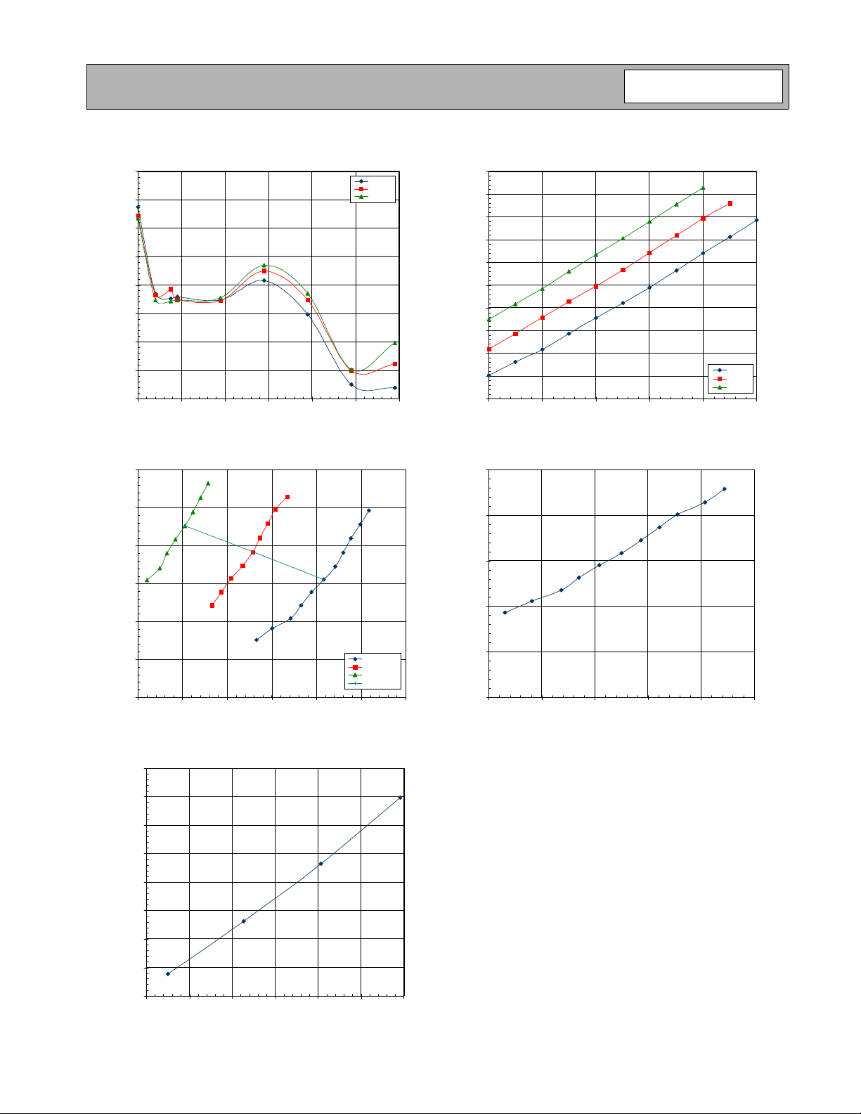
Reverse Isolation versus Fr equency Across
21.5
21.0
20.5
20.0
19.5
19.0
Temperat ure, I
=40mA
CC
Reverse Isolation (dB)
18.5
18.0
17.5
100.0 1100.0 2100.0 3100.0 4100.0 5100.0 6100.0
Frequency (M Hz)
Current versus Voltage
60.0
50.0
40.0
30.0
(mA)
CC
I
20.0
(At Pin 8 of the RF3397 )
-40°C
+25°C
+85°C
Current ve rsus Voltage
60.0
55.0
50.0
45.0
40.0
35.0
(mA)
CC
I
30.0
25.0
20.0
15.0
10.0
(At Evaluation Board Connector, R
4.04.24.44.64.85.0
VCC (V)
BIAS
=22Ω)
-40°C
+25°C
+85°C
Power Dissipated versus Voltage at Pin 8
T
=85°C
0.25
0.20
0.15
0.10
Power Dissipated (W)
AMB
10.0
0.0
3.4 3.5 3.6 3.7 3.8 3.9 4.0
Junction Temperature versus Power Dissipated
140.00
135.00
130.00
125.00
(°C)
120.00
MAX
T
115.00
110.00
105.00
100.00
0.09 0.11 0.13 0.15 0.17 0.19 0.21
Rev A6 061016
T
AMB
V
PIN
=+85°C
P
DISS
(V)
(W)
-40°C
+25°C
+85°C
Vcc= 4.5V
0.05
0.00
3.38 3.43 3.48 3.53 3.58 3.63
V
(V)
PIN
4-613
Page 8
RF3397
PCB Design Requirements
PCB Surface Finish
The PCB surface finish used for RFMD’s q ua lific ation process is Electroless Nicke l , immer sio n G old . Typical thickness is
3μinch to 8μinch Gold over 180μinch Nickel.
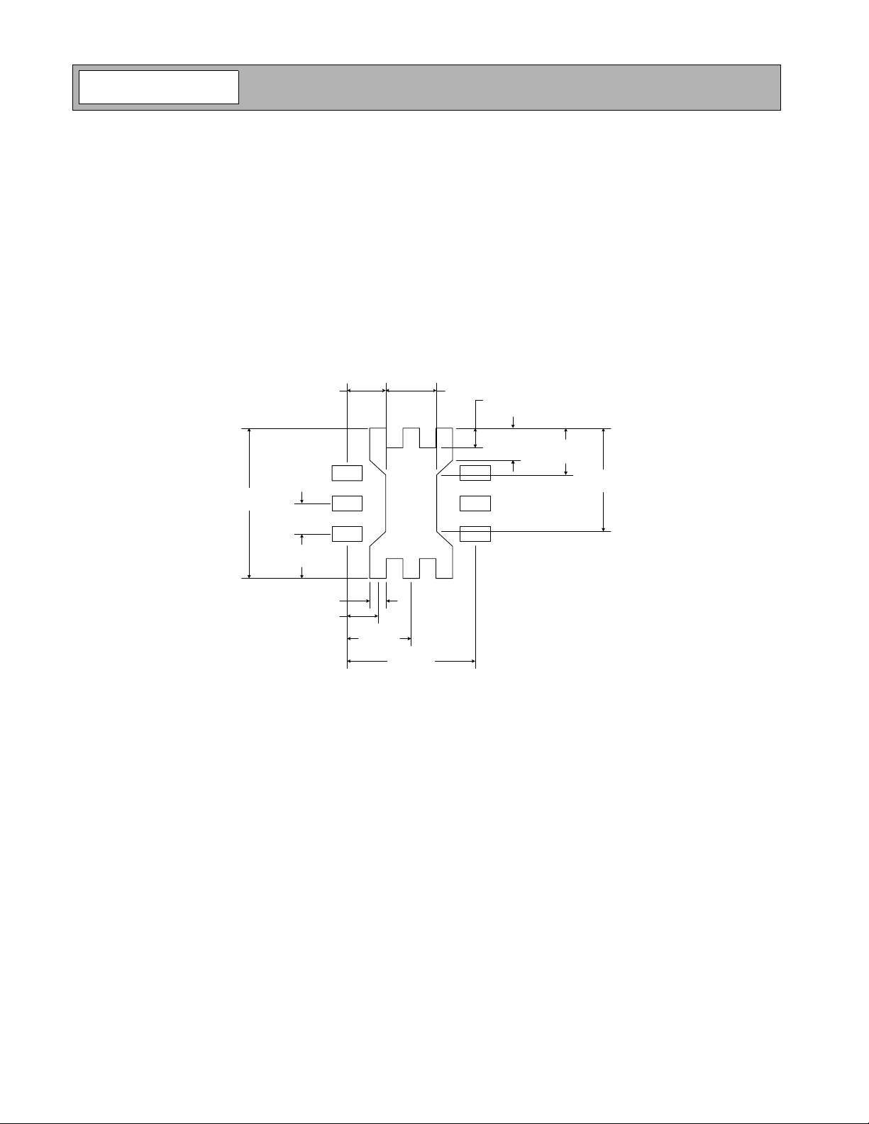
PCB Land Pattern Recommendation
PCB land patterns are based on IPC-SM-782 standards when possible. The pad pattern shown has been developed and
tested for optimized assembly at RFMD; however, it may require some modifications to address company specific
assembly processes. The PCB land pattern has been developed to accommodate lead and package tolerances.
PCB Metal Land Mask Pattern
A = 0.59 x 0.32 (mm) Typ.
0.80 (mm) Typ. 1.00 (mm)
Pin 1
3.20 (mm)
Typ.
0.65 (mm)
Typ.
0.95 (mm)
Typ.
0.30 (mm) Typ.
0.65 (mm) Typ.
Figure 1. PCB Metal Land Pattern (Top View)
A
A
A
1.30 (mm)
Typ.
2.60 (mm)
0.40 (mm) Typ.
0.70 (mm)
Typ.
A
A
A
1.00 (mm)
Typ.
2.20 (mm)
Typ.
4-614
Rev A6 061016
Page 9
RF3397
PCB Solder Mask Pattern
Liquid Photo-Imageable (LPI) solder mask is recommended. The solder mask footprint will match what is shown for the
PCB metal land pattern with a 2 mil to 3 mil expansion to accommodate solder mask registration clearance a round all
pads. The center-grounding pad shall also have a solder mask clearance. Expansion of the pads to create s older mask
clearance can be provided in the master data or requested from the PCB fabrication supplier.
A = 0.72 x 0.45 (mm) Typ.
0.72 (mm) Typ. 1.15 (mm)
0.41 (mm) Typ.
3.32 (mm)
Typ.
Pin 1
0.65 (mm)
Typ.
1.01 (mm)
Typ.
0.45 (mm) Typ.
0.65 (mm) Typ.
A
A
A
1.30 (mm)
Typ.
0.75 (mm)
A
A
A
2.60 (mm)
Typ.
1.05 (mm)
Typ.
2.27 (mm)
Typ.
Figure 2. PCB Solder Mask (Top View)
Thermal Pad and Via Design
The PCB metal land pattern has been designed with a thermal pad that matches the exposed die paddle size on the bottom of the device.
Thermal vias are required in the PCB layout to effectively conduct heat away from the pac kage. The via pattern has been
designed to address thermal, power dissipation and electrical requirements of the device as well as accommodating
routing strategies.
The via pattern used for the RFMD qualification is based on thru-hole vias with 0.203mm to 0.330mm finished hole size
on a 0.5 mm to 1.2mm grid patter n with 0.025mm plating on via walls. If micro vias are used in a design, it is suggested
that the quantity of vias be increased by a 4:1 ratio to achieve similar results.
NOTE: A small amount of ground inductance is required to achieve data sheet performance. The necessary in ductance
may be generated by ensuring that no ground vias are placed directly below the footprint of the part.
Rev A6 061016
4-615
Page 10

RF3397
4-616
Rev A6 061016
 Loading...