

Page 1

Data Sheet Conexant Systems, Inc. Doc. No. 101251A
August 24, 2000
RF250
Rx ASIC for CDMA, AMPS, and PCS Applications
The RF250 Application-Specific Integrated Circuit (ASIC) is a
triple-mode, dual-band receiver (Rx) intended for use in Code
Division Multiple Access (CDMA) portable phones in both
cellular and Personal Communications System (PCS) bands. As
a dual mode IC, it can be used in CDMA mode or Advanced
Mobile Phone System (AMPS) mode.
The device incorporates all the components required to
implement the receiver front end and the In-Phase and
Quadrature (I/Q) demodulator stages except for the filter blocks
and PCS Low Noise Amplifier (LNA). Besides a cellular band
LNA, there are separate mixers for AMPS, CDMA 800 MHz, and
PCS bands. The AMPS mixer output is single-ended, followed
by the AMPS Intermediate Frequency (IF) Surface Acoustic
Wave (SAW) filter. The cellular and PCS mixers have balanced
outputs for the CDMA IF SAW filters. The mixers are followed by
an IF Variable Gain Amplifier (VGA) and an I/Q demodulator.
The outputs from the filters are combined through separate
buffers at the input of the VGA. The buffers are enabled
depending on the selected mode. The VGA has a gain control
range greater than 90 dB. There are two VHF oscillators that
operate with external tank circuits. They provide signals to the
Local Oscillator (LO) for the I/Q demodulator in the cellular and
PCS bands.
The noise figure, gain, and third order Input Intercept
Point (IIP3) of each stage in the receiver chip are
optimized to meet the system requirements for AMPS
and CDMA modes as per TIA/EIA-98-B and ANSI JSTD-018 (PCS). Employing silicon bipolar technology,
the ASIC is designed for high performance and a high
level of integration.
The device package and pinout are shown in Figure 1. A
block diagram of the RF250 is shown in Figure 2.
Features
• Supports CDMA/AMPS/PCS1900
modes.
• Three battery cell operation
(2.7 V < VCC < 3.6 V).
• Higher level of integration.
• I/Q outputs.
• On-chip 100 to 640 MHz oscillators.
• Low power operation: <60 mA.
• 48-pin Thin Quad Flat Pack (TQFP)
package with downset paddle.
Applications
• Tri-mode handsets.
• CDMA and AMPS modes in the
cellular band:
-AMPS
- CDMA-US
- CDMA-J
• CDMA mode in the PCS band:
- US-PCS
-K-PCS
1
48 47 46 45 44 43 42 41 40 39 38 37
13 14 15 16 17 18 19 20 21 22 23 24
2
3
4
5
6
7
8
9
10
11
12
36
35
34
33
32
31
30
29
28
27
26
25
C452
GND
CELL_LNA_DECOUPLE
NC
CELL_LNA_IN
VCC1
CELL_BIAS_SET
CELL/PCS
FM/CDMA
VCC2
GND
CELL_TANK-
CELL_TANK+
PCS_TANK-
PCS_TANK+
DIV2/DIV4
PLL+
PLL-
GND
I-
I+
Q+
Q-
SLEEP
VGA_CONTROL
CELL_LNA_OUT
GND
PCS_BIAS_SETNCCELL_MIX_GND
CELL_IFTRAP
CELL_MIX_IN
VCC4
PCS_MIX_IN
CELL_LO
PCS_LO
PCS_MIX_BYPASS
PCS_IF_OUT+
PCS_IF_OUTAMPS_IF_OUT
CDMA_IF_OUT+
CDMA_IF_OUTCELL_MIX_BYPASS
VGA_PCS_IN+
VGA_PCS_INVGA_AMPS_IN
VGA_CDMA_IN+
VGA_CDMA_INVCC3
Figure 1.RF250Rx ASIC Pinout – 48-Pin TQFP
Package With Downset Paddle
Page 2
Rx ASIC RF250
2 Conexant Systems, Inc. 101251A
August 24, 2000
Technical Description
Low Noise Amplifier (LNA). The cellular band
LNA is designed with a low noise figure and high
linearity to achieve maximum receiver dynamic
range. Pin 2, the 800 LNA decouple pin, is
required to be grounded through an RF bypass
capacitor with minimum trace length. The input
and output match are external to the chip.
Mixers. The RF250 Rx ASIC has three
independent mixers, one for the PCS band and
two for the cellular band (AMPS and CDMA).
The mixers are designed to operate with very low
LO powers of –10 dBm. The LO ports are matched
internal to the chip.
The cellular band mixers have a high gain and a
low noise figure that allow them to meet the
system noise figure. The cellular CDMA and PCS
mixers have balanced output to drive the IF filters.
The AMPS mixer has a single-ended output to
match the standard IF SAW filters.
Variable Gain Amplifier (VGA). The high dynamic
range required by CDMA handsets is achieved by
the VGA, which is common to all modes. The VGA
has a minimum dynamic range of 90 dB with a
control voltage of 0.2 to 2.7 volts. The appropriate
signal path is switched internal to the device. This
eliminates off-chip switching needed to operate
this common VGA in cellular AMPS, CDMA, and
PCS modes.
I/Q Demodulator. The local oscillator signals are
generated on-chip. The I/Q demodulator is
internally connected to the VGA output. It is
designed to have a very low amplitude and phase
imbalance. The I and Q outputs are differential.
The DC offsets between the differential outputs
and between I and Q channels are designed to be
extremely low to facilitate compatibility with
baseband Interfaces.
VHF Oscillators. There are two on-chip
oscillators, one for the cellular and one for the PCS
bands. These Voltage Controlled Oscillators
(VCOs) work with external tank circuits and
varactor diodes. The outputs of the differential
oscillators are buffered and the output is used to
drive the prescaler of an external Phase Locked
Loop (PLL). The VCOs typically operate at twice
the IF frequency and can operate at up to four
times the IF frequency.
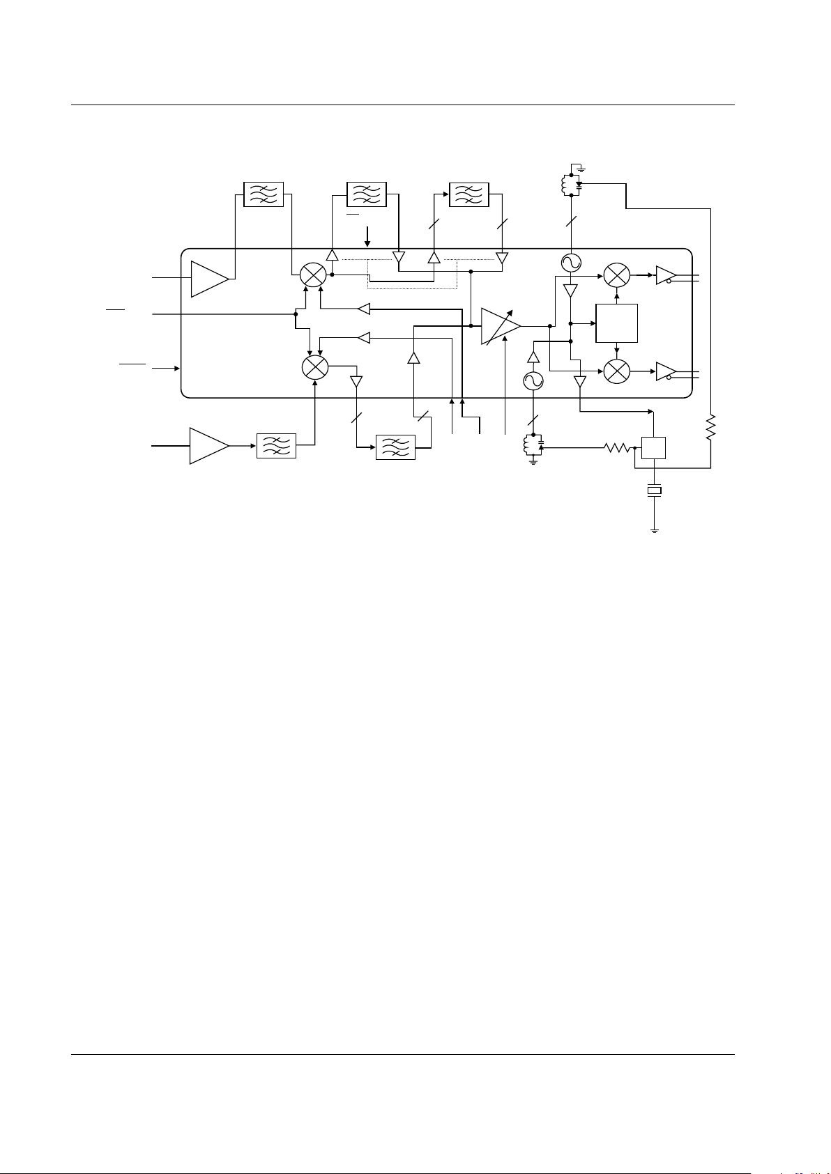
Figure 2. RF250 Rx ASIC Block Diagram
÷ 2,4
AMPS IF SAW
CDMA IF SAW
I
Q
RF250
Rx ASIC
RF SAW(CELL)
RF SAW (PCS)
IF SAW (PCS)
PLL
CELL_LNA_IN
PCS_LNA_IN
4
7
48
42
34
28
32, 33
26, 27
11,12
19
20
21
22
C262
16,17
13,14
40
35,36
29,30
PCS_LO
CELL_LO
VGA_CONTROL
22
2
2
2
2
38
39 24
CELL/PCS
FM/CDMA
8
SLEEP
23
Page 3
RF250 Rx ASIC
101251A Conexant Systems, Inc. 3
August 24, 2000
The local oscillators for the I/Q demodulators are
derived by an on-chip frequency divider. The logic
signal to select the divider ratio (2 or 4) is available
onPin15(DIV2/DIV4).
Mode Control. The operation of the chip is
controlled by signals at Pin 7 (CELL/PCS), Pin 8
(FM/CDMA), Pin 23 (SLEEP), and the DIV2/DIV4
select commands at Pin 15. All the switching is
done internally. The supply voltage should be
present at all the VCC pins for normal operation.
The internal switching needed to select each of
these signals is shown in Table 1.
Electrical and Mechanical Specifications.
Included in this document are Tables 1 through 5
and Figures 1 through 29, which define the
electrical and mechanical specifications of the
RF250.
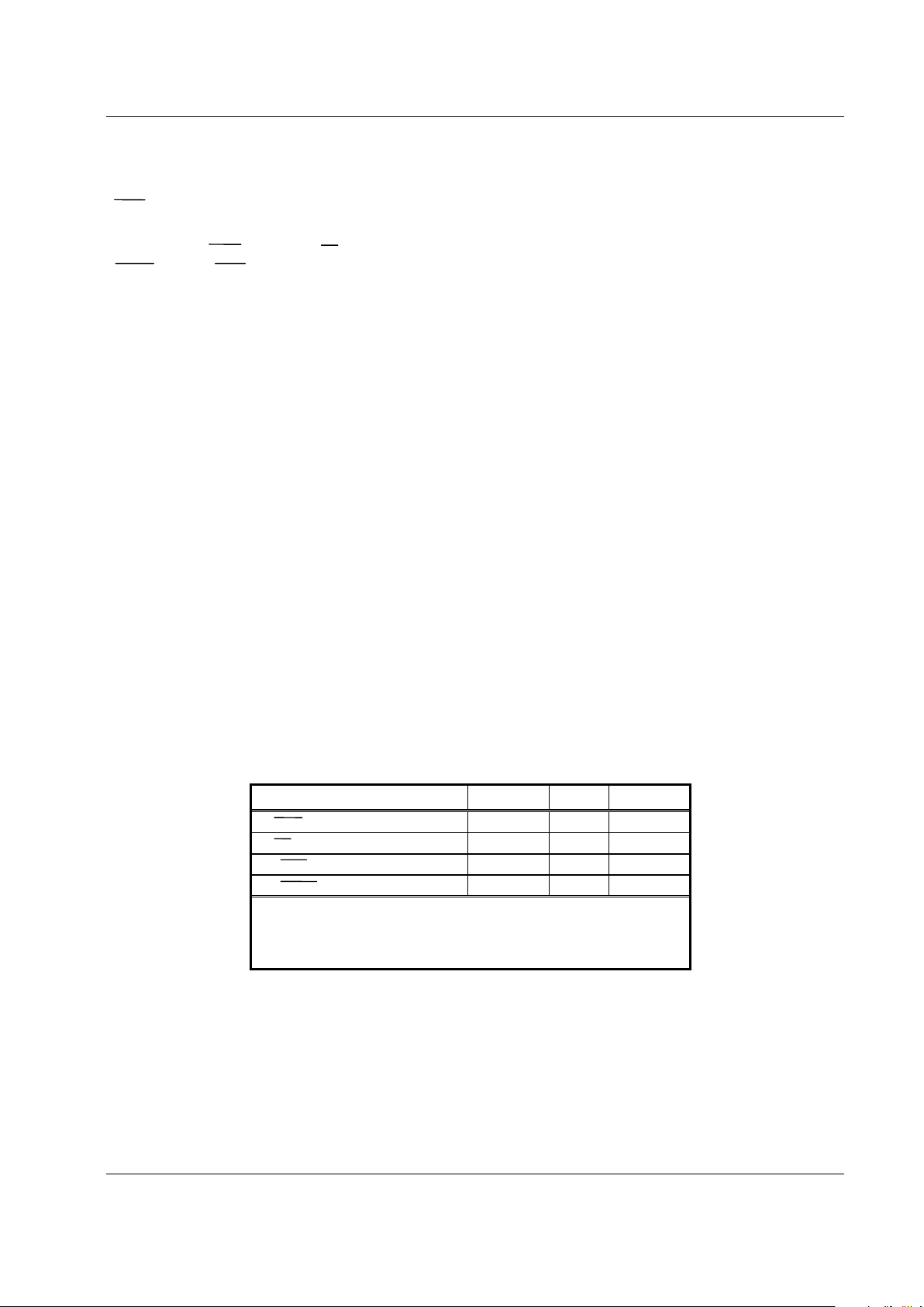
Table 1: Mode Control Select Signal
Switching
Table 2: Pin Assignments and Functional
Pin Descriptions
Table 3: Absolute Maximum Ratings
Table 4: Recommended Operating
Conditions
Table 5: Electrical Specifications
Figure 1: Pinout Configuration
Figure 2: Functional Block Diagram
Figures 3 - 27: Typical Functional Block
Performances
Figure 28: Package Dimensions
Figure 29: Tape and Reel
Dimensions
ESD Sensitivity
The RF250 is a Class 1 device. The following
extreme Electrostatic Discharge (ESD) precautions
are required according to the Human Body Model
(HBM):
• Protective outer garments.
• Handle device in ESD safeguarded work
area.
• Transport device in ESD shielded
containers.
• Monitor and test all ESD protection
equipment.
The HBM ESD withstand threshold value, with
respect to ground, is ±1.5kV.TheHBMESD
withstand threshold value, with respect to VDD
(the positive power supply terminal) is also ±1.5
kV.
Table 1. Mode Control Select Signal Switching
Pin AMPS CDMA PCS
7 (CELL/PCS) 0
0
1
8 (FM/CDMA) 0 1 x
15 (DIV2/DIV4) 0 0 0
23 (SLEEP) 1 1 1
Key: 0 = LOW
1=HIGH
x=N/A
Page 4
Rx ASIC RF250
4 Conexant Systems, Inc. 101251A
August 24, 2000
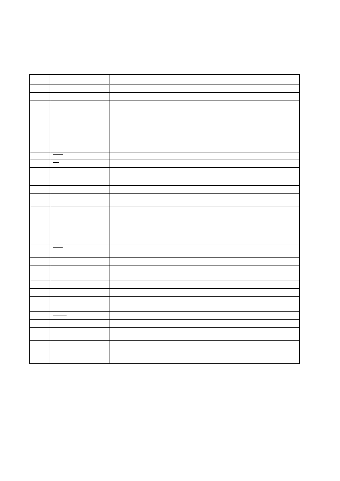
Table 2. RF250 Signal Description (1 of 2)
Pin # Name Description
1
G
ND Ground
2 CELL_LNA_DECOUPLE An RF bypass capacitor with very short trace should be connected to this pin.
3 NC No connection
4 CELL_LNA_IN The input to LNA needs external matching. The matching network should be placed as close
to this pin as possible. High Q components are recommended to minimize the effect on the
noise figure.
5 VCC1 Supply voltage to the RF bias. An RF bypass capacitor should be connected from the pin to
ground with short traces..
6 CELL_BIAS_SET
This pin sets the cellular RF bias current. Typically, a 180 Ω resistor is connected from the
pin to ground.
7 CELL/PCS Band select: 0 = cellular (800 MHz); 1 = PCS (1900 MHz).
8 FM/CDMA Cellular band mode select: 0 = AMPS; 1 = CDMA.
9 VCC2 Voltage supply pin to the VCO buffer. A bypass capacitor should be placed close to the
device from pin 9 to pin 10. The trace should be short and connected immediately to the
ground plane for best performance.
10 GND Ground return from the VCO buffer.
11 CELL_TANK– Differential tank connection for the cellular band VCO. Care should be taken during the
layout of the externaltank circuit to prevent parasitic oscillations.
12 CELL_TANK+ Differential tank connection for the cellular band VCO. Care should be taken during the
layout of the externaltank circuit to prevent parasitic oscillations.
13 PCS_TANK– Differential tank connection for the PCS band VCO. Care should be taken during the layout
of the external tank circuit to prevent parasitic oscillations.
14 PCS_TANK+ Differential tank connection for the PCS band VCO. Care should be taken during the layout
of the external tank circuit to prevent parasitic oscillations.
15 DIV2/DIV4 Selects the divide ratio of the VCO to the LO port of the I/Q demodulator: 0 = divide by 2,
1 = divide by 4.
16 PLL+ Differential buffered VCO output.
17 PLL– Differential buffered VCO output.
18 GND Ground
19 I– I channel differential output.
20 I+ I channel differential output.
21 Q+ Q channel differential output.
22 Q– Q channel differential output.
23 SLEEP Activates sleep mode: 0 = sleep; 1 = enable
24 VGA_CONTROL
VGA voltage input. Input impedance is greater than 50K Ω.
25 VCC3 Voltage supply to VGA and I/Q demodulator stages. Supply should be well regulated and
bypassed to prevent modulation of the signal by the supply ripple.
26 VGA_CDMA_IN– CDMA differential VGA input
27 VGA_CDMA_IN+ CDMA differential VGA input
28 VGA_AMPS_IN AMPS VGA input.
Page 5
RF250 Rx ASIC
101251A Conexant Systems, Inc. 5
August 24, 2000
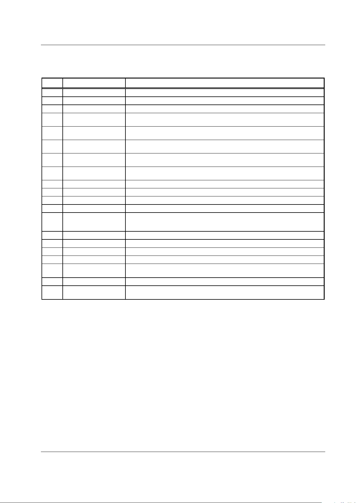
Table 2. RF250 Signal Description (2 of 2)
Pin # Name Description
29 VGA_PCS_IN–
P
CS differential VGA input.
30 VGA_PCS_IN+ PCS differential VGA input.
31 CELL_MIX_BYPASS Low frequency bypass for the AMPS mixer.
32 CDMA_IF_OUT– CDMA differential mixer output. Requires an external inductor to VCC. Output impedance is
set by an external match.
33 CDMA_IF_OUT+ CDMA differential mixer output. Requires an external inductor to VCC. Output impedance is
set by an external match.
34 AMPS_IF_OUT AMPS mixer output. Requires an external inductor to VCC. Output impedance is set by an
external match.
35 PCS_IF_OUT– PCS differential mixer output. Requires an external inductor to VCC. Output impedance is
set by an external match.
36 PCS_IF_OUT+ PCS differential mixer output. Requires an external inductor to VCC. Output impedance is
set by an external match.
37 PCS_MIX_BYPASS Low frequency bypass for the PCS mixer.
38 PCS_LO The local oscillator input for the PCS band.
39 CELL_LO The local oscillator input for the cellular band.
40 PCS_MIX_IN PCS mixer input.
41 VCC4 Voltage supply pin for the mixers. An RF bypass capacitor should be connected from this pin
to ground. It should be connected as close to the device as possible with very short trace
lengths.
42 CELL_MIX_IN Cellular mixer input.
43 CELL_IFTRAP Theparallel LC circuit is tuned to the cellular IF frequency.
44 CELL_MIX_GND Add inductance from the pin to ground to lower mixer gain and increase IIP3.
45 NC No connection
46 PCS_BIAS_SET
This pin sets the PCS RF bias current. Typically, a 180 Ω resistor is connected from the pin
to ground.
47 GND Ground
48 CELL_LNA_OUT Cellular band LNA output. This is an open collector output. An inductor must be connected to
VCC. The matching is done externally to the chip.
Page 6
Rx ASIC RF250
6 Conexant Systems, Inc. 101251A
August 24, 2000
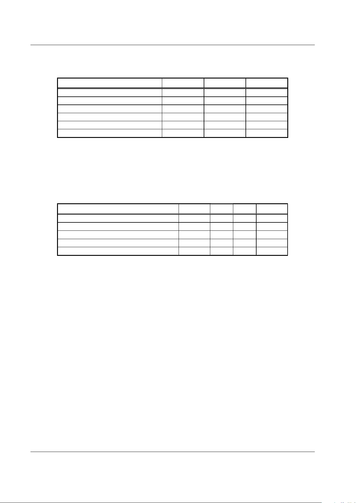
Table 3. Absolute Maximum Ratings
Parameter Minimum Maximum Units
Supply voltage (VCC) –0.3 +5.5
V
Input voltage range –0.3 VCC V
LNA input power -- +5 dBm
Power dissipation -- 600 mW
Ambient operating temperature –30 +80 °C
Storage temperature –40 +125 °C
Parameter Min Typical Max Units
Supply voltage (VCC)
2.73.33
.6 V
Operating temperature –30 +25 +80 °C
Impedance of logic inputs 50
KΩ
Logic 0 0.0 0.5 V
Logic 1 VCC – 0.5 VCC V
Table 4. Recommended Operating Conditions
Page 7

RF250 Rx ASIC
101251A Conexant Systems, Inc. 7
August 24, 2000
Table 5. RF250 Rx ASIC Electrical Specifications (1 of 3)
TA = 25°°°° C, VCC = 3.3 V, PLO = –10 dBm
Parameter Symbol Test Condition Min Typical Max Units
Cellular LNA
Gain @ 881 MHz 13 dB
Gain variation over band (869-894 MHz) 0.5 dB
Gain variation over temperature 1.5 dB
Noise figure @ 881 MHz 2.0 dB
Reverse isolation 20 dB
P1dB @ input –5 dBm
IP3 @ input 8dBm
Input return loss (869-894 MHz) –12 dB
Output return loss (869-894 MHz) –15 dB
Total supply current (adjustable) 12 mA
Cellular Mixer
Conversion gain (power):
CDMA mode
AMPS mode
14
11
dB
dB
Single-sideband noise figure:
CDMA mode
AMPS mode
7.5
8
dB
dB
P1dB @ input:
CDMA mode
AMPS mode
–6
–9
dBm
dBm
IP3 @ input:
CDMA mode
AMPS mode
5
3
dBm
dBm
Mixer RF input return loss, RF port 1 (869-894
MHz)
–15 dB
LO input power level –10 dBm
IF output resistance:
CDMA mode (differential)
AMPS mode (single-ended)
3000
1000
Ω
Ω
IF frequency range 300 MHz
LO/RF input isolation 20 dB
Total supply current 18 mA
Page 8

Rx ASIC RF250
8 Conexant Systems, Inc. 101251A
August 24, 2000
Table 5. RF250 Rx ASIC Electrical Specifications (2 of 3)
TA = 25°°°° C, VCC = 3.3 V, PLO = –10 dBm
Parameter Symbol Test Condition Min Typical Max Units
PCS Mixer
Conversion gain (power) 10 dB
Single-sideband noise figure 12 dB
P1dB @ input –5 dBm
IP3 @ input 5dBm
RF input return loss (1930-1990 MHz) –15 dB
LO input power level –10 dBm
IF output resistance (differential) 1000
Ω
IF frequency range 300 MHz
LO/LNA input isolation 25 dB
LO/RF input isolation 20 dB
Total supply current (adjustable) 24 mA
Rx VGA - I/Q Demodulator
Frequency range 50 300 MHz
Input impedance:
CDMA input (differential)
PCS input (differential)
AMPS input (single-ended)
1000
1000
1000
Ω
Ω
Ω
Gain:
Maximum
Minimum
Maximum (AMPS)
Minimum (AMPS)
53
–47
61
–39
54
–42
62
–34
55
–37
63
–29
dB
dB
dB
dB
Gain slope 45 dB/V
Gain slope linearity (over any 6 dB segment) –3 +3 dB
IF amplifier IIP3:
@ Maximum gain (CDMA and PCS mode)
@ maximum gain (AMPS mode)
–50
–58 dBm
Input 1 dB compression @ minimum gain –10 dBm
IF amplifier noise figure:
@ Maximum gain
Minimum gain
5
50
dB
dB
Page 9

RF250 Rx ASIC
101251A Conexant Systems, Inc. 9
August 24, 2000
Parameter Symbol Test Condition Min Typical Max Units
Rx VGA - I/Q Demodulator (continued)
Output level:
CDMA
AMPS
2.75
5.5
mVrms
mVrms
Maximum output level 1.4 Vp-p
Gain variation over frequency:
CDMA (1-630 kHz)
AMPS (0.1-12.2 kHz)
0.1
0.1
0.3
0.3dBdB
Output impedance (differential) 500
I+, I–, and Q+, Q– DC offset 6mVrms
I/Q gain mismatch 0.2 0.3 dB
I/Q phase mismatch 2 4 deg
I to Q DC offset 30 mV
Total supply current (includes I/Q mixers, LO
buffers, and dividers)
15 mA
Oscillator
Frequency range 100 640 MHz
Phase noise (fc = 200 MHz, unloaded Q = 20) @
100 kHz offset
–117 dBc/Hz
Second harmonic distortion (application dependent) –30 –26 dBc
Output level to PLL (differential) 300 mVp-p
Output impedance to PLL (differential) 300
Ω
Reverse isolation –30 –40 dB
Total supply current 5mA
Table 5. RF250 Rx ASIC Electrical Specifications (3 of 3)
TA = 25°°°° C, VCC = 3.3 V, PLO = –10 dBm
Page 10

Rx ASIC RF250
10 Conexant Systems, Inc. 101251A
August 24, 2000
0
2
4
6
8
10
12
14
16
2.42.62.8 3 3.23.43.63.8
Vcc (V)
Gain (dB)
-30 de g C
25 deg C
80 deg C
Figure 3. LNA Gain Over Temperature at 881.52 MHz
0
0.5
1
1.5
2
2.5
3
2.4 2.6 2.8 3 3.2 3.4 3.6 3.8
Vcc (V)
Noise Figure(dB)
-30 deg C
25 deg C
80 deg C
Figure 4. LNA Noise Figure at 881.52 MHz
0
2
4
6
8
10
12
2.4 2.6 2.8 3 3.2 3.4 3.6 3.8
Vcc (V)
IIP3(dBm)
-30 deg C
25 deg C
80 deg C
Figure 5. LNA IIP3 at 881.52 MHz
0
2
4
6
8
10
12
14
2.4 2.6 2.8 3 3.2 3.4 3.6 3.8
Vcc (V)
Gain (dB)
-30 deg C
25 deg C
80 deg C
Figure 6. AMPS Mixer Gain
(RF Frequency = 881.52 MHz, LO Frequency = 966.90 MHz,
IF Frequency = 85.38 MHz)
0
1
2
3
4
5
6
7
8
9
10
2.4 2.6 2.8 3 3.2 3.4 3.6 3.8
Vcc (V)
NoiseFigure(dB)
-30 deg C
25 deg C
80 deg C
-10
-8
-6
-4
-2
0
2
4
6
8
10
2.4 2.6 2.8 3 3.2 3.4 3.6 3.8
Vcc (V)
IIP3(dBm)
-30 deg C
25 deg C
80 deg C
Figure 7. AMPS Mixer Noise Figure
(RF Frequency = 881.52 MHz, LO Frequency = 966.90 MHz,
IF Frequency = 85.38 MHz)
Figure 8. IIP3 of AMPS Mixer
(RF Frequency = 881.52 MHz, LO Frequency = 966.90 MHz,
IF Frequency = 85.38 MHz)
Page 11

RF250 Rx ASIC
101251A Conexant Systems, Inc. 11
August 24, 2000
0
2
4
6
8
10
12
14
16
18
2.42.62.8 3 3.23.43.63.8
Vcc (V)
Gain (dB)
-30 deg C
25 deg C
80 deg C
Figure 9. CDMA Mixer Gain
(RF Frequency = 881.52 MHz, LO Frequency = 966.90 MHz,
IF Frequency = 85.38 MHz)
0
1
2
3
4
5
6
7
8
9
10
2.4 2.6 2.8 3 3.2 3.4 3.6 3.8
Vcc (V)
Noise Figure (dB)
-30 deg C
25 deg C
80 deg C
Figure 10. CDMA Mixer Noise Figure
(RF Frequency = 881.52 MHz, LO Frequency = 966.90 MHz,
IF Frequency = 85.38 MHz)
-10
-8
-6
-4
-2
0
2
4
6
8
10
2.4 2.6 2.8 3 3.2 3.4 3.6 3.8
Vcc (V)
IIP3 (dBm)
-30 deg C
25 deg C
80 deg C
Figure 11. CDMA Mixer IIP3
(RF Frequency = 881.52 MHz, LO Frequency = 966.90 MHz,
IF Frequency = 85.38 MHz)
0
2
4
6
8
10
12
14
2.4 2.6 2.8 3 3.2 3.4 3.6 3.8
Vcc (V)
Gain (dB)
-30 deg C
25 deg C
80 deg C
Figure 12. PCS Mixer Conversion Gain
(RF Frequency = 1960 MHz, LO Frequency = 1749.62 MHz,
IF Frequency = 210.38 MHz)
0
2
4
6
8
10
12
14
16
2.4 2.6 2.8 3 3.2 3.4 3.6 3.8
Vcc (V)
NoiseFigure(dB)
-30 deg C
25 deg C
80 deg C
Figure 13. PCS Mixer Noise Figure
(RF Frequency = 1960 MHz, LO Frequency = 1749.62 MHz,
IF Frequency = 210.38 MHz)
0
1
2
3
4
5
6
7
2.4 2.6 2.8 3 3.2 3.4 3.6 3.8
Vcc (V)
IIP3 (dBm)
-30 de g C
25 deg C
80 deg C
Figure 14. PCS Mixer IIP3
(RF Frequency = 1960 MHz, LO Frequency = 1749.62 MHz,
IF Frequency = 210.38 MHz)
Page 12

Rx ASIC RF250
12 Conexant Systems, Inc. 101251A
August 24, 2000
0
10
20
30
40
50
60
70
2.4 2 .6 2.8 3 3.2 3.4 3.6 3.8
Vcc (V)
MaxGain (dB)
-30 deg C
25 deg C
80 deg C
Figure 15. VGA + I/Q Gain in AMPS Mode
(Vcontrol = 2.7 V, Frequency = 85.38 MHz)
0
1
2
3
4
5
6
7
2.42.62.8 3 3.23.43.63.8
Vcc (V)
NoiseFigureatMaxGain(dB)
-30 deg C
25 deg C
80 deg C
Figure 16. VGA Noise Figure in AMPS Mode
(Vcontrol = 2.7 V, Frequency = 85.38 MHz)
-70
-60
-50
-40
-30
-20
-10
0
2.4 2.6 2.8 3 3.2 3.4 3.6 3.8
Vcc (V)
IIP3 (dBm)
-30 de g C
25 deg C
80 deg C
Figure 17. VGA + I/Q IIP3 at Maximum Gain in AMPS
Mode
0
10
20
30
40
50
60
2.4 2.6 2.8 3 3.2 3.4 3.6 3.8
Vcc (V)
Max Gain (dB)
-30 deg C
25 deg C
80 deg C
Figure 18. VGA + I/Q Gain in Cellular CDMA Mode
(Vcontrol = 2.7 V, Frequency = 85.38 MHz)
0
1
2
3
4
5
6
2.4 2.6 2.8 3 3.2 3.4 3.6 3.8
Vcc (V)
NoiseFigureatMaxGain(dB)
-30 deg C
25 deg C
80 deg C
Figure 19. VGA Noise Figure in Cellular CDMA Mode
(Vcontrol = 2.7 V, Frequency = 85.38 MHz)
-70
-60
-50
-40
-30
-20
-10
0
2.4 2.6 2.8 3 3.2 3.4 3.6 3.8
Vcc (V)
IIP3 (dBm)
-30 deg C
25 deg C
80 deg C
Figure 20. VGA + I/Q IIP3 at Maximum Gain in CDMA
Mode
Page 13

RF250 Rx ASIC
101251A Conexant Systems, Inc. 13
August 24, 2000
Figure 21. VGA + I/Q Gain in PCS Mode
(Vcontrol = 2.7 V, Frequency = 210.38 MHz)
0
1
2
3
4
5
6
2.4 2.6 2.8 3 3.2 3.4 3.6 3.8
Vcc (V)
Noise Figure at MaxGain (dB)
-30 deg C
25 deg C
80 deg C
Figure 22. VGA Noise Figure in PCS Mode
(Vcontrol = 2.7 V, Frequency = 210.38 MHz)
Figure 23. VGA + I/Q IIP3 at Maximum Gain in PCS
Mode
-60
-40
-20
0
20
40
60
80
0 0.2 0.4 0.6 0.8 1 1.2 1.4 1.6 1.8 2 2.2 2.4
Vcontrol(V)
Gain (dB)
-30 deg C
25 deg C
80 deg C
Figure 24. VGA + I/Q Gain Over Temperature
(Frequency = 85.38 MHz)
-60
-40
-20
0
20
40
60
0.2 0.4 0.6 0.8 1 1.2 1.4 1.6 1.8 2 2.2 2.4 2.6
Vcontrol (V)
Gain (dB)
2.7V
3.0V
3.3V
3.6V
Figure 25. VGA + I/Q Gain vs. Control Voltage in
Cellular
Mode
(Frequency = 85.38 MHz)
0
10
20
30
40
50
60
70
2.4 2.6 2.8 3 3.2 3.4 3.6 3.8
Vcc (V)
Current(m A)
-30 deg C
25 deg C
80 deg C
Figure 26. Supply Current in The Cellular Band
0
10
20
30
40
50
60
2.4 2.6 2.8 3 3.2 3.4 3.6 3.8
Vcc (V)
Max Gain (dB)
-30 deg C
25 deg C
80 deg C
-70
-60
-50
-40
-30
-20
-10
0
2.4 2.6 2.8 3 3.2 3.4 3.6 3.8
Vcc (V)
IIP3 (dBm)
-30 deg C
25 deg C
80 deg C
Page 14

Rx ASIC RF250
14 Conexant Systems, Inc. 101251A
August 24, 2000
DETAIL A
A1
L1
c
L
A
A2
Millimeters
0.05
8.85
0.5
0.11
1.6 MAX
0.15
9.15
5.5 REF
0.75
1.0 REF
0.500 REF
0.17
0.10 MAX
0.0020
0.3484
0.0197
0.0043
A
A1
A2
D
D1
D2
L
L1
e
b
c
Coplanarity
Min. Max. Min. Max.
Inches*
Dim.
Ref: 48-PIN ETQFP (GP00-D283) **
0.0630 MAX
0.0059
0.3602
0.2165 REF
0.0295
0.0394 REF
0.0197 REF
0.0067
0.0039 MAX
* Metric values (millimeters) should be used for PCB
layout. English values (inches) are converted from
metric values and may contain round-off errors.
**The package has a downset paddle to provide
good RF ground contact and needs to be
soldered to the ground plane on the PCB.
D1
DETAIL
A
e b
C085
D2
D1
D
Downset paddle centrally located
below the ETQFP package (shown for reference)
Dimensional sketch of the ground pattern for the downset paddle
NOTE: Package conforms to Jedec Standard MO-136
D2D1D
1.35 1.45 0.0528 0.0571
0.2736 0.2776
6.95
7.05
0.220 REF
0.0087 REF
180 mils
10 mil micro-vias hole
Figure 28. RF250 Rx ASIC Package Dimensions - 48-pin TQFP Package With Downset Paddle
Page 15

RF250 Rx ASIC
101251A Conexant Systems, Inc. 15
August 24, 2000
SECTION A- A SECTION B-B
A
B
B
A
1.75±.10
[0.069±.004]
8˚ MAX.
5˚ MAX.
1.50±.25
[0.06±.010]
2.00±0.10
[0.079±.004]
4.00±0.10
[0.157±.004]
12.00±0.10
[0.472±.004]
16.00+.30/-.10
[0.630+.012/-.004]
7.50±0.10
[0.295±.004]
.730±.013
[0.0287±.0005]
7.26±.10
[0.285±.004]
9.45±.10
[0.372±.004]
7.09±.10
[0.279±.004]
9.55±.10
[0.375±.004]
2.43±.10
[0.096±.004]
1.50±.10
[0.06±.004]
NOTE:
1. Carrier Tape: Carbon Filled Polycarbonate.
2. Tape reel size: 13 inches.
3. All dimensions are in millimeters. Dimensions enclosed in [ ]
are in inches and are for reference only.
C604
Figure 29. 48-pin TQFP Tape and Reel Dimensions
Page 16

Rx ASIC RF250
16 Conexant Systems, Inc. 101251A
August 24, 2000
Ordering Information
InformationprovidedbyConexantSystems,Inc. Conexant is believed tobe accurateand reliable. However, no responsibility is assumed by Conexant for its use,nor
anyinfringementofpatentsor otherrightsof third parties which may result from itsuse.No licenseisgrantedbyimplicationor otherwise under any patent rights of
Conexantotherthanforcircuitryembodied in Conexant products. Conexant reservestherighttochangecircuitryat any time without notice. This document is subject
to change withoutnotice.
Conexantproductsare notdesignedorintendedforusein lifesupportappliances,devices, or systems where malfunction of a Conexantproductcanreasonablybe
expectedtoresultinpersonalinjuryordeath. Conexant customersusingorsellingConexantproductsforusein such applicationsdo so at their own risk and agree to
fullyindemnifyConexant for any damages resulting from such improper use or sale.
Conexantand “What’sNextinCommunicationsTechnologies” are trademarks of Conexant Systems,Inc.
Productnamesorserviceslisted in this publicationare for identificationpurposes only, and may be trademarks or registered trademarksoftheirrespective
companies.All other marks mentioned herein are the property of their respectiveholders.
©1999,2000 Conexant Systems,Inc.
AllRightsReserved
Model Name Manufacturing Part
Number
Product Revision
Rx ASIC RF250-32
Page 17

Further Information:
literature@conexant.com
1-800-854-8099 (North America)
33-14-906-3980 (International)
Web Site
www.conexant.com
World Headquarters
Conexant Systems,Inc.
4311 Jamboree Road,
P.O. Box C
NewportBeach, CA 92658-8902
Phone: (949) 483-4600
Fax: (949) 483-6375
U.S. Florida/South America
Phone: (727) 799-8406
Fax: (727) 799-8306
U.S. Los Angeles
Phone: (805) 376-0559
Fax: (805) 376-8180
U.S. Mid-Atlantic
Phone: (215) 244-6784
Fax: (215) 244-9292
U.S. North Central
Phone: (630) 773-3454
Fax: (630) 773-3907
U.S. Northeast
Phone: (978) 692-7660
Fax: (978) 692-8185
U.S. Northwest/Pacific West
Phone: (408) 249-9696
Fax: (408) 249-7113
U.S. South Central
Phone: (972) 733-0723
Fax: (972) 407-0639
U.S. Southeast
Phone: (919) 858-9110
Fax: (919) 858-8669
U.S. Southwest
Phone: (949) 483-9119
Fax: (949) 483-9090
APAC Headquarters
Conexant SystemsSingapore,
Pte. Ltd.
1 Kim Seng Promenade
Great World City
#09-01 East Tower
Singapore 237994
Phone: (65) 737 7355
Fax: (65) 737 9077
Australia
Phone: (61 2) 9869 4088
Fax: (61 2) 9869 4077
China
Phone: (86 2) 6361 2515
Fax: (86 2) 6361 2516
Hong Kong
Phone: (852) 2 827 0181
Fax: (852) 2 827 6488
India
Phone: (91 11) 692 4780
Fax: (91 11) 692 4712
Korea - Seoul Office
Phone: (82 2) 565 2880
Fax: (82 2) 565 1440
Korea - Taegu Office
Phone: (82 53) 745-2880
Fax: (82 53) 745-1440
Europe Headquarters
Conexant SystemsFrance
Les Taissounieres B1
1681 Route des Dolines
BP 283
06905 Sophia Antipolis Cedex
France
Phone: (334)93003335
Fax: (334)93003303
Europe Central
Phone: (49 89) 829 1320
Fax: (49 89) 834 2734
Europe Mediterranean
Phone: (39 02) 9317 9911
Fax (39 02) 9317 9913
Europe North
Phone: (44 1344) 486 444
Fax: (44 1344) 486 555
Europe South
Phone: (331)41443650
Fax: (331)41443690
Middle East Headquarters
Conexant SystemsCommercial
(Israel) Ltd.
P.O. Box 12660
Herzlia46733
Israel
Phone: (972 9) 952 4064
Fax: (972 9) 951 3924
Japan Headquarters
Conexant Systems Japan Co., Ltd.
Shimomoto Building
1-46-3 Hatsudai,
Shibuya-ku
Tokyo,151-0061
Japan
Phone: (81 3) 5371 1567
Fax: (81 3) 5371 1501
Taiwan Headquarters
Conexant Systems, Taiwan Co., Ltd.
Room 2808
InternationalTrade Building
333 Keelung Road, Section 1
Taipei 110
Taiwan, ROC
Phone: (886 2) 2720 0282
Fax: (886 2) 2757 6760
 Loading...