

Page 1
Data Sheet
SCD0725-3
The information in this datasheet does not form part of any contract, quotation
guarantee,warranty or representation, it has been produced in good faith and is believed to be
accurate and may be changed without notice at anytime. Liability will not be accepted by Transys
Electronics LTD for any consequences whatsoever in its use. This publication does not convey
nor imply any license under patent or other intellectual/industrial pro perty rights. The products
within this specification are not designed for us e in any
life support apparatus
whatsoever
where malfunction can be reasonably expected to cause personal injury or death. Customers
using these products in the aforementioned applications do s o at their own risk and agree to fully
indemnify Transys Electronics LTD for any damage/ legal fees either direct, incidental or
consequential from this improper use or sale.
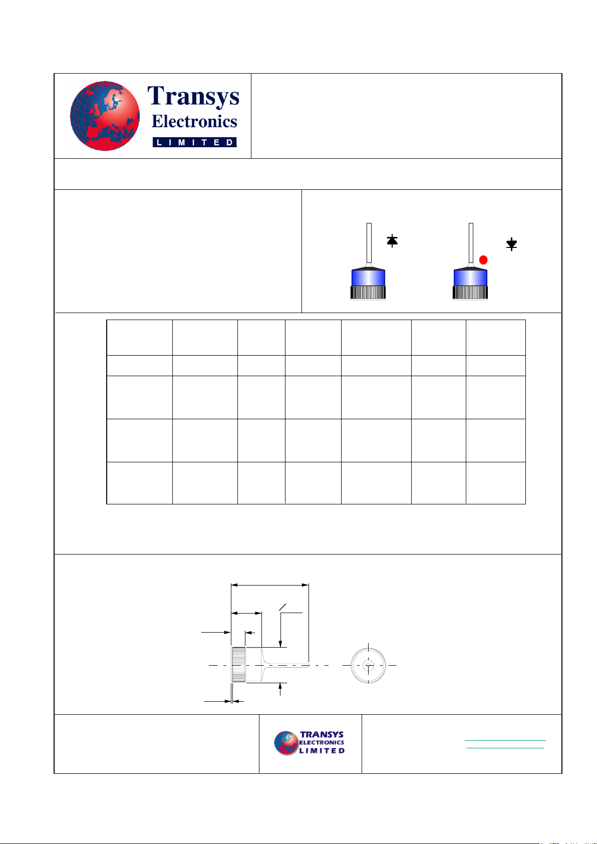
Mechanical Dimensions
Type Number
Breakdown
Voltage
Maximum
Clamping
Forward
Voltage
Leakage
Volt
Volt
nA
Reverse
V
BR
V
F
Reverse
I
R
Maximum
Voltage
V
CL
Volt
Current
Forward
Maximum
I
F (AVG)
Amp
Rectifier/Zener Automotive Alternator Diode
Surge Current
Peak Forward
Non Repetitive
I
FSM
Amp
Maximum Operating Temperature Range
-65 to + 200
Maximum Storage Temperature Range
-65 to + 200
º C
º C
Power cycle requirement.
1. 10,000 cycles
2. I
F
= 200% Rated current
3. Temperature rise 150
4. Excursion rate 37.5 /Minute, +/- 5 /Minute
º C
º C
º C
RZ2524C/A - 25 Amp
RZ3524C/A - 35 Amp
RZ5024C/A - 50 Amp
Pressfit Diode
Maximum
200
@ VR =20 Volt
< 34
@ IR = 2.8 x IF avg
80 µS
< 2% duty Cycle
1.05
@ 100A t = 300 S
< 2% Duty Cycle
24 - 32
@ 100mA
50
µ
200
@ VR =20 Volt
< 34
@ IR = 2.8 x IF avg
80
< 2% duty Cycle
1.05
@ 100A t = 300 S
< 2% Duty Cycle
24 - 32
@ 100mA
35
µ
µS
RZ2524C
RZ2524A
200
@ VR =20 Volt
< 34
@ IR = 2.8 x IF avg
80
< 2% duty Cycle
1.05
@ 75A t = 300 S
< 2% Duty Cycle
24 - 32
@ 100mA
25
400
@ 8.3mS single
half wave.
(Jedec Method)
µ
µS
Transys Electronics LTD
Birmingham UK.
Email: sales@transyselectronics.com
Website: www.transyselectronics.com
Tel: 44 (0) 121 776 6321
Fax 44 (0) 121 776 6997
Anode Base Suffix "A"
30 Typical
9.8-10.2
O 12.75
4.0-4.4
0.8-1.0
+ 0.09
- 0.00
RZ3524C
RZ3524A
RZ5024C
RZ5024A
Cathode Base Suffix "C"
* Visual to Mil Std 750C
* 100 % Tested
Features
* Low Reverse Leakage
* Low Forward Voltage
* Epi Layer for tight control of parameters
* Silicon oxide passivation for superior junction protection
* Load Dump Capability
@ Ta = 150º
C
@ Ta = 150º
C
600
@ 8.3mS single
half wave.
(Jedec Method)
800
@ 8.3mS single
half wave.
(Jedec Method)
Characterisitics
at 25
(Unless stated otherwise)
º C
 Loading...