

Page 1
www.fairchildsemi.com
RC5058
High Performance Programmable Synchronous
DC-DC Controller for Multi-Voltage Platforms
Features
•P rogrammable output for Vcore from 1.3V to 3.5V using
an integrated 5-bit DAC
Controls adjustable linears for Vagp (selectable 1.5V/3.3V),
•
Vclock (2.5V), and Vtt (1.5V) or Vnorthbridge (1.8V)
• Meets VRM specification with as few as 5 capacitors
• Meets 1.550V +40/-70mV over initial tolerance,
temperature and transients
• Remote sense
• Programmable Active Droop™ (Voltage Positioning)
• Drives N-Channel MOSFETs
• Overcurrent protection using MOSFET sensing
• 85% efficiency typical at full load
• Integrated Power Good and Enable/Soft Start functions
• 24 pin SOIC package
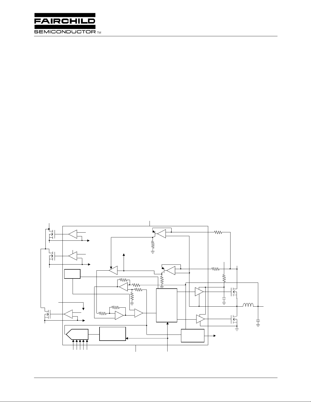
Block Diagram
+3.3V
+1.5V
+2.5V
9
+
10
VCCP
11
+
12
OSC
REF
PWRGD,
OCL
REF
-
PWRGD,
OCL
OCL
VCCA
-
+
Applications
• Power supply for Pentium
• Power supply for Pentium III Whitney Platform
• VRM for Pentium III processor
• Programmable multi-output power supply
®
III Camino Platform
Description
The RC5058 is a synchronous mode DC-DC controller IC
which provides a highly accurate, programmable set of output
voltages for multi-voltage platforms such as the Intel Camino,
and provides a complete solution for the Intel Whitney and other
high-performance processors. The RC5058 features remote
voltage sensing, independently adjustable current limit, and a
proprietary Programmable Active Droop
transient response. The RC5058 uses a 5-bit D/A converter
to program the output voltage from 1.3V to 3.5V. The RC5058
uses a high level of integration to deliver load currents in excess
+5V
21
-
+
-
+
19
18
20
24
1
R
R
S
VCCP
HIDRV
D
+12V
™
for optimal converter
+5V
15
14
+
V
-
5-Bit
DAC
VID2
PWRGD, OCL
VID4
VID3
3.3/1.5V
Pentium is a registered trademark of Intel Corporation. Programmable Active Droop is a trademark of Fairchild Semiconductor.
13
87654
VID0
VID1
-
+
1.24V
Reference
-
+
3
GNDA
Digital
Control
16
ENABLE/SS
Power
Good
2
23
22
17
LODRV
GNDP
PWRGD
VCC
Rev. 1.0.0
Page 2
2
RC5058 PRODUCT SPECIFICATION
of 16A from a 5V source with minimal external circuitry.
Synchronous-mode operation offers optimum efficiency over
the entire specified output voltage range. An on-board precision
low TC reference achieves tight tolerance voltage regulation
without expensive external components, while Programmable
Active Droop
™
permits exact tailoring of voltage for the most
demanding load transients. The RC5058 includes linear regulator
controllers for Vtt termination (1.5V), Vclock (2.5V), and
Vnorthbridge (1.8V) or Vagp (selectable 1.5V/3.3V), each adjustable with an external divider. The RC5058 also offers integrated
functions including Power Good, Output Enable/Soft Start and
current limiting, and is available in a 24 pin SOIC package.
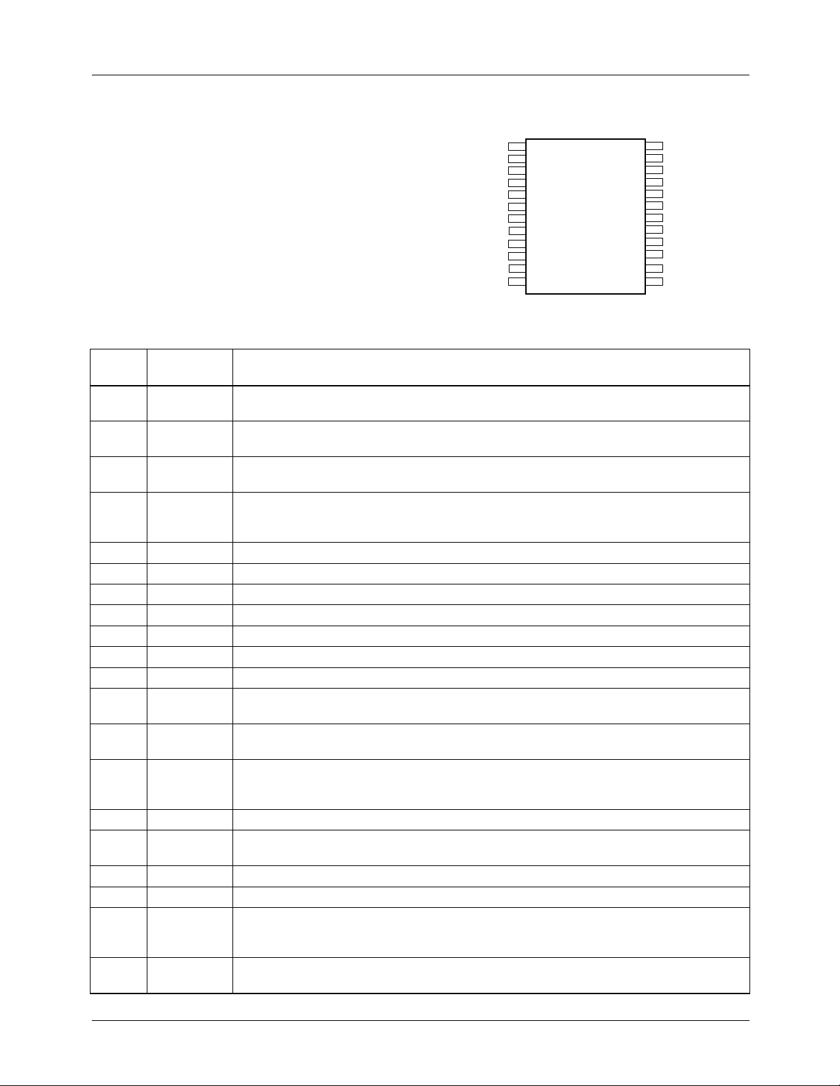
Pin Definitions
Pin
Number Pin Name Pin Function Description
1 HIDRV
2SW
3 GNDA
4-8 VID0-4
9 VTTGATE Gate Driver for VTT Transistor. For 1.5V output.
10 VTTFB
11 VCKGATE Gate Driver for VCK Transistor. For 2.5V output.
12 VCKFB
13 VAGPFB
14 VAGPGATE Gate Driver for VAGP Transistor. For 3.3/1.5V output.
15 TYPEDET Type Detect. Sets 3.3V or 1.5V for AGP.
16 ENABLE/SS Output Enable. A logic LOW on this pin will disable all outputs. An internal current source
17 PWRGD
18 ILIM
19 DROOP
20 VFB
21 VCCA
22 GNDP
23 LODRV
24 VCCP
High Side FET Driver. Connect this pin through a resistor to the gate of an N-channel
MOSFET. The trace from this pin to the MOSFET gate should be <0.5".
High side Driver Source and Low side Driver Drain Switching Node. Together with
DROOP and ILIM pins allows FET sensing for Vcc current.
Analog Ground. Return path for low power analog circuitry. This pin should be
connected to a low impedance system ground plane to minimize ground loops.
Voltage Identification Code Inputs. These open collector/TTL compatible inputs will
program the output voltage over the ranges specified in Table 2. Pull-up resistors are
internal to the controller.
Voltage Feedback for VTT.
Voltage Feedback for VCK.
Voltage Feedback for VAGP.
allows for open collector control. This pin also doubles as soft start for all outputs.
Power Good Flag. An open collector output that will be logic LOW if any output voltage
is more than ±12% outside of the nominal output voltage setpoint.
Vcc Current Feedback. Pin 18 is used in conjunction with pin 2 as the input for the Vcc
current feedback control loop. Layout of these traces is critical to system performance.
See Application Information for details.
Droop set. Use this pin to set magnitude of active droop.
Vcc Voltage Feedback. Pin 20 is used as the input for the Vcc voltage feedback control
loop. See Application Information for details regarding correct layout.
Analog VCC. Connect to system 5V supply and decouple with a 0.1µF ceramic capacitor.
Power Ground. Return pin for high currents flowing in pin 24 (VCCP).
Vcc Low Side FET Driver. Connect this pin through a resistor to the gate of an N-channel
MOSFET for synchronous operation. The trace from this pin to the MOSFET gate should
be <0.5".
Power VCC. For all FET drivers. Connect to system 12V supply through a 33 Ω , and
decouple with a 1µF ceramic capacitor.
Pin Assignments
HIDRV
SW
GNDA
VID4
VID3
VID2
VID1
VID0
VTTGATE
VTTFB
VCKGATE
VCKFB
1
2
3
4
5
6
7
8
9
10
11
12
RC5058
24
23
22
21
20
19
18
17
16
15
14
13
VCCP
LODRV
GNDP
VCCA
VFB
DROOP
ILIM
PWRGD
SS/ENABLE
TYPEDET
VAGPGATE
VAGPFB
REV. 1.0.0 6/30/00
Page 3
PRODUCT SPECIFICATION RC5058
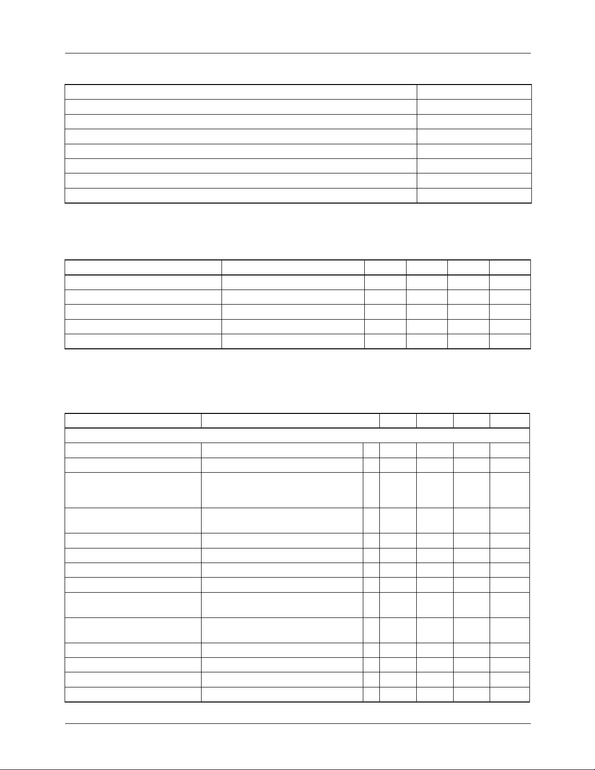
Absolute Maximum Ratings
Supply Voltage VCCA to GND 13.5V
Supply Voltage VCCP to GND 15V
Voltage Identification Code Inputs, VID0-VID4 VCCA
All Other Pins 13.5V
Junction Temperature, T
J
150°C
Storage Temperature -65 to 150°C
Lead Soldering Temperature, 10 seconds 300°C
Thermal Resistance Junction-to-ambient, Θ
Note:
1. Component mounted on demo board in free air.
JA
1
75°C/W
Recommended Operating Conditions
Parameter Conditions Min. Typ. Max. Units
Supply Voltage VCCA 4.5 5 5.25 V
Input Logic HIGH 2.0 V
Input Logic LOW 0.8 V
Ambient Operating Temperature 0 70 °C
Output Driver Supply, VCCP 10.8 12 13.2 V
Electrical Specifications
(V
= 5V, V
CCA
The • denotes specifications which apply over the full operating temperature range.
Parameter Conditions Min. Typ. Max. Units
VCC Regulator
Output Voltage See Table 1 • 1.3 3.5 V
Output Current 18 A
Initial Voltage Setpoint I
Output Temperature Drift T
Line Regulation V
Internal Droop Impedance I
Maximum Droop 60 mV
Output Ripple 20MHz BW, I
Total Output Variation,
Steady State
Total Output Variation,
Transient
Short Circuit Detect Current • 45 50 60 µA
Efficiency I
Output Driver Rise & Fall Time See Figure 3 50 nsec
Output Driver Deadtime See Figure 3 50 nsec
CCP
2
= 12V, V
1
= 2.0V, and T
OUT
= +25°C using circuit in Figure 1 unless otherwise noted.)
A
= 0.8A,V
LOAD
= 0 to 70°C,V
A
= 4.75V to 5.25V • -4 mV/V
IN
= 0.8A to 12.5A 13.0 14.4 15.8 K Ω
LOAD
V
= 2.000V
OUT
V
= 1.550V
OUT
I
= 0.8A to 18A, V
LOAD
= 18A, V
LOAD
= 2.400V
OUT
V
= 2.000V
OUT
V
= 1.550V
OUT
= 2.000V
OUT
V
= 1.550V
OUT
= 18A 11 mVpk
LOAD
3
= 2.000V
OUT
V
= 1.550V
OUT
= 2.0V 85 %
OUT
3
2.397
2.000
1.550
•
•
••1.940
1.480
••1.900
1.480
2.424
2.020
1.565
+8
+6
2.454
2.040
1.580
2.070
1.590
2.100
1.590
V
V
V
mV
mV
V
V
REV. 1.0.0 6/30/00
3
Page 4
4
≤
≤
≤
≤
RC5058 PRODUCT SPECIFICATION
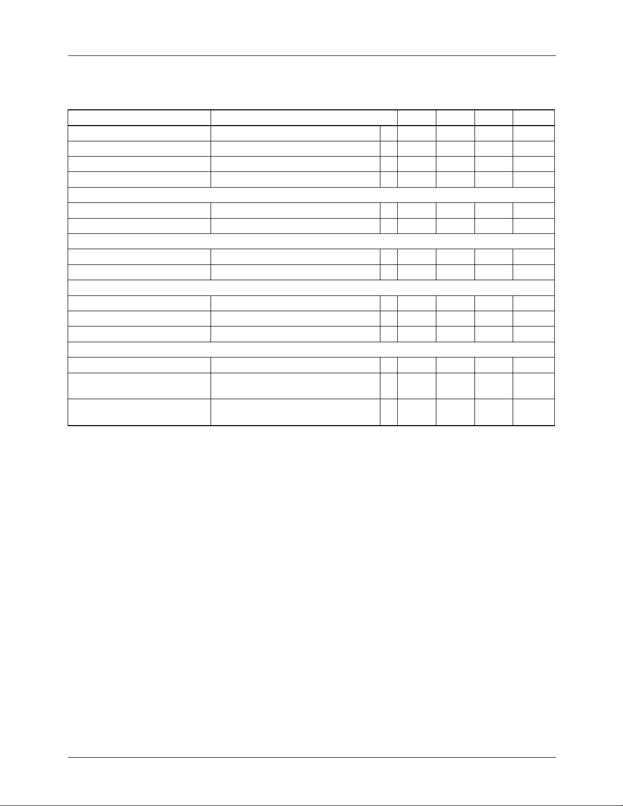
Electrical Specifications
(V
CCA
= 5V, V
CCP
= 12V, V
OUT
(Continued)
= 2.0V, and T
= +25°C using circuit in Figure 1 unless otherwise noted.)
A
The • denotes specifications which apply over the full operating temperature range.
Parameter Conditions Min. Typ. Max. Units
Duty Cycle 0 100 %
5V UVLO • 3.74 4 4.26 V
12V UVLO • 7.65 8.5 9.35 V
Soft Start Current • 5 10 17 µA
VTT Linear Regulator
Output Voltage I
2A • 1.455 1.5 1.545 V
LOAD
Under Voltage Trip Level Over Current 80 %V
VCLK Linear Regulator
Output Voltage I
2A • 2.375 2.5 2.625 V
LOAD
Under Voltage Trip Level Over Current 80 %V
VAGP Linear Regulator
Output Voltage I
Output Voltage I
2A, TYPEDET=0V • 1.425 1.5 1.575 V
LOAD
2A, TYPEDET=OPEN • 3.135 3.3 3.465 V
LOAD
Under Voltage Trip Level Over Current 80 %V
Common Functions
Oscillator Frequency • 255 310 345 kHz
PWRGD Threshold Logic HIGH, All Outputs
Linear Regulator Under Voltage
Logic LOW, Any Output
Over Current 30 µsec
•
92
•
88
108
112
Delay Time
Notes:
1. Steady State Voltage Regulation includes Initial Voltage Setpoint, Droop, Output Ripple and Output Temperature Drift and is
measured at the converter’s VFB sense point.
2. As measured at the converter’s VFB sense point. For motherboard applications, the PCB layout should exhibit no more than
0.5m Ω trace resistance between the converter’s output capacitors and the CPU. Remote sensing should be used for optimal
performance.
3. Using the VFB pin for remote sensing of the converter’s output at the load, the converter will be in compliance with Intel’s VRM 8.4
specification of +50, –80mV. If Intel specifications on maximum plane resistance from the converter’s output capacitors to the CPU
are met, the specification of +40, –70mV at the capacitors will also be met.
%V
O
O
O
OUT
REV. 1.0.0 6/30/00
Page 5
PRODUCT SPECIFICATION RC5058
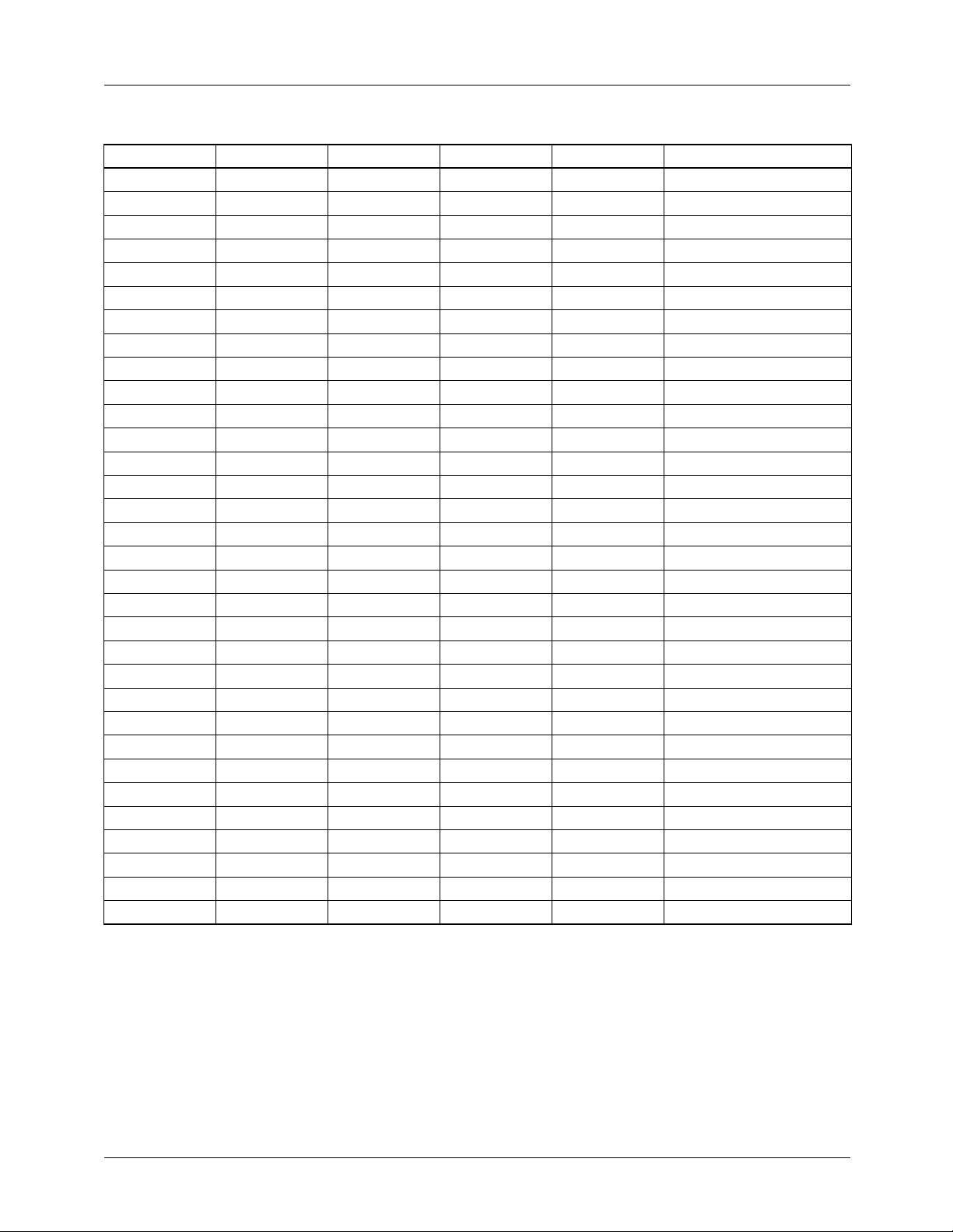
Table 1. Output Voltage Programming Codes
VID4 VID3 VID2 VID1 VID0 Nominal V
01111 1.30V
01110 1.35V
01101 1.40V
01100 1.45V
01011 1.50V
01010 1.55V
01001 1.60V
01000 1.65V
00111 1.70V
00110 1.75V
00101 1.80V
00100 1.85V
00011 1.90V
00010 1.95V
00001 2.00V
00000 2.05V
11111 2.0V
11110 2.1V
11101 2.2V
11100 2.3V
11011 2.4V
11010 2.5V
11001 2.6V
11000 2.7V
10111 2.8V
10110 2.9V
10101 3.0V
10100 3.1V
10011 3.2V
10010 3.3V
10001 3.4V
10000 3.5V
OUT
Note:
1. 0 = processor pin is tied to GND.
1 = processor pin is open.
REV. 1.0.0 6/30/00
5
Page 6
RC5058 PRODUCT SPECIFICATION
V
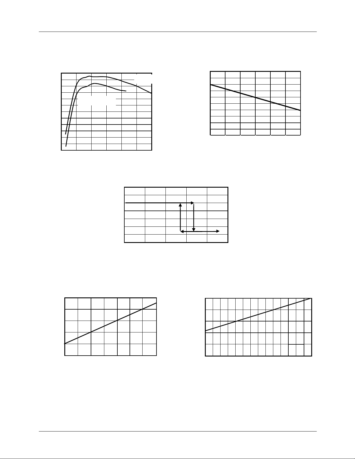
Typical Operating Characteristics
(V
= 5V, V
CCA
88
86
84
82
80
78
76
Efficiency (%)
74
72
70
68
66
64
0 3 6 9 12 15 18
= 12V, and T
CCP
V
Efficiency vs. Output Current
CPU
V
= 1.550V
OUT
Output Current (A)
= +25°C using circuits in Figure 1, unless otherwise noted.)
A
Droop, V
2.04
V
= 2.000
OUT
2.03
2.02
2.01
2.00
1.99
(V)
1.98
OUT
V
1.97
1.96
1.95
1.94
0 3 6 9 12 15 18
= 2.0V, RD = 8K Ω
CPU
Output Current (A)
6
CPU Output Voltage vs. Output Current
3.5
3.0
2.5
2.0
(V)
OUT
1.5
Output Programming, VID4 = 0
2.1
1.9
1.7
(V)
1.5
CPU
V
1.3
V
1.0
0.5
0
0 5 10 15 20 25
Output Current (A)
3.5
3.0
2.5
(V)
2.0
CPU
V
1.5
Output Programming, VID4 = 1
1.1
1.30 1.40 1.50 1.60 1.70 1.80 1.90 2.00
DAC Setpoint
1.0
2.1 2.2 2.3 2.4 2.5 2.6 2.7 2.8 2.9 3.0 3.1 3.2. 3.3 3.4 3.5
DAC Setpoint
REV. 1.0.0 6/30/00
Page 7
PRODUCT SPECIFICATION RC5058
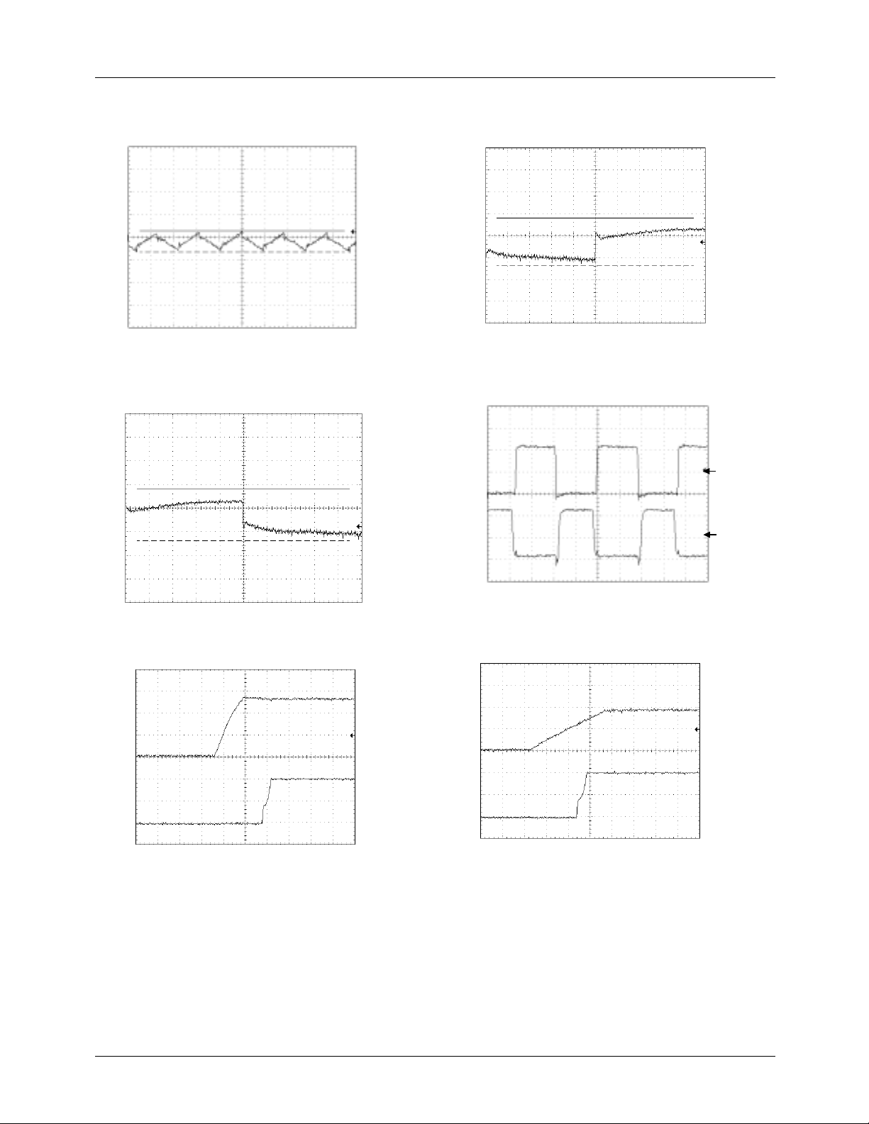
Typical Operating Characteristics
Output Ripple, 2.0V @ 18A
(20mV/div)
CPU
V
Time (1µs/div)
Transient Response, 0.5A to 12.5A
1.590V
(50mV/div)
CPU
V
1.550V
1.480V
(continued)
Transient Response, 12.5A to 0.5A
(50mV/div)
CPU
V
Switching Waveforms, 18A Load
5V/div 5V/div
1.590V
1.550V
1.480V
Time (100µs/div)
HIDRV
pin
LODRV
pin
(2V/div)
IN
(1V/div) V
CPU
V
Time (100µs/div)
Output Startup, System Power-up
Time (10ms/div)
Time (1µs/div)
Output Startup from Enable
(1V/div) ENABLE (2V/div)
CPU
V
Time (10ms/div)
REV. 1.0.0 6/30/00
7
Page 8
RC5058 PRODUCT SPECIFICATION
Typical Operating Characteristics (continued)
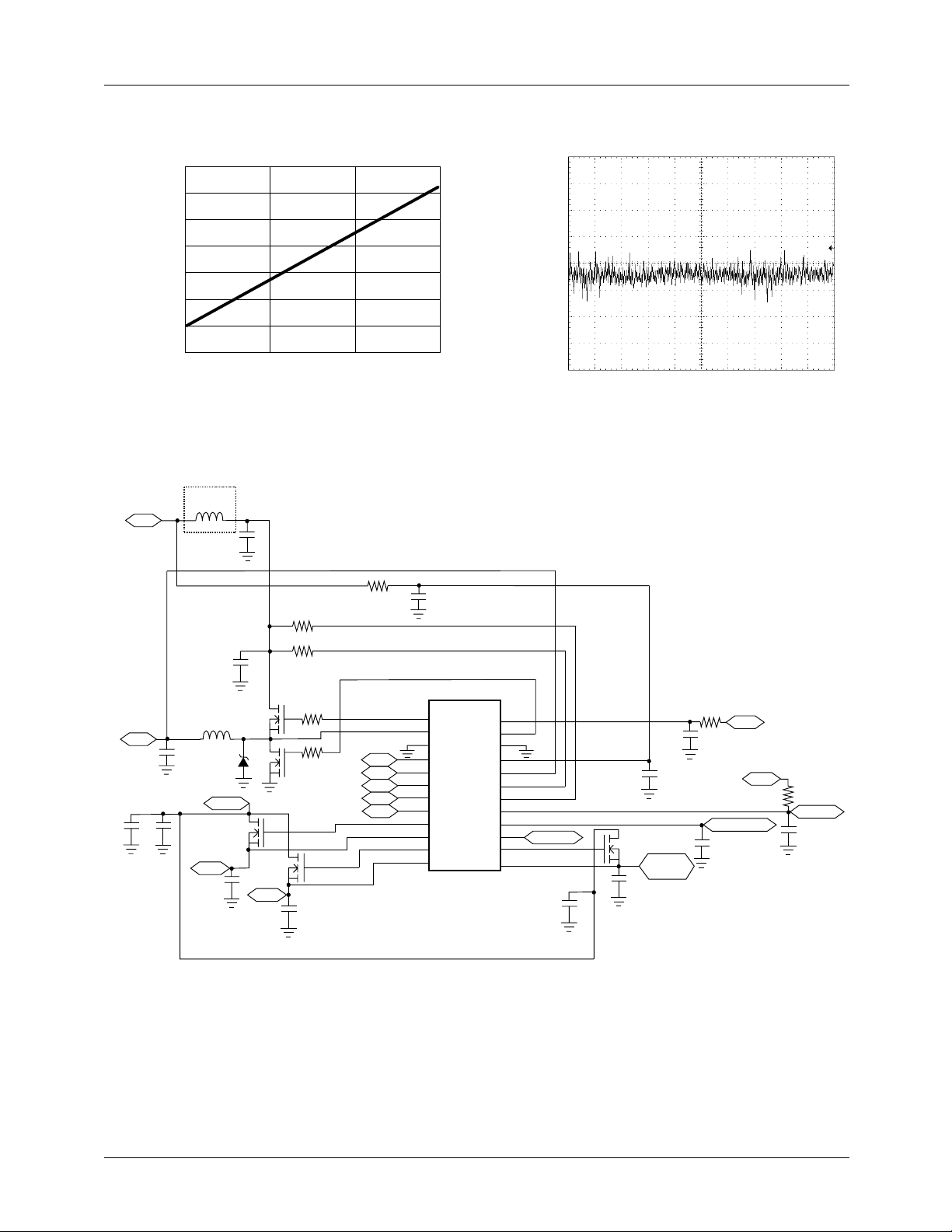
Linear Regulator Noise
2.042
2.040
2.038
(10mV/div)
OUT
(V)
CPU
V
2.036
2.034
2.030
2.028
2.026
0 25 70 100
Application Circuit
L1
+5V
(Optional)
VO
C
OUT
C10 C11
*
L2
3.3V IN
1.5V†
C8
Temperature (°C)
CIN*
C2
Q1
Q2
D1
Q3
2.5V†
AC COUPLED V
Time (100µs/div)
R7
R5
R2
R3
Q4
C9
R6
VID4
VID3
VID2
VID1
VID0
C1
C4
R1
+12V
C5
ENABLE/SS
VCC
R4
PWRGD
C6
, C
IN
OUT
,
1
2
3
4
U1
5
RC5058
6
7
8
9
10
11
12
24
23
22
21
20
19
18
17
16
15
14
13
TYPEDET
C12
C3
Q5
3.3/1.5V
(AGP)†
C7
* Refer to Appendix for values of C
R5 and R7.
† Adjustable with an external divider.
Figure 1. Typical Application Circuit
(Worst Case Analyzed! See Appendix for Details)
8 REV. 1.0.0 6/30/00
Page 9

PRODUCT SPECIFICATION RC5058
Table 2. RC5058 Application Bill of Materials
(Components based on Worst Case Analysis—See Appendix for Details)
Reference Manufacturer Part # Quantity Description Requirements/Comments
C1 AVX
TAJB475M010R5
C2, C5 Panasonic
ECU-V1C105ZFX
C3-4,C6 Panasonic
ECU-V1H104ZFX
C7-9 Sanyo
6MV1000FA
C10-12 Any 3 22µF, 6.3V Capacitor Low ESR
C
IN
Sanyo
10MV1200GX
C
OUT
Sanyo
6MV1500GX
D1 Motorola
MBRD835L
L1 Any Optional 2.5µH, 8A Inductor DCR ~ 10mΩ
L2 Any 1 1.3µH, 20A Inductor DCR ~ 2mΩ
Q1 Fairchild
FDB6030L
Q2 Fairchild
FDB7030BL
Q3-5 Fairchild
FDB4030L
R1 Any 1 33Ω
R2-3 Any 2 4.7Ω
R4 Any 1 10KΩ
R5 Any 1 *
R6 Any 1 10Ω
R7 Any 1 *
U1 Fairchild
RC5058M
1 4.7µF, 10V Capacitor
2 1µF, 16V Capacitor
3 100nF, 50V Capacitor
3 1000µF, 6.3V Electrolytic
* 1200µF, 10V Electrolytic I
RMS
= 2A
* 1500µF, 6.3V Electrolytic ESR ≤ 44mΩ
1 8A Schottky Diode
See Note 1.
1 N-Channel MOSFET R
DS(ON)
= 20mΩ @
VGS = 4.5V See Note 2.
1 N-Channel MOSFET R
V
= 10mΩ @
DS(ON)
= 4.5V See Note 2.
GS
3 N-Channel MOSFET
1 DC/DC Controller
Notes:
1. Inductor L1 is recommended to isolate the 5V input supply from noise generated by the MOSFET switching, and to comply
with Intel dI/dt requirements. L1 may be omitted if desired.
2. For 17.4A designs using the TO-220 MOSFETs, heatsinks with thermal resistance ΘSA < 20°C/W should be used. For designs
using the TO-263 MOSFETs, adequate copper area should be used. For details and a spreadsheet on MOSFET selections,
refer to Applications Bulletins AB-8 and AB-15.
*Refer to Appendix for values.
REV. 1.0.0 6/30/00 9
Page 10

RC5058 PRODUCT SPECIFICATION
L1
+5V
(Optional)
CIN*
VO
C
*
OUT
C10 C11
R7
R5
C2
Q1
L2
R8
Q2
D1
3.3V IN
Q3
1.5V†
C8
2.5V†
R2
R3
Q4
C9
R6
VID4
VID3
VID2
VID1
VID0
C1
C4
R1
+12V
C5
ENABLE/SS
VCC
OUT
R4
PWRGD
C6
and CIN.
1
2
3
4
U1
5
RC5058
6
7
8
9
10
11
12
24
23
22
21
20
19
18
17
16
15
14
13
TYPEDET
C12
C3
Q5
3.3/1.5V
(AGP)†
C7
*Refer to Table 4 for values of C
† Adjustable with an external divider.
Figure 2. Application Circuit for Coppermine/Camino Motherboards
(Typical Design)
10 REV. 1.0.0 6/30/00
Page 11

PRODUCT SPECIFICATION RC5058
Table 3. RC5058 Application Bill of Materials for Intel Coppermine/Camino Motherboards
(Typical Design)
Reference Manufacturer Part # Quantity Description Requirements/Comments
C1 AVX
TAJB475M010R5
C2, C5 Panasonic
ECU-V1C105ZFX
C3-4,C6 Panasonic
ECU-V1H104ZFX
C7-9 Sanyo
6MV1000FA
C10-12 Any 3 22µF, 6.3V Capacitor Low ESR
C
IN
Sanyo
10MV1200GX
C
OUT
Sanyo
6MV1500GX
D1 Motorola
MBRD835L
L1 Any Optional 2.5µH, 5A Inductor DCR ~ 10mΩ
L2 Any 1 1.3µH, 15A Inductor DCR ~ 3mΩ
Q1 Fairchild
FDB6030L
Q2 Fairchild
FDB7030BL
Q3-5 Fairchild
FDB4030L
R1 Any 1 33Ω
R2-3 Any 2 4.7Ω
R4 Any 1 10KΩ
R5, R7 Any 2 6.24KΩ
R6 Any 1 10Ω
R8 N/A 1 3.0mΩ PCB Trace Resistor
U1 Fairchild
RC5058M
1 4.7µF, 10V Capacitor
2 1µF, 16V Capacitor
3 100nF, 50V Capacitor
3 1000µF, 6.3V Electrolytic
3 1200µF, 10V Electrolytic I
RMS
= 2A
12 1500µF, 6.3V Electrolytic ESR ≤ 44mΩ
1 8A Schottky Diode
See Note 1.
1 N-Channel MOSFET R
V
1 N-Channel MOSFET R
V
= 20mΩ @
DS(ON)
= 4.5V See Note 2.
GS
= 10mΩ @
DS(ON)
= 4.5V See Note 2.
GS
3 N-Channel MOSFET
1 DC/DC Controller
Notes:
1. Inductor L1 is recommended to isolate the 5V input supply from noise generated by the MOSFET switching, and to comply
with Intel dI/dt requirements. L1 may be omitted if desired.
2. For 12.5A designs using the TO-220 MOSFETs, heatsinks with thermal resistance Θ
designs using the TO-263 MOSFETs, adequate copper area should be used. For details and a spreadsheet on MOSFET
selections, refer to Applications Bulletins AB-8 and AB-15.
REV. 1.0.0 6/30/00 11
< 20°C/W should be used. For
SA
Page 12

RC5058 PRODUCT SPECIFICATION
Test Parameters
t
R
5V
2V
t
DT
2V
Figure 3. Ouput Drive Timing Diagram
5V
2V
t
F
HIDRV
to SW
t
DT
2V
LODRV
Application Information
The RC5058 Controller
The RC5058 is a programmable synchronous DC-DC controller IC. When designed around the appropriate external
components, the RC5058 can be configured to deliver more
than 16A of output current, as appropriate for the Katmai and
Coppermine and other processors. The RC5058 functions as
a fixed frequency PWM step down regulator.
Main Control Loop
Refer to the RC5058 Block Diagram on page 1. The RC5058
implements “summing mode control”, which is different from
both classical voltage-mode and current-mode control. It
provides superior performance to either by allowing a large
converter bandwidth over a wide range of output loads.
The control loop of the regulator contains two main sections:
the analog control block and the digital control block. The
analog section consists of signal conditioning amplifiers feeding
into a comparator which provides the input to the digital control
block. The signal conditioning section accepts input from the
DROOP (current feedback) and VFB (voltage feedback) pins
and sets up two controlling signal paths. The first, the voltage
control path, amplifies the difference between the VFB signal
and the reference voltage from the DAC and presents the
output to one of the summing amplifier inputs. The second,
current control path, takes the difference between the DROOP
and SW pins when the high-side MOSFET is on, reproducing
the voltage across the MOSFET and thus the input current; it
presents the resulting signal to another input of the summing
amplifier. These two signals are then summed together. This
output is then presented to a comparator looking at the oscillator
ramp, which provides the main PWM control signal to the
digital control block.
The digital control block takes the analog comparator input
and the main clock signal from the oscillator to provide the
appropriate pulses to the HIDRV and LODRV output pins.
These two outputs control the external power MOSFETs.
High Current Output Drivers
The RC5058 contains two identical high current output drivers
that utilize high speed bipolar transistors in a push-pull configuration. The drivers’ power and ground are separated from
the chip’s power and ground for switching noise immunity.
The power supply pin, VCCP, is supplied from an external
12V source through a series 33Ω resistor. The resulting voltage is sufficient to provide the gate to source drive to the
external MOSFETs required in order to achieve a low R
DS,ON
Internal Voltage Reference
The reference included in the RC5058 is a precision band-gap
voltage reference. Its internal resistors are precisely trimmed
to provide a near zero temperature coefficient (TC). Based on
the reference is the output from an integrated 5-bit DAC. The
DAC monitors the 5 voltage identification pins, VID0-4. When
the VID4 pin is at logic HIGH, the DAC scales the reference
voltage from 2.0V to 3.5V in 100mV increments. When VID4
is pulled LOW, the DAC scales the reference from 1.30V to
2.05V in 50mV increments. All VID codes are available, including those below 1.80V.
Power Good (PWRGD)
The RC5058 Power Good function is designed in accordance
with the Pentium II and III DC-DC converter specifications
and provides a continuous voltage monitor on the VFB pin.
The circuit compares the VFB signal to the VREF voltage
and outputs an active-low interrupt signal to the CPU should
the power supply voltage deviate more than ±12% of its
nominal setpoint. Power Good outputs an open collector
high when the output voltage is within ±8% of its nominal
setpoint. The Power Good flag provides no other control
function to the RC5058.
Output Enable/Soft Start (ENABLE/SS)
The RC5058 will accept an open collector/TTL signal for
controlling the output voltage. The low state disables the output
voltage. When disabled, the PWRGD output is in the low state.
Even if an enable is not required in the circuit, this pin should
have attached a capacitor (typically 100nF) to softstart the
switching. A larger value may occasionally be required if the
converter has a very large capacitor at its output.
Over-Voltage Protection
The RC5058 constantly monitors the output voltage for protection against over-voltage conditions. If the voltage at the VFB
pin exceeds the selected program voltage, an over-voltage
condition is assumed and the RC5058 disables the output
drive signal to the external high-side MOSFET. The DC-DC
converter returns to normal operation after the output voltage
returns to normal levels.
.
There is an additional comparator in the analog control section
whose function is to set the point at which the RC5058 current
limit comparator disables the output drive signals to the
external power MOSFETs.
12 REV. 1.0.0 6/30/00
Oscillator
The RC5058 oscillator section uses a fixed frequency of
operation of 300KHz.
Page 13
PRODUCT SPECIFICATION RC5058
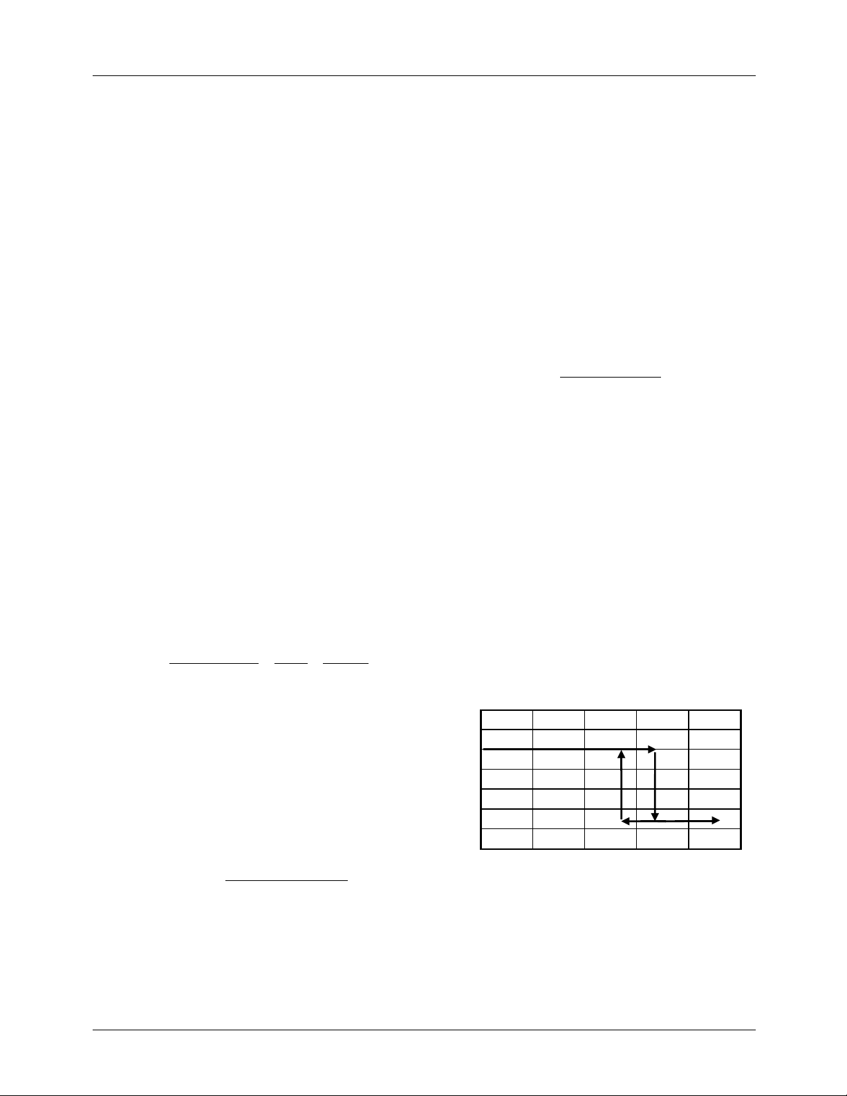
95%).
Design Considerations and Component
Selection
Additional information on design and component selection
may be found in Fairchild’s Application Note 57.
MOSFET Selection
This application requires N-channel Logic Level Enhancement
Mode Field Effect Transistors. Desired characteristics are as
follows:
• Low Static Drain-Source On-Resistance, R
DS,ON
< 20mΩ
(lower is better)
• Low gate drive voltage, VGS = 4.5V rated
• Power package with low Thermal Resistance
• Drain-Source voltage rating > 15V.
The on-resistance (R
is the primary parameter for
DS,ON)
MOSFET selection. The on-resistance determines the power
dissipation within the MOSFET and therefore significantly
affects the efficiency of the DC-DC Converter. For details
and a spreadsheet on MOSFET selection, refer to Applications Bulletin AB-8.
Inductor Selection
Choosing the value of the inductor is a tradeoff between
allowable ripple voltage and required transient response. The
system designer can choose any value within the allowed
minimum to maximum range in order to either minimize ripple
or maximize transient performance. The first order equation
(close approximation) for minimum inductance is:
(V
– V
)
in
L
=
min
out
f
V
out
x
V
where:
Vin = Input Power Supply
= Output Voltage
V
out
f = DC/DC converter switching frequency
ESR = Equivalent series resistance of all output capacitors in
parallel
V
= Maximum peak to peak output ripple voltage budget.
ripple
The first order equation for maximum allowed inductance is:
(V
– V
in
L
max
2C
=
O
out
2
I
pp
where:
Co = The total output capacitance
Ipp = Maximum to minimum load transient current
Vtb = The output voltage tolerance budget allocated to load
transient
Dm = Maximum duty cycle for the DC/DC converter (usually
x
in
) Dm V
ESR
V
ripple
tb
Some margin should be maintained away from both L
L
. Adding margin by increasing L almost always adds
max
min
and
expense since all the variables are predetermined by system
performance except for C
, which must be increased to
O
increase L. Adding margin by decreasing L can be done by
purchasing capacitors with lower ESR. The RC5058 provides significant cost savings for the newer CPU systems
that typically run at high supply current.
RC5058 Short Circuit Current Characteristics
The RC5058 protects against output short circuit on the core
supply by turning off both the high-side and low-side
MOSFETs and resetting softstart. The short circuit limit is
set with the RS resistor, as given by the formula
I
*R
SC
R
=
S
with I
R
DS,on
≈ 50µA, I
Detect
the high-side MOSFET’s on resistance. Remember to
is the desired current limit, and
SC
make the RS large enough to include the effects of initial tolerance and temperature variation on the MOSFET’s R
Alternately, use of a sense resistor in series with the source
of the MOSFET eliminates this source of inaccuracy in the
current limit. The value of RS should be less than 8.3KΩ. If a
greater value is necessary, a lower R
be used instead.
As an example, Figure 4 shows the typical characteristic of
the DC-DC converter circuit with an FDB6030L high-side
MOSFET (RDS = 20mΩ maximum at 25°C * 1.25 at 75°C =
25mΩ) and a 8.2KΩ RS.
CPU Output Voltage vs. Output Current
3.5
3.0
2.5
2.0
(V)
OUT
1.5
V
1.0
0.5
0
0 5 10 15 20 25
Figure 4. RC5058 Short Circuit Characteristic
The converter exhibits a normal load regulation characteristic
until the voltage across the MOSFET exceeds the internal
short circuit threshold of 50µA * 8.2KΩ = 410mV, which
occurs at 410mV/25mΩ = 16.4A. (Note that this current limit
level can be as high as 410mV/15mΩ = 27A, if the MOSFET
has typical R
rather than maximum, and is at 25°C).
DS,on
I
Detect
DS, on
MOSFET should
DS,on
DS,on
.
REV. 1.0.0 6/30/00 13
Page 14

RC5058 PRODUCT SPECIFICATION
converter, and to limit the inrush current into the input capac-
itors during power up. A value of 2.5µH is recommended.
At this point, the internal comparator trips and signals the controller to discharge the softstart capacitor. This causes a drastic
reduction in the output voltage as the load regulation collapses
into the short circuit control mode. With a 40mΩ output short,
the voltage is reduced to 16.4A * 40mΩ = 650mV. The output
voltage does not return to its nominal value until the output
current is reduced to a value within the safe operating ranges
for the DC-DC converter.
It is necessary to have some low ESR aluminum electrolytic
capacitors at the input to the converter. These capacitors
deliver current when the high side MOSFET switches on.
Figure 5 shows 3 x 1000µF, but the exact number required
will vary with the speed and type of the processor. For the
top speed Katmai and Coppermine, the capacitors should be
rated to take 9A and 6A of ripple current respectively.
Capacitor ripple current rating is a function of temperature,
If any of the linear regulator outputs are loaded heavily
enough that their output voltage drops below 80% of nominal
for >30µsec, all RC5058 outputs, including the switcher, are
shut off and remain off until power is recycled.
and so the manufacturer should be contacted to find out the
ripple current rating at the expected operational temperature.
For details on the design of an input filter, refer to Applica-
tions Bulletin AB-15.
Schottky Diode Selection
The application circuit of Figure 1 shows a Schottky diode,
D1, which is used as a free-wheeling diode to assure that the
body-diode in Q2 does not conduct when the upper MOSFET
is turning off and the lower MOSFET is turning on. It is
undesirable for this diode to conduct because its high forward
voltage drop and long reverse recovery time degrades efficiency,
and so the Schottky provides a shunt path for the current.
Since this time duration is very short, the selection criterion
for the diode is that the forward voltage of the Schottky at
the output current should be less than the forward voltage of
the MOSFET’s body diode.
Output Filter Capacitors
The output bulk capacitors of a converter help determine its
output ripple voltage and its transient response. It has already
been seen in the section on selecting an inductor that the ESR
helps set the minimum inductance, and the capacitance value
helps set the maximum inductance. For most converters,
however, the number of capacitors required is determined by
the transient response and the output ripple voltage, and these
are determined by the ESR and not the capacitance value.
That is, in order to achieve the necessary ESR to meet the
transient and ripple requirements, the capacitance value
required is already very large.
The most commonly used choice for output bulk capacitors is
aluminum electrolytics, because of their low cost and low ESR.
The only type of aluminum capacitor used should be those that
have an ESR rated at 100kHz. Consult Application Bulletin
AB-14 for detailed information on output capacitor selection.
2.5µH
™
Vin
1000µF, 10V
Electrolytic
5V
0.1µF
Figure 5. Input Filter
Programmable Active Droop
The RC5058 includes Programmable Active Droop™: as the
output current increases, the output voltage drops, and the
amount of this drop is user adjustable. This is done in order
to allow maximum headroom for transient response of the
converter. The current is typically sensed by measuring the
voltage across the R
of the high-side MOSFET during
DS,on
its on time, as shown in Figure 1.
To program the amount of droop, use the formula
where I
14.4KΩ *I
R
D
is the current at which the droop occurs, and R
max
V
max
Droop
*R
*18
sense
sense
is the resistance of the current sensor, either the source resistor
or the high-side MOSFET’s on-resistance. For example, to
get 30mV of droop with a maximum output current of 12.5A
and a 10mΩ sense resistor, use RD = 14.4KΩ * 12.5A * 10mΩ/
(30mV * 18) = 3.33KΩ. Further details on use of the
Programmable Active Droop™ may be found in Applications
Bulletin AB-24.
The output capacitance should also include a number of
small value ceramic capacitors placed as close as possible to
the processor; 0.1µF and 0.01µF are recommended values.
Input Filter
The DC-DC converter design may include an input inductor
between the system +5V supply and the converter input as
shown in Figure 5. This inductor serves to isolate the +5V
Remote Sense
The RC5058 offers remote sense of the output voltage to
minimize the output capacitor requirements of the converter.
It is highly recommended that the remote sense pin, Pin 20,
be tied directly to the processor power pins, so that the
effects of power plane impedance are eliminated. Further
details on use of the remote sense feature of the RC5058 may
be found in Applications Bulletin AB-24.
supply from the noise in the switching portion of the DC-DC
14 REV. 1.0.0 6/30/00
Page 15
PRODUCT SPECIFICATION RC5058
traces that connect to pins 3, 20 and 21.
Adjusting the Linear Regulators’ Output Voltages
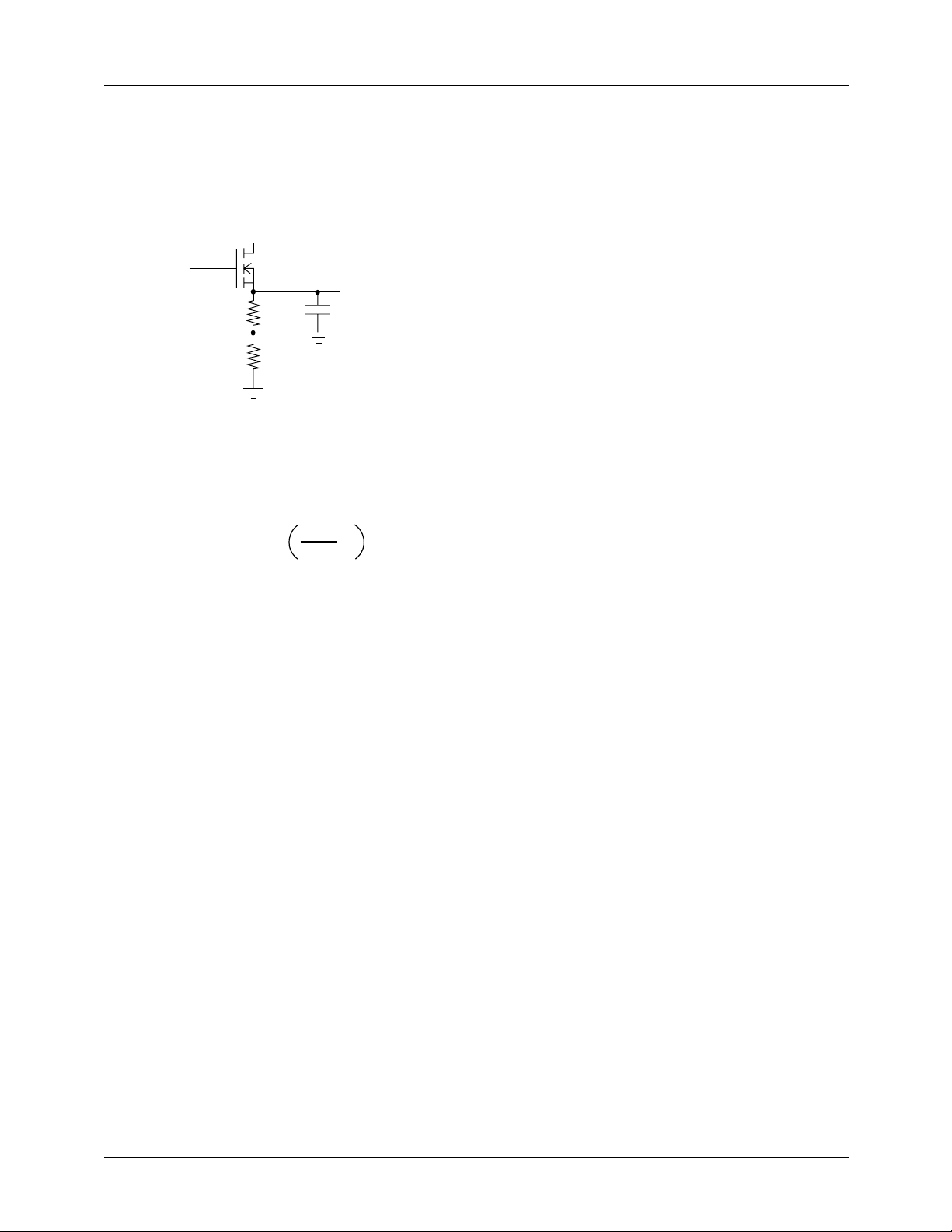
Any or all of the linear regulators’ outputs may be adjusted
high to compensate for voltage drop along traces, as shown
in Figure 6.
VGATE
VOUT
R
VFB
10KΩ
Figure 6. Adjusting the Output Voltage of the Linear
Regulator
The resistor value should be chosen as
V
R 10KΩ* –1
=
out
V
nom
For example, to get the VTT voltage to be 1.55V instead of
1.50V, use R = 10KΩ * [(1.55/1.50) – 1] = 333Ω.
Using the RC5058 for Vnorthbridge = 1.8V
In some motherboards, Intel requires that the AGP power can not
be greater than 2.2V while the chipset voltage (Vnorthbridge =
1.8V) is less than 1.0V. The RC5058 can accomplish this by
using the VTT regulator to generate Vnorthbridge. Use the circuit
in Figure 6 with R = 2KΩ. Since the linear regulators on the
RC5058 all rise proportionally to one another, when Vnorthbridge = 1.0V, Vagp = 1.8V, meeting the Intel requirement.
• Place the 0.1µF decoupling capacitors as close to the
RC5058 pins as possible. Extra lead length on these
reduces their ability to suppress noise.
• Each VCC and GND pin should have its own via to the
appropriate plane. This helps provide isolation between pins.
• Place the MOSFETs, inductor, and Schottky as close
together as possible for the same reasons as in the first
bullet above. Place the input bulk capacitors as close to
the drains of the high side MOSFETs as possible. In
addition, placement of a 0.1µF decoupling cap right on
the drain of each high side MOSFET helps to suppress
some of the high frequency switching noise on the input
of the DC-DC converter.
• Place the output bulk capacitors as close to the CPU as
possible to optimize their ability to supply instantaneous
current to the load in the event of a current transient.
Additional space between the output capacitors and the
CPU will allow the parasitic resistance of the board traces
to degrade the DC-DC converter’s performance under
severe load transient conditions, causing higher voltage
deviation. For more detailed information regarding
capacitor placement, refer to Application Bulletin AB-5.
• A PC Board Layout Checklist is available from Fairchild
Applications. Ask for Application Bulletin AB-11.
Additional Information
For additional information contact Fairchild Semiconductor at
http://www.fairchildsemi.com/cf/tsg.htm or contact an authorized representative in your area.
PCB Layout Guidelines
• Placement of the MOSFETs relative to the RC5058 is
critical. Place the MOSFETs such that the trace length of
the HIDRV and LODRV pins of the RC5058 to the FET
gates is minimized. A long lead length on these pins will
cause high amounts of ringing due to the inductance of the
trace and the gate capacitance of the FET. This noise radiates
throughout the board, and, because it is switching at such
a high voltage and frequency, it is very difficult to suppress.
• In general, all of the noisy switching lines should be kept
away from the quiet analog section of the RC5058. That
is, traces that connect to pins 1, 2, 23, and 24 (HIDRV, SW,
LODRV and VCCP) should be kept far away from the
REV. 1.0.0 6/30/00 15
Page 16

RC5058 PRODUCT SPECIFICATION
Appendix
Worst-Case Formulae for the Calculation of
Cin, Cout , R5, R7 and Roffset
Figure 1 only)
The following formulae design the RC5058 for worst-case
operation, including initial tolerance and temperature dependence
of all of the IC parameters (initial setpoint, reference tolerance
and tempco, internal droop impedance, current sensor gain),
the initial tolerance and temperature dependence of the MOSFET,
and the ESR of the capacitors. The following information
must be provided:
V
, the value of the positive static voltage limit;
S+
|, the absolute value of the negative static voltage limit;
|V
S-
V
, the value of the positive transient voltage limit;
T+
|VT-|, the absolute value of the negative transient voltage limit;
IO, the maximum output current;
V
, the nominal output voltage;
nom
Vin, the input voltage (typically 5V);
I
, the ripple current rating of the input capacitors, per cap
rms
(2A for the Sanyo parts shown in this datasheet);
RD, the resistance of the current sensor (usually the MOSFET);
(Circuits similar to
The value of R7 must be ≤ 8.3KΩ. If a greater value is calculated, R
Number of capacitors needed for C
must be reduced.
D
X=
= the greater of:
out
ESR * I
O
V
+ V
T-
– .024 * V
S+
nom
or
Y
=
VT+ – V
S+
ESR * I
+
Example: Suppose that the static limits are +89mV/-79mV,
transient limits are ±134mV, current I is 14.2A, and the
nominal voltage is 2.000V, using MOSFET current sensing.
We have VS+ = 0.089, |VS-| = 0.079, VT+ = |VT-| = 0.134, IO
= 14.2, V
= 2.000, and ∆RD = 1.67. We calculate:
nom
Since Y > X, we choose Y, and round up to find we need 7
capacitors for C
OUT
.
O
14400 * I
O
18 * R5 * 1.1
* R
D
∆RD, the tolerance of the current sensor (usually about 67%
for MOSFET sensing, including temperature); and
ESR, the ESR of the output capacitors, per cap (44mΩ for
the Sanyo parts shown in this datasheet).
2
–
nom
-
V
nom
V
in
* 1KΩ
6
C
R
in
offset
V
nom
*IO
V
in
=
I
rms
V
– .024 * V
S+
=
1.01 * V
IO* RD * (1 + ∆RD)
R7
=
nom
45 * 10
14400 * IO* RD * (1 + ∆RD) *1.1
R5 =
18 * (V
S+
+ V
– .024 * V
S-
nom
)
A detailed explanation of this calculation may be found in
Applications Bulletin AB-24.
2.000
*14.2
=
C
in
R
offset
R7
14400 * 14.2 * 0.020 * (1 + 0.67) * 1.1
=
R5
Y
18 * (0.089 + 0.079 – .024 * 2.000)
X==
=
0.134 – 0.089
5
0.089 – .024 * 2.000
=
1.01 * 2.000
14.2 * 0.010 * (1 + 0.67)
=
0.134 + 0.089 – .024 * 2.00
0.044 * 14.2
2.000
–
2
45 * 10
0.044 * 14.2
14400 * 14.2 * 0.020
+
18 * 3640 * 1.1
2
5
-6
=
3.47 ⇒ 4 caps
20.3Ω*1000
=
5.25KΩ
=
3.48KΩ
=
3.57
6.14
=
16 REV. 1.0.0 6/30/00
Page 17
PRODUCT SPECIFICATION RC5058
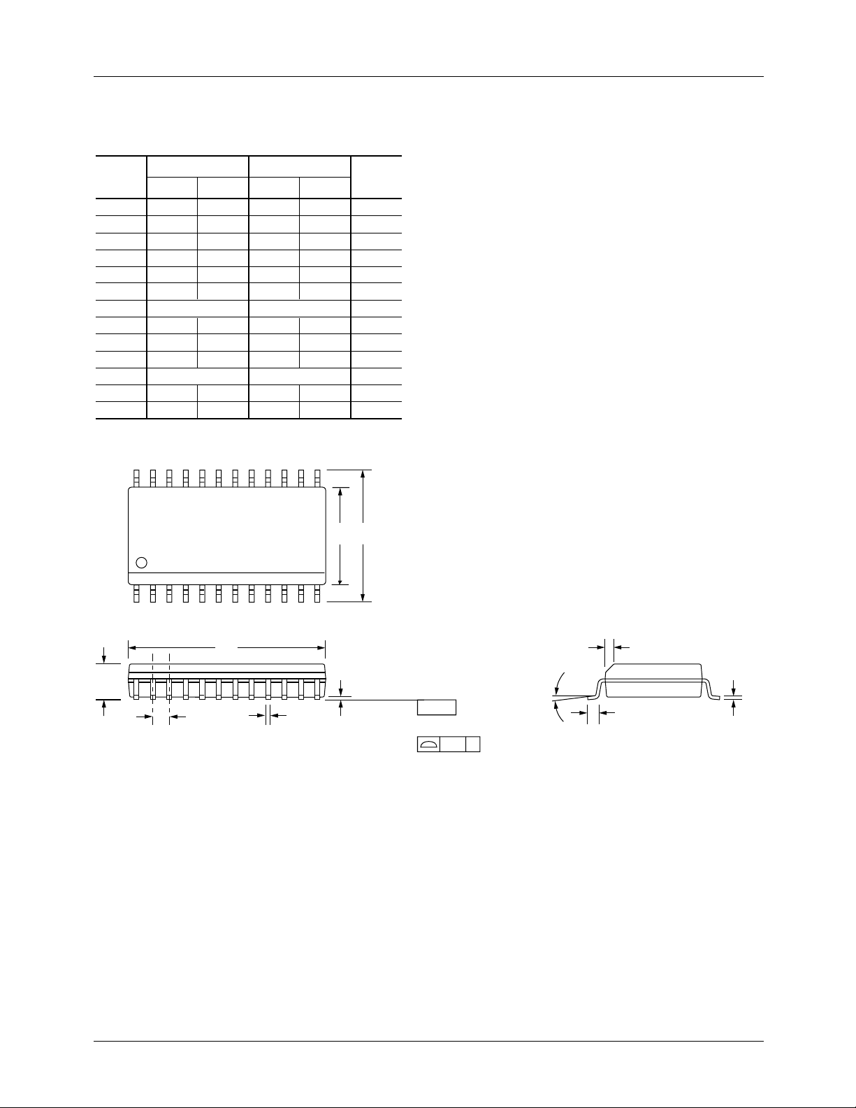
Mechanical Dimensions
24 Lead SOIC
Symbol
A .093 .104 2.35 2.65
A1 .004 .012 0.10 0.30
B .013 0.33
C .009 .013 0.23 0.32
D .599 .614 15.20 15.60
E .290 .299 7.36 7.60
e
H
h
L .016 .050 0.40 1.27
N24 24
α
ccc .004 0.10——
24 13
Inches
Min. Max. Min. Max.
.020 0.51
.050 BSC 1.27 BSC
.394 .419 10.00 10.65
.010 .020 0.25 0.51
0° 8° 0° 8°
Millimeters
Notes
5
2
2
3
6
H
E
Notes:
1.
Dimensioning and tolerancing per ANSI Y14.5M-1982.
2.
"D" and "E" do not include mold flash. Mold flash or
protrusions shall not exceed .010 inch (0.25mm).
3.
"L" is the length of terminal for soldering to a substrate.
4.
Terminal numbers are shown for reference only.
5.
"C" dimension does not include solder finish thickness.
6.
Symbol "N" is the maximum number of terminals.
112
D
A
e
B
A1
SEATING
PLANE
– C –
LEAD COPLANARITY
ccc C
h x 45°
C
α
L
REV. 1.0.0 6/30/00 17
Page 18

RC5058 PRODUCT SPECIFICATION
Ordering Information
Product Number Package
RC5058M 24 pin SOIC
DISCLAIMER
FAIRCHILD SEMICONDUCTOR RESERVES THE RIGHT TO MAKE CHANGES WITHOUT FURTHER NOTICE TO ANY
PRODUCTS HEREIN TO IMPROVE RELIABILITY, FUNCTION OR DESIGN. FAIRCHILD DOES NOT ASSUME ANY
LIABILITY ARISING OUT OF THE APPLICATION OR USE OF ANY PRODUCT OR CIRCUIT DESCRIBED HEREIN; NEITHER
DOES IT CONVEY ANY LICENSE UNDER ITS PATENT RIGHTS, NOR THE RIGHTS OF OTHERS.
LIFE SUPPORT POLICY
FAIRCHILD’S PRODUCTS ARE NOT AUTHORIZED FOR USE AS CRITICAL COMPONENTS IN LIFE SUPPORT DEVICES
OR SYSTEMS WITHOUT THE EXPRESS WRITTEN APPROVAL OF THE PRESIDENT OF FAIRCHILD SEMICONDUCTOR
CORPORATION. As used herein:
1. Life support devices or systems are devices or systems
which, (a) are intended for surgical implant into the body,
or (b) support or sustain life, or (c) whose failure to perform
when properly used in accordance with instructions for use
provided in the labeling, can be reasonably expected to
result in significant injury to the user.
2. A critical component is any component of a life support
device or system whose failure to perform can be
reasonably expected to cause the failure of the life support
device or system, or to affect its safety or effectiveness.
www.fairchildsemi.com
6/30/00 0.0m 012
2000 Fairchild Semiconductor Corporation
Stock#DS30005058
 Loading...