

Page 1
SCHOTTKY DIODES
FEATURES
High current rectifier Schottky diode
*
Low voltage,low inductance
*
For power supply
*
MECHANICAL DATA
* Case: Molded plastic
* Epoxy: UL 94V-O rate flame retardant
* Lead: MIL-STD-202E method 208C guaranteed
* Mounting position: Any
* Weight: 0.004 grams
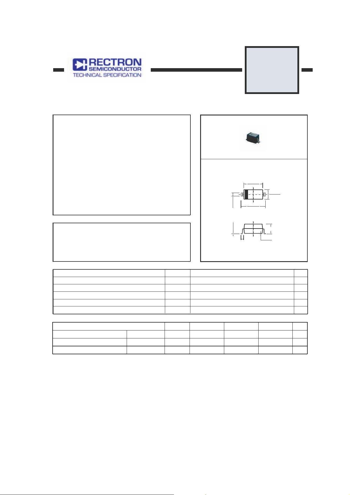
RB500V-40
.071(1.80)
.063(1.60)
.106(2.70)
.014(.35)
.010(.25)
.098(2.50)
.055(1.40)
.047(1.20)
SOD-323
MAXIMUM RATINGS AND ELECTRICAL CHARACTERISTICS
Single phase, half wave, 60 Hz, resistive or inductive load.
For capacitive load, derate current by 20%.
MAXIMUM RATINGS (@TA=25OC unless otherwise noted)
Maximum Peak reverse voltage
Maximum DC reverse voltage
Maximum Peak Forward Surge Current
Mean rectifying current
Operating and Storage Temperature Range
ELECTRICAL CHARACTERISTICS ( @ TA = 25oC unless otherwise noted )
Reverse voltage leakage current
Forward voltage
Diode Capacitance
Note: "Fully ROHS Compliant", "100% Sn plating (Pb-free)".
Ratings at 25OC ambient temperature unless otherwise specified.
RATINGS
SYMBOL RB500V-40
TJ,T
CHARACTERISTICS SYMBOL UNITS
(VR=10V)
(IF=10mA)
(VR=10V,f=1MHz)
V
I
V
FSM
I
I
V
C
.006(.15)
.003(.08)
REF .019(0.46)
MAX.039(1.00)
.004(.10)
.000(.00)
Dimensions in inches and (millimeters)
UNITS
RM
R
45
40
1
O
STG
MIN.
R
F
T
-
-
-
0.1
-40 to + 125
TYP.
-
-
6
MAX.
1
0.45
-
Volts
Volts
Amps
Amps
O
C
mA
V
pF
VC 2007-4
Page 2
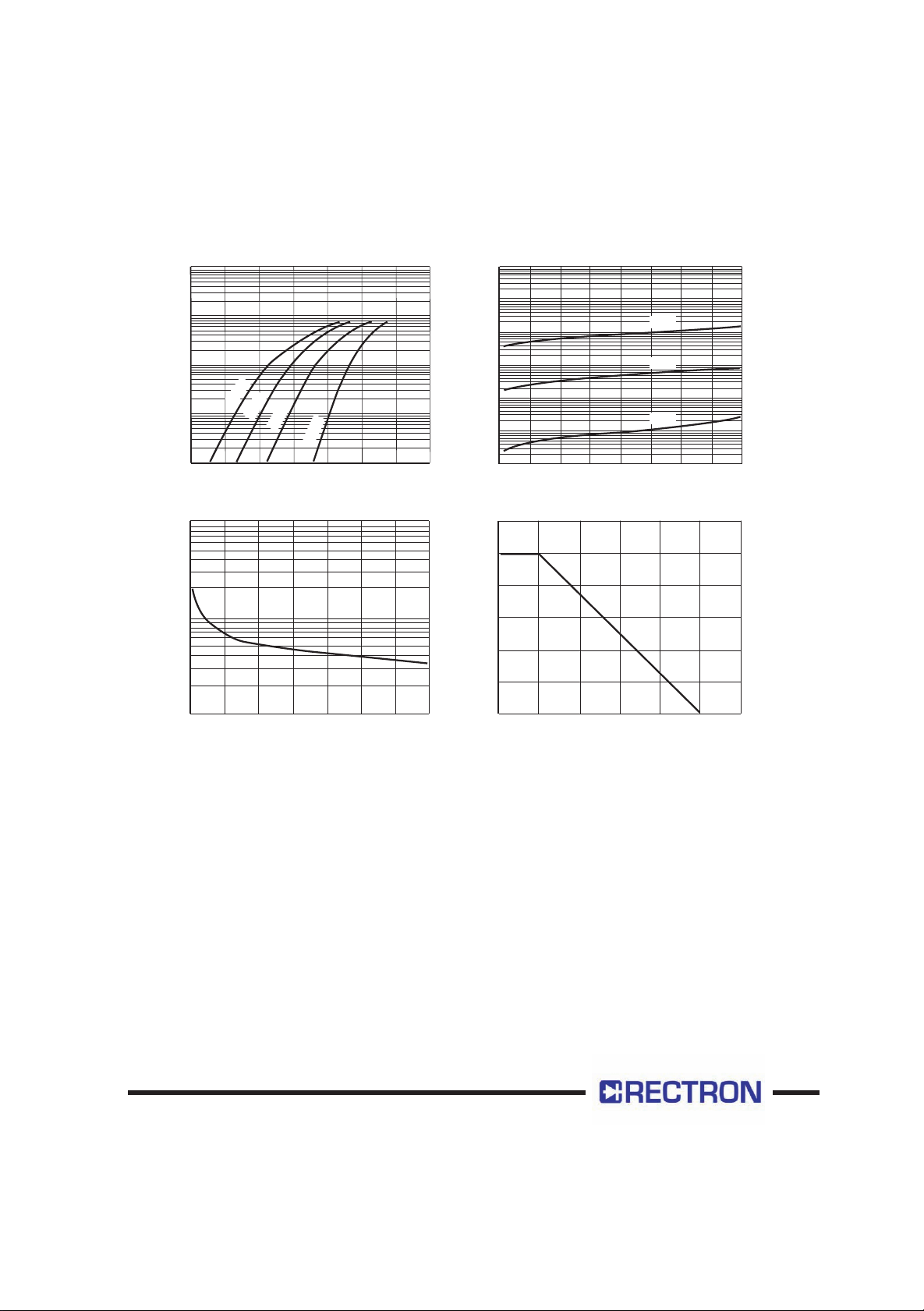
RATING AND CHARACTERISTICS CURVES ( RB500V-40 )
1000
100
10
O
C
125
C
O
. FORWARD CURRENT (mA)C
1
F
I
0.1
0
0.1
C
O
75
0.2
VF. FORWARD VOLTAGE (V)
25
0.3 0.4
C
O
-25
0.6 0.70.5
Figure1 Forward characteristics
100
10
. CAPACITANCE BETWEEN TERNINALS (pF)
T
1
0
10 15 20
5
VR.REVERSE VOLTAGE (V)
25 30 35
Figure3 Capacitance between terminals characteristics
10000
1000
100
10
125OC
75OC
1
. REVERSE CURRENT (mA)
R
I
0.1
0.01
0
10
VR. REVERSE VOLTAGE(V)
25OC
20
30
40
Figure2 Reverse characteristics
100
80
60
CURRENT (mA)
O.
40
I
20
0
0
TA.AMBIENT TEMPERATURE(OC)
100
75
1255025
Figure4 Derating curve(mounting on glass epoxy PCBs)
Page 3

DISCLAIMER NOTICE
Rectron Inc reserves the right to make changes without notice to any product
specification herein, to make corrections, modifications, enhancements or other
changes. Rectron Inc or anyone on its behalf assumes no responsibility or liabi lity for any errors or inaccuracies. Data sheet specifications and its information
contained are intended to provide a product description only. "Typical" paramet ers which may be included on RECTRON data sheets and/ or specifications ca n and do vary in different applications and actual performance may vary over ti me. Rectron Inc does not assume any liability arising out of the application or
use of any product or circuit.
Rectron products are not designed, intended or authorized for use in medical,
life-saving implant or other applications intended for life-sustaining or other rela ted applications where a failure or malfunction of component or circuitry may di rectly or indirectly cause injury or threaten a life without expressed written appr oval of Rectron Inc. Customers using or selling Rectron components for use in
such applications do so at their own risk and shall agree to fully indemnify Rect ron Inc and its subsidiaries harmless against all claims, damages and expendit ures.
Page 4

 Loading...