

Page 1
ELECTROSTATIC SENSITIVE DEVICE
OBSERVE HANDLING PRECAUTIONS
MITSUBISHI RF MOSFET MODULE
RA08H1317M
RoHS Compliance , 135-175MHz
8W
DESCRIPTION
The RA08H1317M is a 8-watt RF MOSFET Amplifier Module
for 12.5-volt portable radios that operate in the 135- to 175-MHz
range.
The battery can be connected directly to the drain of the
enhancement-mode MOSFET transistors. Without the gate
voltage (V
=0V), only a small leakage current flows into the
GG
drain and the RF input signal attenuates up to 60 dB. The output
power and drain current increase as the gate voltage increases.
With a gate voltage around 2.5V (minimum), output power and
drain current increases substantially. The nominal output power
becomes available at 3V (typical) and 3.5V (maximum). At
=3.5V, the typical gate current is 1 mA.
V
GG
This module is designed for non-linear FM modulation, but may
also be used for linear modulation by setting the drain quiescent
current with the gate voltage and controlling the output power
with the input power.
FEATURES
• Enhancement-Mode MOSFET Transistors
(I
≅0 @ VDD=12.5V, VGG=0V)
DD
• P
>8W @ VDD=12.5V, VGG=3.5V, Pin=20mW
out
• η
>40% @ P
T
=8W (VGG control), VDD=12.5V, Pin=20mW
out
• Broadband Frequency Range: 135-175MHz
• Low-Power Control Current I
=1mA (typ) at VGG=3.5V
GG
• Module Size: 30 x 10 x 5.4 mm
• Linear operation is possible by setting the quiescent drain
current with the gate voltage and controlling the output power
with the input power
12.5V, 2 stage Amp. For PORTABLE RADIO
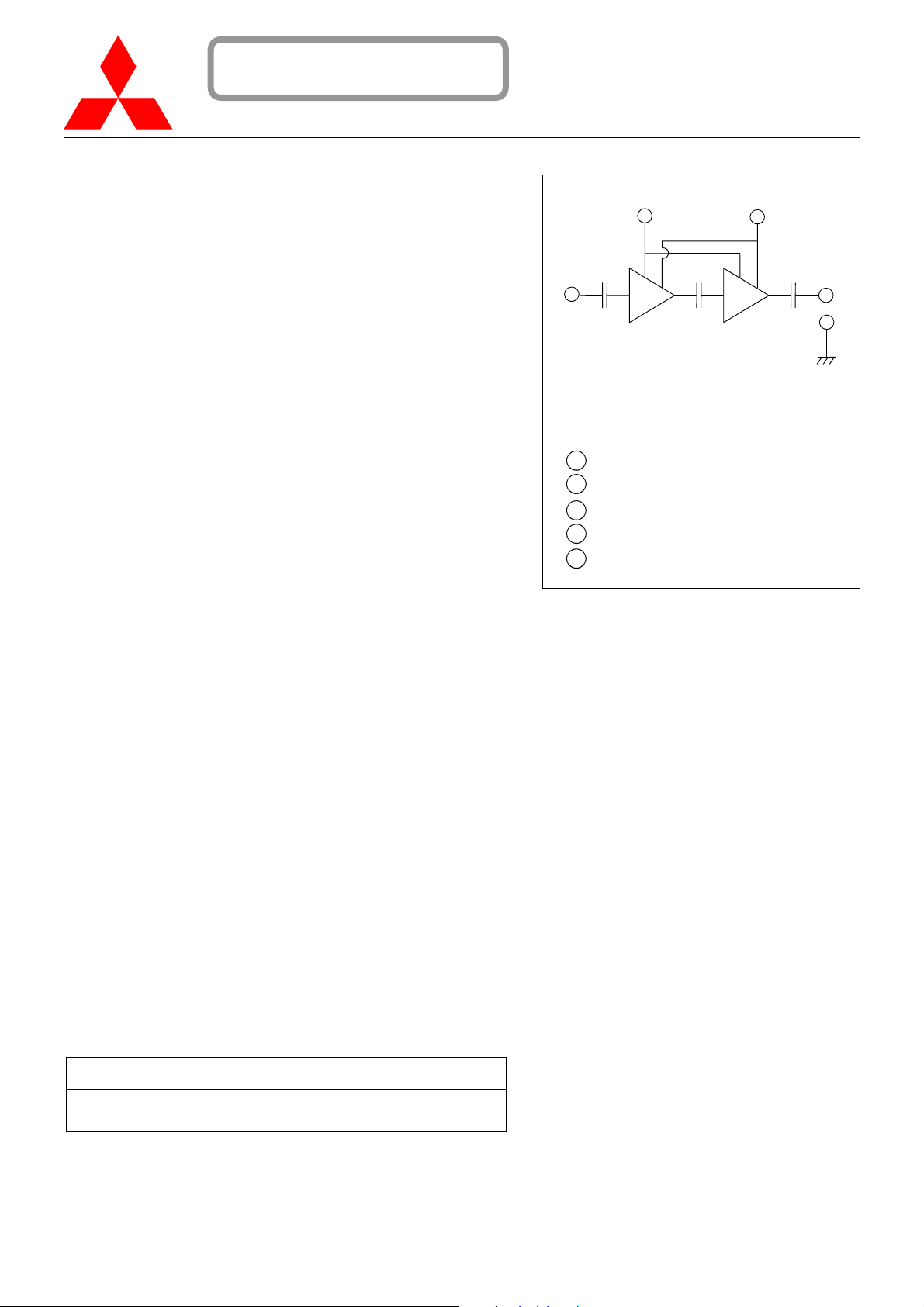
BLOCK DIAGRAM
2
1
1 RF Input (Pin)
2 Gate Voltage (V
3 Drain Voltage (V
4 RF Output (P
5 RF Ground (Case)
out
)
GG
DD
3
4
5
), Power Control
), Battery
PACKAGE CODE: H46S
RoHS COMPLIANCE
• RA08H1317M-101 is a RoHS compliant products.
• RoHS compliance is indicate by the letter “G” after the Lot Marking.
• This product include the lead in the Glass of electronic parts and the
lead in electronic Ceramic parts.
How ever,it applicable to the following exceptions of RoHS Directions.
1.Lead in the Glass of a cathode-ray tube, electronic parts, and
fluorescent tubes.
2.Lead in electronic Ceramic parts.
ORDERING INFORMATION:
ORDER NUMBER SUPPLY FORM
RA08H1317M-101
Antistatic tray,
25 modules/tray
RA08H1317M
MITSUBISHI ELECTRIC
1/8
24 Jan 2006
Page 2
MITSUBISHI RF POWER MODULE
RA08H1317M
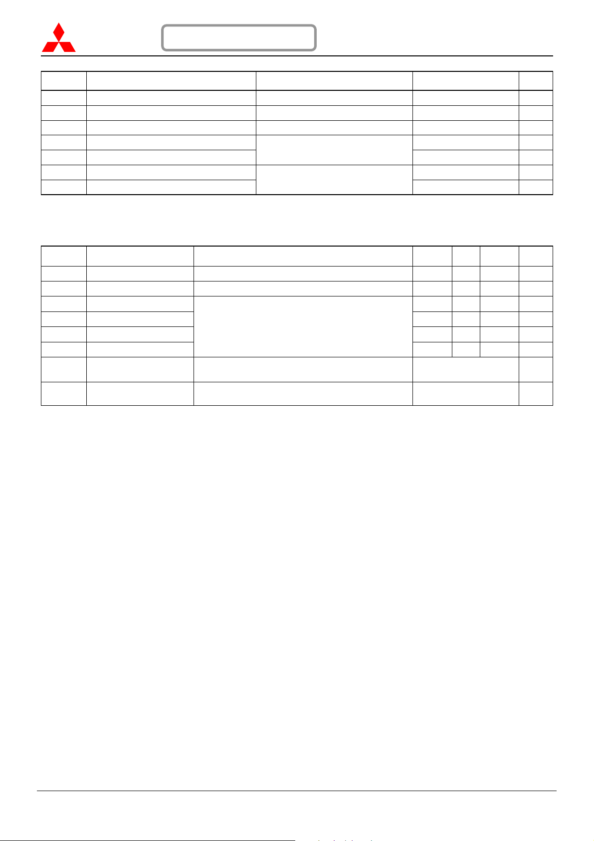
MAXIMUM RATINGS
ELECTROSTATIC SENSITIVE DEVICE
OBSERVE HANDLING PRECAUTIONS
(T
=+25°C, unless otherwise specified)
case
RoHS COMPLIANCE
SYMBOL PARAMETER CONDITIONS RATING UNIT
V
V
V
P
P
T
case(OP)
T
Drain Voltage VGG=0V, Pin=0W 16 V
DD
Drain Voltage VGG<3.5V 13.2 V
DD
Gate Voltage VDD<12.5V, Pin<20mW 4 V
GG
Input Power 40 mW
in
Output Power
out
Operation Case Temperature Range -30 to +90 °C
Storage Temperature Range
stg
f=135-175MHz,
Z
=50Ω
G=ZL
10 W
-40 to +110 °C
The above parameters are independently guaranteed.
ELECTRICAL CHARACTERISTICS
(T
=+25°C, ZG=ZL=50Ω, unless otherwise specified)
case
SYMBOL PARAMETER CONDITIONS MIN TYP MAX UNIT
f Frequency Range 135 175 MHz
P
η
2f
ρ
I
GG
— Stability
— Load VSWR Tolerance
Output Power
out
Total Efficiency 40 %
T
2nd Harmonic -25 dBc
o
Input VSWR 4.4:1 —
in
V
=12.5V,VGG=3.5V, Pin=20mW
DD
P
=8W (VGG control),
out
=12.5V,
V
DD
=20mW
P
in
Gate Current
=5-13.2V, Pin=10-30mW, P
V
DD
<9W (VGG control),
out
Load VSWR=4:1
V
=13.2V, Pin=20mW, P
DD
=8W (VGG control),
out
Load VSWR=20:1
8 W
1 mA
No parasitic oscillation —
No degradation or destroy —
All parameters, conditions, ratings, and limits are subject to change without notice.
RA08H1317M
MITSUBISHI ELECTRIC
2/8
24 Jan 2006
Page 3
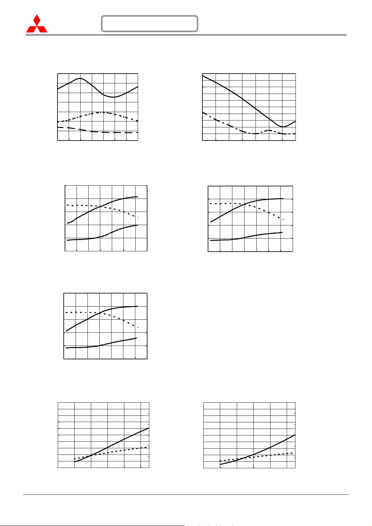
TYPICAL PERFORMANCE
OUTPUT POWE R, TOTAL EFFICIENCY, 2nd, 3rd HARMONICS versus FREQUENCY
and INPUT VSWR versus FREQUENCY
14
12
(W)
out
(-)
in
10
ρ
8
6
4
INPUT VSWR
2
OUTPUT POWER P
0
120 130 140 150 160 170 180 190
@VGG=3.5V
P
out
@P
=8W
η
out
T
ρ
@P
=8W
in
out
FREQUENCY f(MHz)
OUTPUT POWER, POWER GAIN and OUTPUT POWER, POWER GAIN and
DRAIN CURRENT versus INPUT POWER DRAIN CURRENT versus INPUT POWER
50
40
30
(dBm)
out
20
P
OUTPUT POWER
10
POWER GAIN Gp(dB)
0
Gp
I
DD
-15 -10 -5 0 5 10 15 20
INPUT POWER P
OUTPUT POWER, POWER GAIN and
DRAIN CURRENT versus INPUT POWER
50
40
30
(dBm)
out
20
P
OUTPUT POWER
10
POWER GAIN Gp(dB)
0
Gp
-15 -10 -5 0 5 10 15 20
INPUT POWER P
ELECTROSTATIC SENSITIVE DEVICE
OBSERVE HANDLING PRECAUTIONS
(T
=+25°C, ZG=ZL=50Ω, unless otherwise specified)
case
140
120
-20
-30
100
VDD=12.5V
=20mW
P
in
80
60
40
(%)
T
η
20
TOTAL EFFICIENCY
0
HARMONICS (dBc)
-40
-50
-60
-70
120 130 140 150 160 170 180 190
f=135MHz,
V
V
(dBm)
in
P
out
=12.5V,
DD
=3.5V
GG
5
(A)
4
DD
3
2
1
DRAIN CURRENT I
0
50
40
30
(dBm)
out
20
P
OUTPUT POWER
10
POWER GAIN Gp(dB)
0
5
P
out
(A)
4
DD
3
2
I
DD
(dBm)
in
f=175MHz,
V
=12.5V,
DD
V
=3.5V
GG
1
DRAIN CURRENT I
0
MITSUBISHI RF POWER MODULE
RoHS COMPLIANCE
VDD=12.5V
=3.5V
V
GG
=20mW
P
in
rd
@P
=8W
3
out
RA08H1317M
nd
2
@P
=8W
out
FREQUENCY f(MHz)
Gp
I
DD
P
out
f=155MHz,
=12.5V,
V
DD
=3.5V
V
GG
-15 -10 -5 0 5 10 15 20
INPUT POWER P
(dBm)
in
5
(A)
4
DD
I
3
2
1
DRAIN CURRENT
0
OUTPUT POWER and DRAIN CURRENT OUTPUT POWER and DRAIN CURRENT
20
18
(W)
16
out
14
12
10
8
6
4
2
OUTPUT POWER P
0
RA08H1317M
versus DRAIN VOLTAGE versus DRAIN VOLTAGE
f=135MHz,
=3.5V,
V
GG
P
=20mW
in
P
out
I
DD
2 4 6 8 10 12
DRAIN VOLTAGE V
(V)
DD
(W)
out
OUTPUT POWER P
20
18
16
14
12
10
8
6
4
2
0
f=155MHz,
V
=3.5V,
GG
P
=20mW
in
6
5
4
3
2
1
0
(A)
DD
DRAIN CURRENT I
24681012
MITSUBISHI ELECTRIC
3/8
DRAIN VOLTAGE V
6
5
(A)
DD
4
P
out
3
2
I
DD
(V)
DD
1
DRAIN CURRENT I
0
24 Jan 2006
Page 4
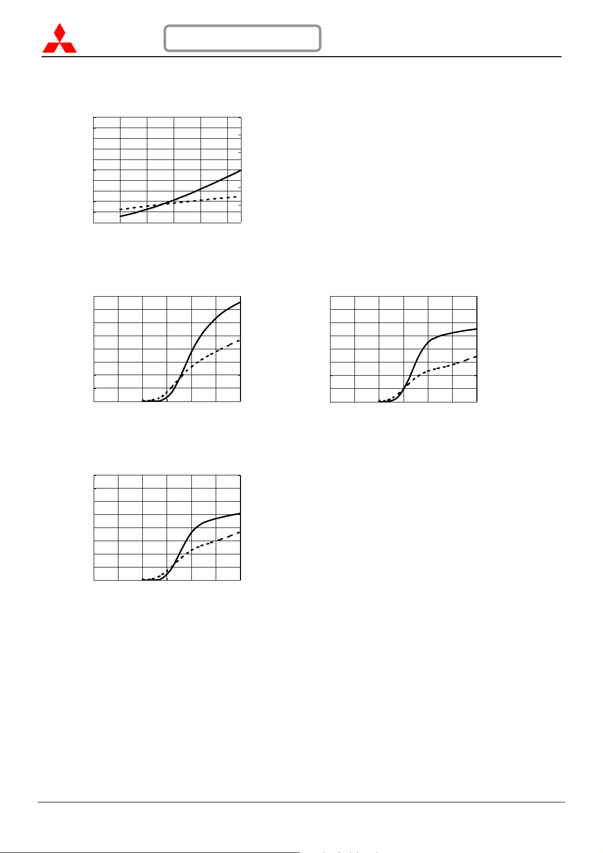
TYPICAL PERFORMANCE
OUTPUT POWER and DRAIN CURRENT
20
18
(W)
16
out
14
12
10
8
6
4
2
OUTPUT POWER P
0
24681012
OUTPUT POWER and DRAIN CURRENT OUTPUT POW ER and DRAIN CURRENT
16
14
(W)
out
12
10
8
6
4
2
OUTPUT POWER P
0
11.522.533.54
versus DRAIN VOLTAGE
f=175MHz,
=3.5V,
V
GG
P
=20mW
in
DRAIN VOLTAGE V
versus GATE VOLTAGE versus GATE VOLTAGE
f=135MHz,
=12.5V,
V
DD
P
=20mW
in
GATE VOLTAGE V
ELECTROSTATIC SENSITIVE DEVICE
OBSERVE HANDLING PRECAUTIONS
(T
=+25°C, ZG=ZL=50Ω, unless otherwise specified)
case
6
5
(A)
DD
4
3
P
out
I
DD
(V)
DD
P
out
2
1
DRAIN CURRENT I
0
4
(A)
3
DD
2
I
DD
1
DRAIN CURRENT I
0
16
14
(W)
out
12
10
8
6
4
2
OUTPUT POWER P
0
11.522.533.54
(V)
GG
RoHS COMPLIANCE
f=155MHz,
=12.5V,
V
DD
=20mW
P
in
GATE VOLTAGE V
GG
MITSUBISHI RF POWER MODULE
RA08H1317M
4
(A)
3
DD
2
I
DD
1
DRAIN CURRENT I
0
(V)
P
out
OUTPUT POWER and DRAIN CURRENT
versus GATE VOLTAGE
16
f=175MHz,
14
(W)
out
12
10
8
6
4
2
OUTPUT POWER P
0
=12.5V,
V
DD
P
in
=20mW
P
out
11.522.533.54
GATE VOLTAGE V
(V)
GG
4
(A)
3
DD
2
I
DD
1
DRAIN CURRENT I
0
RA08H1317M
MITSUBISHI ELECTRIC
4/8
24 Jan 2006
Page 5
ELECTROSTATIC SENSITIVE DEVICE
OBSERVE HANDLING PRECAUTIONS
MITSUBISHI RF POWER MODULE
RoHS COMPLIANCE
RA08H1317M
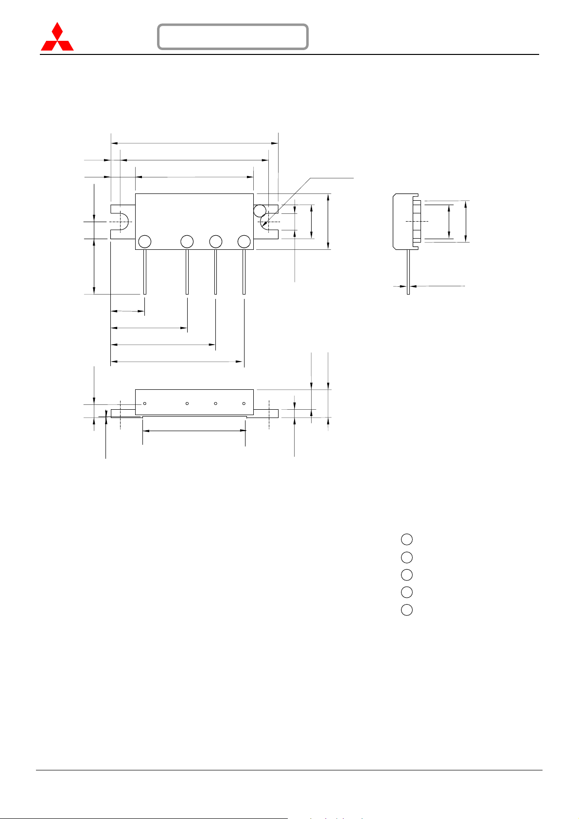
OUTLINE DRAWING
(1.7)
(4.4)
3.0 ±0.2
6.0 ±1 2.3 ±0.4
6.1 ±1
(mm)
1
13.7 ±1
18.8 ±1
23.9 ±1
30.0 ±0.2
26.6 ±0.2
21.2 ±0.2
2
2-R1.5 ±0.1
5
6.0 ±0.2
3.5 ±0.2
10.0 ±0.2
(5.4)
3
4
3.0 ±0.2
6.0 ±0.2
Ø0.45 ±0.15
7.4 ±0.2
(19.2)
0.05 +0.04/-0
1.5 ±0.2
1 RF Input (P
)
in
2 Gate Voltage (V
3 Drain Voltage (V
4 RF Output (P
out
)
GG
)
DD
)
5 RF Ground (Case)
RA08H1317M
MITSUBISHI ELECTRIC
5/8
24 Jan 2006
Page 6
Ω
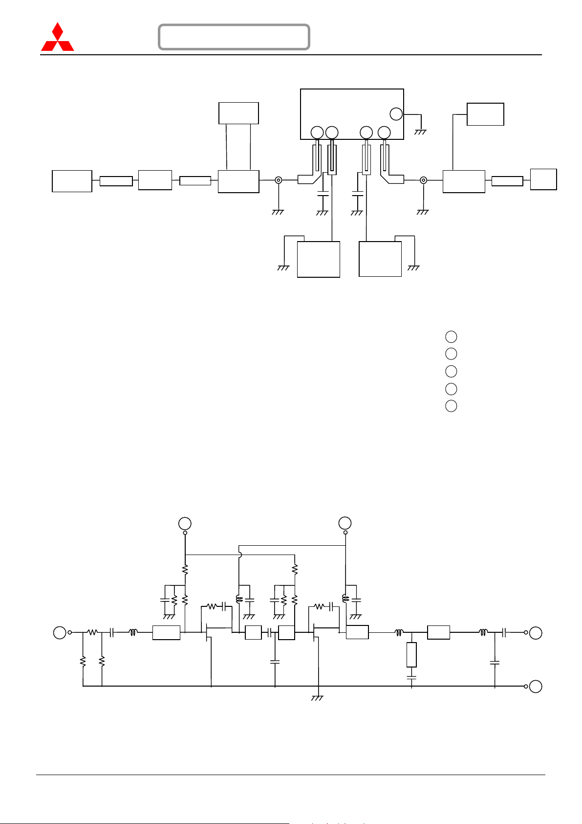
TEST BLOCK DIAGRAM
Generator
Signal
Attenuator
amplifier
C1, C2: 4700pF, 22uF in parallel
EQUIVALENT CIRCUIT
1
ELECTROSTATIC SENSITIVE DEVICE
OBSERVE HANDLING PRECAUTIONS
Power
Meter
Pre-
Attenuator
Directional
Coupler
2
ZG=50
1
C1 C2
- +
DC Power
Supply V
RoHS COMPLIANCE
2
GG
DUT
3
DC Power
Supply V
4
+ -
5
Z
DD
=50Ω
3
MITSUBISHI RF POWER MODULE
RA08H1317M
Spectrum
Analyzer
Directional
Coupler
Attenuator
1 RF Input (P
2 Gate Voltage (V
3 Drain Voltage (V
4 RF Output (P
5 RF Ground (Case)
Power
Meter
)
in
GG
DD
)
out
4
5
)
)
RA08H1317M
MITSUBISHI ELECTRIC
24 Jan 2006
6/8
Page 7
ELECTROSTATIC SENSITIVE DEVICE
OBSERVE HANDLING PRECAUTIONS
RoHS COMPLIANCE
MITSUBISHI RF POWER MODULE
RA08H1317M
PRECAUTIONS, RECOMMENDATIONS, and APPLICATION INFORMATION:
Construction:
This module consists of an alumina substrate soldered onto a copper flange. For mechanical protection, a plastic
cap is attached with silicone. The MOSFET transistor chips are die bonded onto metal, wire bonded to the
substrate, and coated with resin. Lines on the substrate (eventually inductors), chip capacitors, and resistors form
the bias and matching circuits. Wire leads soldered onto the alumina substrate provide the DC and RF connection.
Following conditions must be avoided:
a) Bending forces on the alumina substrate (for example, by driving screws or from fast thermal changes)
b) Mechanical stress on the wire leads (for example, by first soldering then driving screws or by thermal expansion)
c) Defluxing solvents reacting with the resin coating on the MOSFET chips (for example, Trichlorethylene)
d) Frequent on/off switching that causes thermal expansion of the resin
e) ESD, surge, overvoltage in combination with load VSWR, and oscillation
ESD:
This MOSFET module is sensitive to ESD voltages down to 1000V. Appropriate ESD precautions are required.
Mounting:
Heat sink flatness must be less than 50 µm (a heat sink that is not flat or particles between module and heat sink
may cause the ceramic substrate in the module to crack by bending forces, either immediately when driving screws
or later when thermal expansion forces are added).
A thermal compound between module and heat sink is recommended for low thermal contact resistance and to
reduce the bending stress on the ceramic substrate caused by the temperature difference to the heat sink.
The module must first be screwed to the heat sink, then the leads can be soldered to the printed circuit board.
M3 screws are recommended with a tightening torque of 0.4 to 0.6 Nm.
Soldering and Defluxing:
This module is designed for manual soldering.
The lead (terminal) must be soldered after the module is screwed onto the heat sink.
The temperature of the lead (terminal) soldering should be lower than 350°C and shorter than 3 second.
Ethyl Alcohol is recommend for removing flux. Trichloroethylene solvents must not be used (they may cause
bubbles in the coating of the transistor chips which can lift off the bond wires).
Thermal Design of the Heat Sink:
=8W, VDD=12.5V and Pin=20mW each stage transistor operating conditions are:
At P
out
Stage
st
1
nd
2
P
in
(W)
P
out
(W)
R
th(ch-case)
(°C/W)
0.02 1.5 4.0 0.3
1.5 8.0 2.4 1.32
I
@ η
DD
(A)
The channel temperatures of each stage transistor Tch = T
T
= T
ch1
= T
T
ch2
+ (12.5V x 0.3A – 1.5W + 0.02W) x 4.0°C/W = T
case
+ (12.5V x 1.32A – 8.0W + 1.5W) x 2.4°C/W = T
case
=40%
T
+ (VDD x IDD - P
case
V
DD
(V)
12.5
+ 9.1 °C
case
+ 24.0 °C
case
+ Pin) x R
out
th(ch-case)
are:
For long-term reliability, it is best to keep the module case temperature (T
temperature T
+ P
) of the heat sink, including the contact resistance, is:
in
R
th(case-air)
=60°C and P
air
=8W, the required thermal resistance R
out
= (90°C - 60°C) / (8W/40% – 8W + 0.02W) = 2.50 °C/W
th (case-air)
) below 90°C. For an ambient
case
= ( T
case
- T
) / ( (P
air
/ ηT ) - P
out
When mounting the module with the thermal resistance of 2.50 °C/W, the channel temperature of each stage
transistor is:
= T
= T
+ 39.1 °C
air
+ 54.0 °C
air
T
ch1
T
ch2
The 175°C maximum rating for the channel temperature ensures application under derated conditions.
out
RA08H1317M
MITSUBISHI ELECTRIC
7/8
24 Jan 2006
Page 8
ELECTROSTATIC SENSITIVE DEVICE
y
r
OBSERVE HANDLING PRECAUTIONS
RoHS COMPLIANCE
MITSUBISHI RF POWER MODULE
RA08H1317M
Output Power Control:
Depending on linearity, the following two methods are recommended to control the output power:
a) Non-linear FM modulation:
By the gate voltage (V
GG
).
When the gate voltage is close to zero, the RF input signal is attenuated up to 60 dB and only a small leakage
current flows from the battery into the drain.
Around V
Around V
=2.5V, the output power and drain current increases substantially.
GG
=3V (typical) to VGG=3.5V (maximum), the nominal output power becomes available.
GG
b) Linear AM modulation:
By RF input power P
.
in
The gate voltage is used to set the drain’s quiescent current for the required linearity.
Oscillation:
To test RF characteristics, this module is put on a fixture with two bias decoupling capacitors each on gate and
drain, a 4.700 pF chip capacitor, located close to the module, and a 22 µF (or more) electrolytic capacitor.
When an amplifier circuit around this module shows oscillation, the following may be checked:
a) Do the bias decoupling capacitors have a low inductance pass to the case of the module?
b) Is the load impedance Z
c) Is the source impedance Z
=50Ω?
L
=50Ω?
G
Frequent on/off switching:
In base stations, frequent on/off switching can cause thermal expansion of the resin that coats the transistor chips
and can result in reduced or no output power. The bond wires in the resin will break after long-term thermally
induced mechanical stress.
Quality:
Mitsubishi Electric is not liable for failures resulting from base station operation time or operating conditions
exceeding those of mobile radios.
This module technology results from more than 20 years of experience, field proven in tens of millions of mobile
radios. Currently, most returned modules show failures such as ESD, substrate crack, and transistor burnout,
which are caused by improper handling or exceeding recommended operating conditions. Few degradation failures
are found.
Keep safety first in your circuit designs!
Mitsubishi Electric Corporation puts the maximum effort into making semiconductor products better and more reliable, but there
is always the possibility that trouble may occur. Trouble with semiconductors may lead to personal injury, fire or propert
damage. Remember to give due consideration to safety when making your circuit designs, w ith appropriate measures such as
(i) placement of substitutive, auxiliary circuits, (ii) use of non-flammable material, or (iii) prevention against any malfunction o
mishap.
RA08H1317M
MITSUBISHI ELECTRIC
24 Jan 2006
8/8
 Loading...