

Page 1
Powerex, Inc., 200 Hillis Street, Youngwood, Pennsylvania 15697-1800 (724) 925 7272
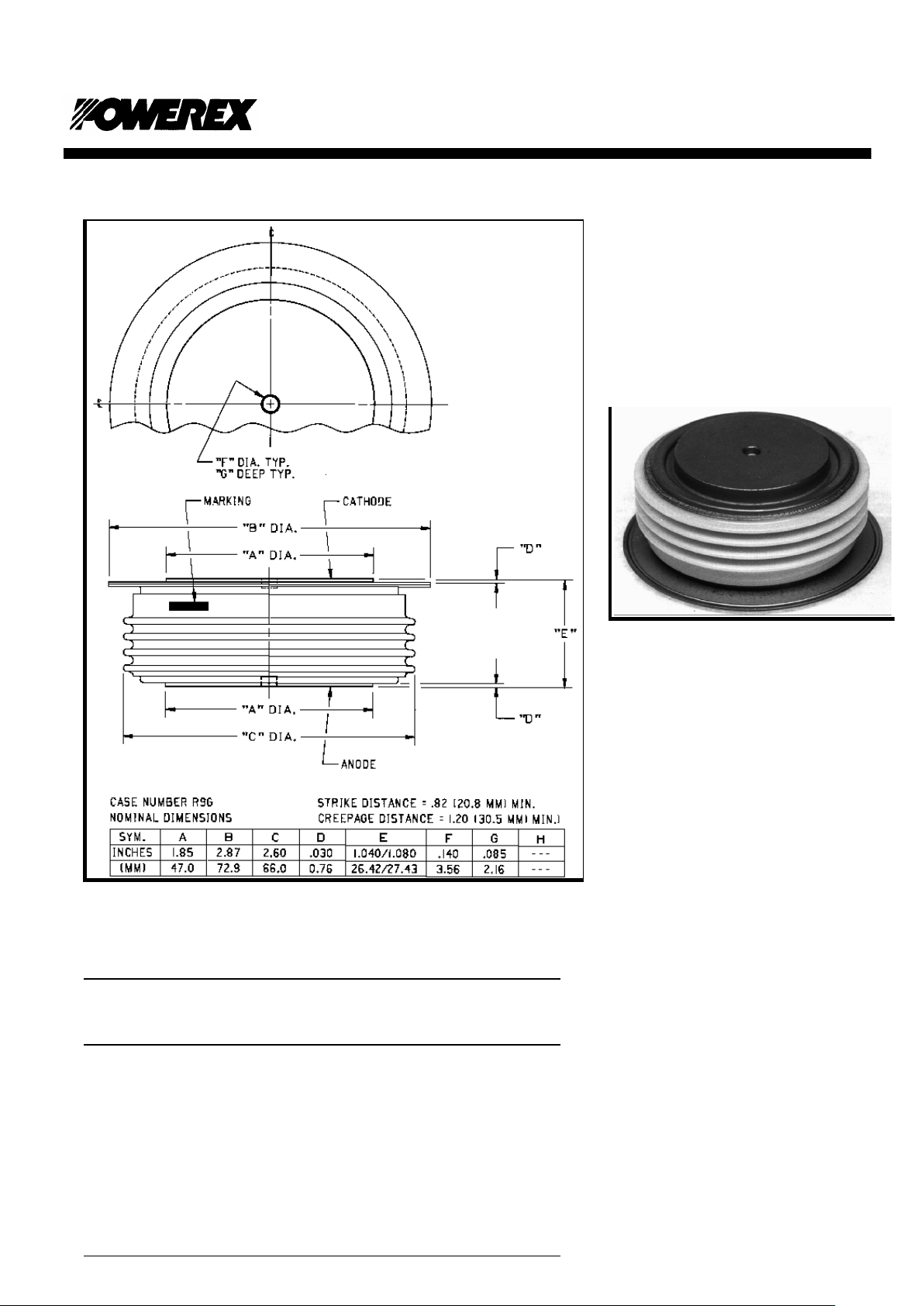
Rectifier Diode
1800 Amperes/Up to 3200 Volts
Ordering Information
Select the complete 10 digit device part number from the table below.
Description:
Powerex General Purpose Rectifiers are
designed with high blocking voltage capability
with low forward on-state voltage to minimize
conduction losses. These are all-diffused,
hermetic Pow-R-Disc devices which can be
mounted using commercially available clamps
and heatsinks..
Features:
n
Low On-State Voltage
n
Low Thermal Impedance
n
Hermetic Packaging
n
Excellent Surge and I2t Ratings
Applications:
n
Power Supplies
n
Motor Control
n
Free Wheeling Diode
R9G0
1800A
Type Voltage
V
RRM
Current
I
T(av)
Recovery
Time
trr
R9G0
12
through
32
16 XX
1200 V
through
3200 V
1600 A 25 µs
typical
11-09-1999
Page 2

Powerex, Inc., Hillis Street, Youngwood, Pennsylvania 15697-1800 (724) 925 7272
R9G0
Rectifier Diode
1800 Amperes / Up to 3200 Volts
Absolute Maximum Ratings
Conditions Symbol Units
Repetitive Peak Reverse Blocking Voltage V
RRM
up to 3200 V
Non-Repetitive Peak Reverse Blocking Voltage V
RSM
V
RRM
+ 100 V
RMS Forward Current I
F(RMS)
2825 A
Average Forward Current 180° Conduction, TC=110°C I
F(AV)
1800 A
Peak Half Cycle Non-Repetitive Surge Current t = 8.3mS, 100%V
RRM
reapplied I
FSM
21,500 A
Peak Half Cycle Non-Repetitive Surge Current t = 10mS, 100%V
RRM
reapplied I
FSM
19,600 A
I2t for Fusing for One Cycle I2t 1.925x10⁶ A2-sec
I2t of Package t = 8.3mS I2t 90x106 A2-sec
Operating Junction Temperature TJ -40 to +175
°
C
Storage Temperature T
stg
-40 to +190
°
C
Mounting Force - - - - 5000 to 6000
2270 to 2700
lb.
kg
Module Weight, Typical - - - - 454
1.0
g
lbs
R9G0
1800A
11-09-1999
Page 3

Powerex, Inc., Hillis Street, Youngwood, Pennsylvania 15697-1800 (724) 925 7272
R9G0
Rectifier Diode
1800 Amperes / Up to 3200 Volts
Electrical and Thermal Characteristics, TJ=25°C unless otherwise specified
Characteristics Symbol Test Conditions Min. Typ. Max Units
Peak Reverse Leakage Current I
RRM
TJ=175°C, Rated V
RRM
150 mA
Peak On-State Voltage VFM TJ=25°C, IFM=1500A 1.20 V
Threshold Voltage, Low-level
Slope Resistance, Low-level
V
(TO)1
rT1
TJ = 175°C, I = 15%I
F(AV)
to pI
F(AV)
.814
.224
V
mO
Threshold Voltage, High-level
Slope Resistance, High-level
V
(TO)2
rT2
TJ = 175°C, I = pI
F(AV)
to I
FSM
1.03
.198
V
mO
VFM Coefficients, Full Range TJ = 175°C, I = 15%I
F(AV)
to I
FSM
VFM=A + B Ln (IFM)+ C IFM+ D v(IFM)
A = 2.06
B = -0.232
C = 0.000130
D = 0.0179
Maximum Reverse Recovery Current
I
R(Rec)
TJ = 175°C, di/dt = -1 A/µs
TJ = 175°C, di/dt = -10A/µs
70
250
A
A
Typical Reverse Recovery Time trr TC = 25°C, IFM = 1500 A
diR/dt = 25 A/µsec, tp = 190 µsec
25
µ
sec
Thermal Characteristics
Characteristics Symbol Min. Typ. Max. Units
Thermal Resistance, Junction to Case
R
T
JC
------
------ 0.02
°
C/W
Thermal Resistance, Case to Sink Lubricated
R
T
CS
------ ------ 0.0075
°
C/W
Maximum Transient Thermal Impedance
0
0.005
0.01
0.015
0.02
0.025
0.0001 0.001 0.01 0.1 1 10 100
Time - t - Seconds
Thermal Impedance - Zjc - °C/W
(Junction to Case)
Maximum On-State Forward Voltage Drop
0
1
2
3
4
5
10 100 1000 10000 100000
Instantaneous On-State Current - Ifm - Amperes
On-State Voltage - Vfm - Volts
( Tj = 175 °C )
R9G0
1800A
11-09-1999
Page 4

Powerex, Inc., Hillis Street, Youngwood, Pennsylvania 15697-1800 (724) 925 7272
Maximum On-State Power Dissipation
30°
90°
180°
0
500
1000
1500
2000
2500
3000
3500
0 200 400 600 800 1000 1200 1400 1600 1800 2000
Average On-State Current - If(av) - Amperes
Maximum Power Dissipation - Watts
(Sinusoidal Waveform)
Maximum Allowable Case Temperature
180°
90°
30°
100
110
120
130
140
150
160
170
180
0 200 400 600 800 1000 1200 1400 1600 1800 2000
Average On-State Current - If(av) - Amperes
Max. Case Temperature - Tcase - °C
(Sinusoidal Waveform)
Maximum On-State Power Dissipation
120°
60°
180°
360°
0
500
1000
1500
2000
2500
3000
3500
4000
4500
0 400 800 1200 1600 2000 2400 2800 3200
Average On-State Current - If(av) - Amperes
Maximum Power Dissipation - Watts
(Rectangular Waveform)
Maximum Allowable Case Temperature
360°
180°
120°
60°
90
100
110
120
130
140
150
160
170
180
0 500 1000 1500 2000 2500 3000
Average On-State Current If(av) Amperes
Max. Case Temperature Tcase °C
(Rectangular Waveform)
R9G0
1800A
11-09-1999
 Loading...