

Page 1
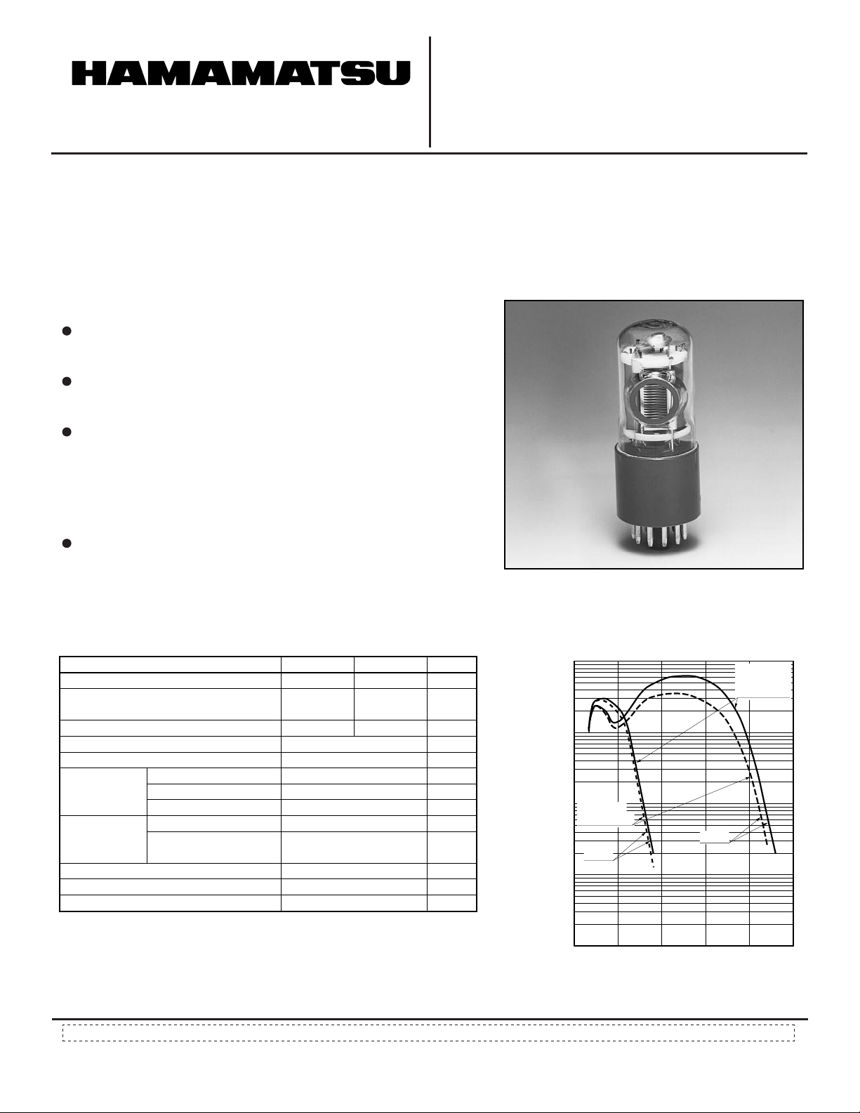
PHOTOMULTIPLIER TUBES
PRELIMINARY DATA
FEB. 2001
R8486, R8487
For Vacuum Ultraviolet Light Detection
Cs-Te (R8486), Cs-I (R8487) Photocathode, MgF
28 mm (1-1/8 Inch) Diameter, 9-stage, Side-on Type
FEATURES
Sensitivity in the Vacuum Ultraviolet Region
R8486.............................................................115 to 320 nm
R8487.............................................................115 to 195 nm
High Quantum Efficiency (at 121.6 nm)
R8486...............................................................22.5 % (Typ.)
R8487...............................................................26.0 % (Typ.)
High Anode Sensitivity
R8486 (at 254 nm)................................5.2 × 10
R8487 (at 121.6 nm).............................1.0 × 10
5
A/W (Typ.)
5
A/W (Typ.)
2 Window,
APPLICATIONS
Emission Spectroscopy, etc.
GENERAL
Parameter R8486 Unit
Spectral Response
Wavelength
of Maximum Response
Photocathode Material
Window Material
Minimum Effective Area
Structure
Dynode
Direct
Interelectrode
Capacitances
Base
Weight
Suitable Socket for Base (option)
Number of Stage
Material
Anode to Dynode No.9
Anode to
All Other Electrodes
R8487
115 to 320
200
Cs-Te
115 to 195
2
MgF
130
Cs-I
8 × 12
Circular-cage
9
Sb-Cs
Approx. 4
Approx. 6
11-pin base JEDEC No. B11-88
45
E678-11A
nm
nm
—
—
mm
—
—
—
pF
pF
—
g
—
Figure 1: Typical Spectral Response
TPMSB0199EA
100
10
1
QUANTUM
EFFICIENCY
R8486
R8487
QUANTUM EFFICIENCY (%)
0.1
PHOTOCATHODE RADIANT SENSITIVITY (mA/W)
0.01
100
200
PMSF0093
CATHODE
RADIANT
SENSITIVITY
300
WAVELENGTH (nm)
Subject to local technical requirements and regulat ions, availability of products included in this promotional material may var y. P lease consult with our sales office.
Information furnished by HAMA M ATSU is believed to be reliable. However, n o responsibility is assumed for possible inaccuracies or omissions. Specifications are
subject to change without notice. No patent rights are granted to any of the circuits described herein.
2001 Hamamatsu Photonics K.K.
©
Page 2
PHOTOMULTIPLIER TUBES R8486, R8487
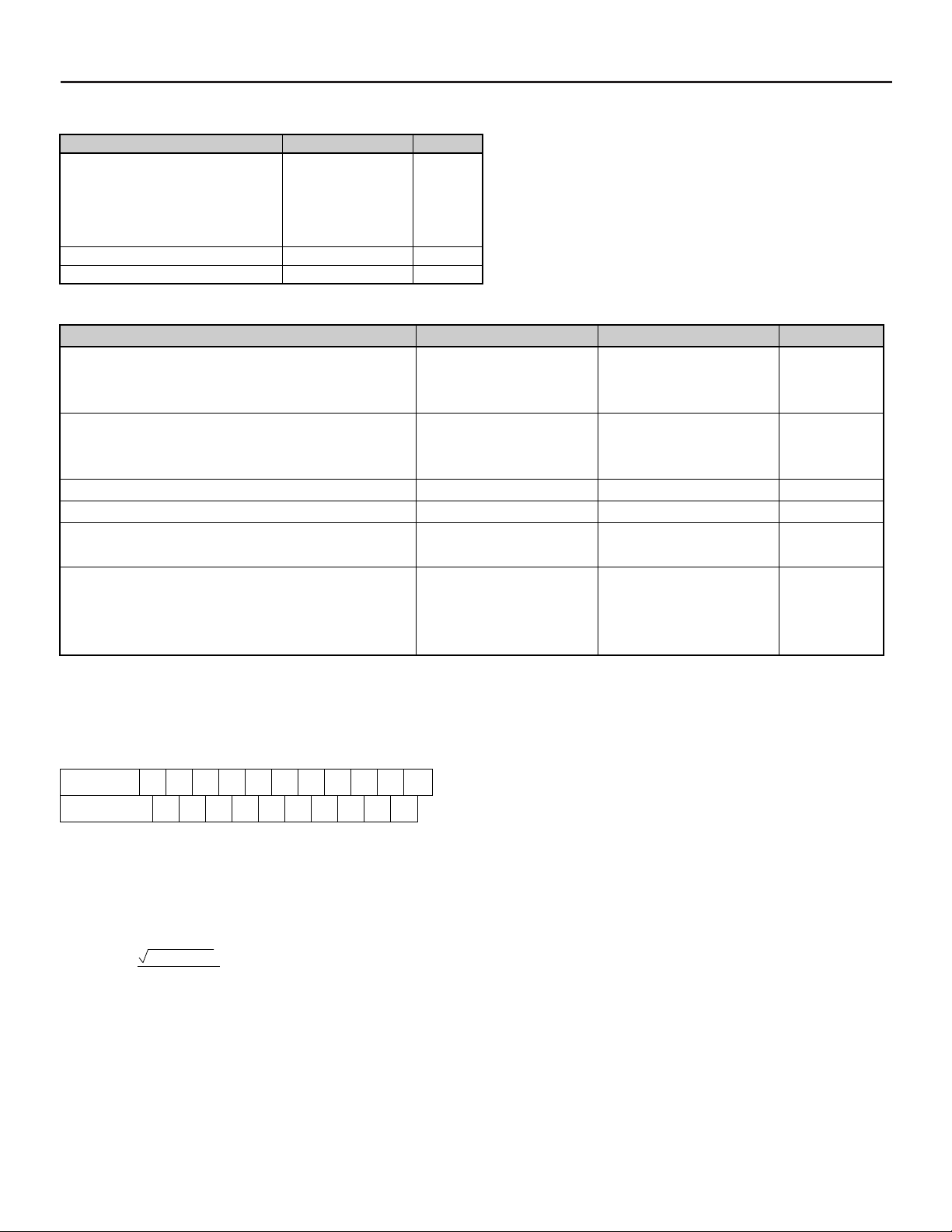
MAXIMUM RATINGS (Absolute Maximum Values)
Parameter
Supply Voltage
Between Anode and Cathode
Between Anode and Last Dynode
Between Successive Dynodes
Between First Dynode and Cathode
A
Average Anode Current
Ambient Temperature
CHARACTERISTICS (at 25 °C)
Parameter R8487R8486 Unit
Cathode Sensitivity
Quantum Efficiency at 121 nm
at 254 nm
Anode Sensitivity
Radiant at 121 nm
at 254 nm
Gain
Anode Dark Current (After 30 minute storage in darkness)
ENI (Equivalent Noise Input) D at 121 nm
at 254 nm
Time Response
Anode Pulse Rise Time
Electron Transit Time
Transit Time Spread
B
E
F
G
Rating Unit
1250
250
250
250
0.1
-30 to +50
C
V dc
V dc
V dc
V dc
V dc
°C
22.5
25.0
—
5.2 × 10
1.0 × 10
1.0
—
1.09 × 10
2.2
22
1.2
5
7
-16
26.0
—
1.0 × 10
—
3.9 × 10
0.1
1.12 × 10
—
2.2
22
1.2
5
6
-16
%
%
A/W
A/W
—
nA
W
W
ns
ns
ns
NOTES
A: Averaged over any interval of 30 seconds maximum.
B: Measured with the same light source as Note B and with the voltage
distribution ratio shown in Table 1 below.
Table 1: Voltage Distribution Ratio
Electrode
Distribution
Ratio
Supply Voltage=1000 V dc
K: Cathode Dy: Dynode P: Anode
C: Measured with the same supply voltage and voltage distribution ratio
as Note E after removal of light.
D: ENI is an indication of the photon-limited signal-to-noise ratio. It refers
to the amount of light in watts to produce a signal-to-noise ratio of unity in the output of a photomultiplier tube.
ENI =
where q =
K Dy1 Dy2 Dy3 Dy4 Dy5 Dy6 Dy7 Dy8 Dy9 P
1111111111
2q·ldb·G·∆f
s
Electronic charge (1.60 × 10
Anode dark current(after 30 minutes storage) in amperes.
ldb =
Gain.
G =
Bandwidth of the system in hertz. 1 hertz is used.
∆f =
Anode radiant sensitivity in amperes per watt at the
S =
-19
coulomb).
wavelength of peak response.
E: The rise time is the time for the output pulse to rise from 10 % to 90 %
of the peak amplitude when the entire photocathode is illuminated by a
delta function light pulse.
F: The electron transit time is the interval between the arrival of delta func-
tion light pulse at the entrance window of the tube and the time when
the anode output reaches the peak amplitude. In measurement, the
whole photocathode is illuminated.
G: Also called transit time jitter. This is the fluctuation in electron transit
time between individual pulses in the signal photoelectron mode, and
may be defined as the FWHM of the frequency distribution of electron
transit times.
Page 3
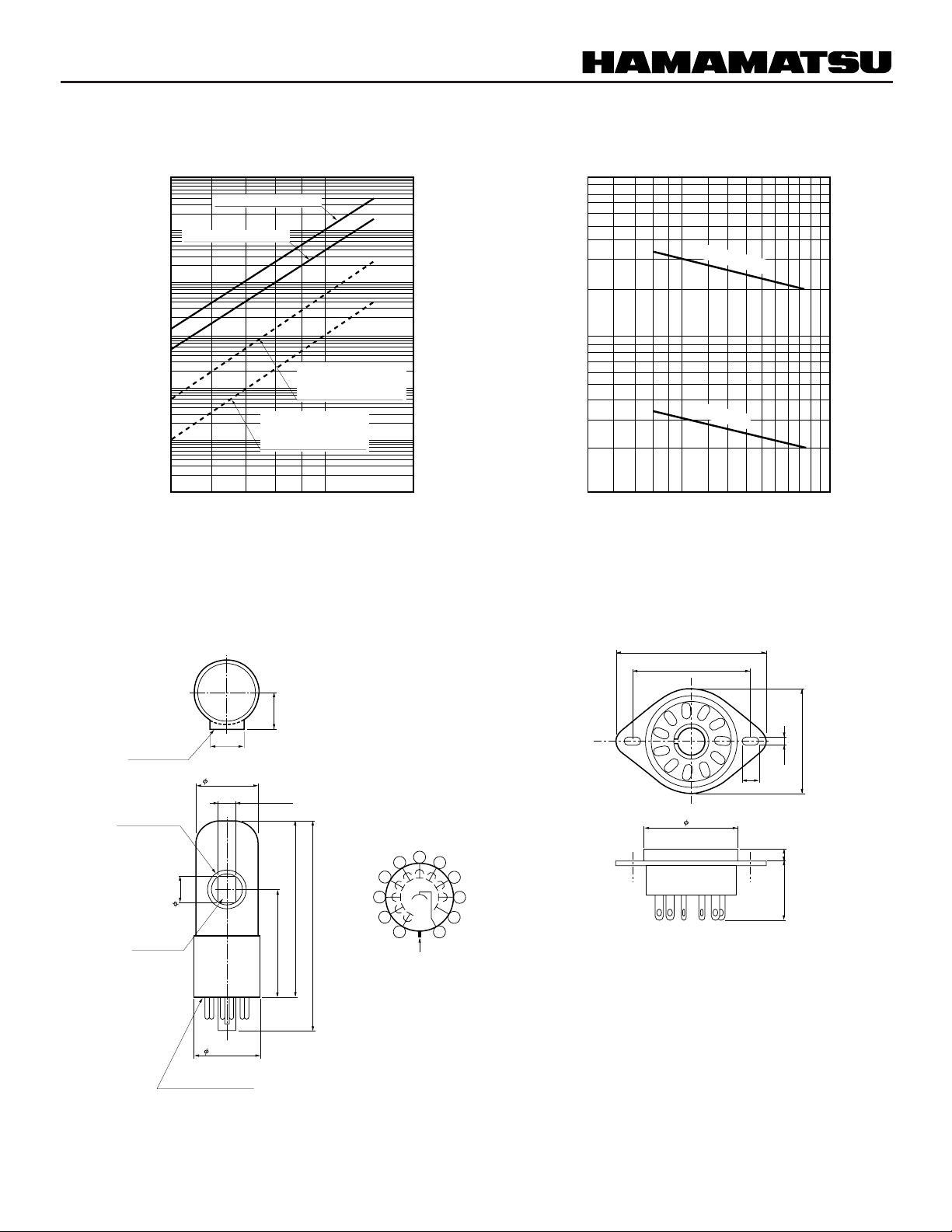
Figure 2: Typical Gain and Anode Radiant Sensitivity
Figure 3: Typical T ime Response
TPMSB0200EA
8
10
8
10
R8486 TYPICAL GAIN
7
10
R8487 TYPICAL GAIN
6
10
5
10
R8486 TYPICAL
4
10
3
ANODE RADIANT SENSITIVITY (A/W)
10
2
10
500 700 1000
ANODE SENSITIVITY
(at 254 nm)
R8487 TYPICAL
ANODE SENSITIVITY
(at 121.6 nm)
1500
7
10
6
10
5
10
GAIN
4
10
3
10
2
10
SUPPLY VOLTAGE (V)
Figure 4: Dimensional Outline and Basing Diagram (Unit: mm)
TPMSB0004EB
100
80
60
40
TRANSIT TIME
20
10
8
TIME (ns)
6
4
RISE TIME
2
1
300
500 700
1000 1500
SUPPLY VOLTAGE (V)
Figure 5: Socket E678-11A (Option) (Unit: mm)
FACE PLATE
MgF2 WINDOW
PHOTOCATHODE
20 MAX.
28.5 ± 1.5
12 MIN.
32.2 ± 0.5
11 PIN BASE
JEDEC No. B11-88
20 MAX.
8 MIN.
80 MAX.
49.0 ± 2.5
94 MAX.
DY6
DY5
6
5
DY4
4
3
DY3
2
DY2
1
DY1
DIRECTION OF LIGHT
49
38
33
3.5
5
29
DY7
7
DY8
8
9
DY9
10
P
11
K
TPMSA0042EA
418
TACCA0064EA
NOTE: There is a 2 mm diameter hole to exhaust inner air on the plastic base.
Page 4

PHOTOMULTIPLIER TUBES R8486, R8487
Warning—Personal Safety Hazards
Electrical Shock—Operating voltages applies to this
device present a shock hazard.
HAMAMATSU PHOTONICS K.K., Electron Tube Center
314-5, Shimokanzo, Toyooka-village, Iwata-gun, Shizuoka-ken, 438-0193, Japan, Telephone: (81)539/62-5248, Fax: (81)539/62-2205
U.S.A.:
Hamamatsu Corporation: 360 Foothill Road, P. O. Box 6910, Bridgewater. N.J. 08807-0910, U.S.A., Telephone: (1)908-231-0960, Fax: (1)908-231-1218 E-mail: [email protected]
Germany:
Hamamatsu Photonics Deutschland GmbH: Arzbergerstr. 10, D-82211 Herrsching am Ammersee, Germany, Telephone: (49)8152-375-0, Fax: (49)8152-2658 E-mail: [email protected]
France:
Hamamatsu Photonics France S.A.R.L.: 8, Rue du Saule Trapu, Parc du Moulin de Massy, 91882 Massy Cedex, France, Telephone: (33)1 69 53 71 00, Fax: (33)1 69 53 71 10 E-mail: [email protected]
United Kingdom:
North Europe:
Italy:
Hamamatsu Photonics UK Limited: 2 Howard Court, 10 Tewin Road Welwyn Garden City Hertfordshire AL7 1BW, United Kingdom, Telephone: 44-(0)1707-294888, Fax: 44(0)1707-325777 E-mail: [email protected]
Hamamatsu Photonics Norden AB: Smidesvägen 12, SE-171-41 SOLNA, Sweden, Telephone: (46)8-509-031-00, Fax: (46)8-509-031-01 E-mail: [email protected]
Hamamatsu Photonics Italia: S.R.L.: Strada della Moia, 1/E, 20020 Arese, (Milano), Italy, Telephone: (39)02-935 81 733, Fax: (39)02-935 81 741 E-mail: [email protected]
HOMEPAGE URL http://www.hamamatsu.com
TPMS1070E01
FEB. 2001 IP
Printed in Japan (1,000)
 Loading...