

Page 1
R2862A Digital 2R Receiver OC-192/STM-64
Description
The R2862A 10 Gbits/s receiver is a PIN receiver
with integrated transimpedance amplifier (TIA) and
limiting amplifier (LA). An integrated voltage regulator
provides accurate control of the TIA, thus allowing
the TIA to be powered externally by a wide range of
voltages. In addition, a threshold adjust provides the
capability to change the eye crossing point. The
threshold pin may be left open, in which case the LA
self-regulates to its nominal half-way setting.
Preliminary Data Sheet
October 2001
Features
■
Integr a t ed l im it i ng a m pl i fier , 55 0 mV p - p out p ut t yp i cal
■
High sensitivity, –20 dBm typical
■
Wide dynamic range, 2 dBm overload typical
■
Hermetically sealed
■
ac-coupled output
■
Threshold adjust for eye crossing
Applications
■
10 Gbits/s short, intermediate, and long-haul systems
■
SONET/SDH equipment
Agere Systems Inc. offers several 1R and 2R highspeed receiver components for 10 Gbits/s and
12.5 Gbits/s applications. APD and PIN versions are
available in a 6-pin hermetic package with coaxial
output. In addition, Agere Systems also offers a PIN
receiver with coplanar waveguide in a multisource
agreement form-factor or a smaller, space-sensitive
package. For more information about the complete
line of high-speed receiver products, please visit the
Agere Systems' website at www.agere.com/opto.
■
Datacom equipment
Page 2
Preliminary Data Sheet
R2862A Digital 2R Receiver OC-192/STM-64 October 2001
Absolute Maximum Ratings
Stresses in excess of the absolute maximum ratings can cause permanent damage to the device. These are absolute stress ratings only. Functional operation of the device is not implied at these or any other conditions in excess
of those given in the operational sections of the data sheet. Exposure to absolute maximum ratings for extended
periods can adversely affect device reliability.
Parameter Symbol Min Max Unit
Storage Case Temperature Range T
TIA Supply Voltage V
TIA and LA Supply Voltage V
Photodiode Bias Voltage V
Threshold Adjust Voltage V
Optical Input Power P
stg
CC
EE
PD
T
IN
ESD-susceptibility, dc pins* — — 500 (target) V
ESD-susceptibility, RF pins* — — 75 V
* Based on human-body model of R = 1500 Ω and C =100 pF. In general, precautions should be taken to avoid damage to the device.
–40 85 °C
GND 6 V
–6 GND V
GND 14 V
–2 2 V
—4dBm
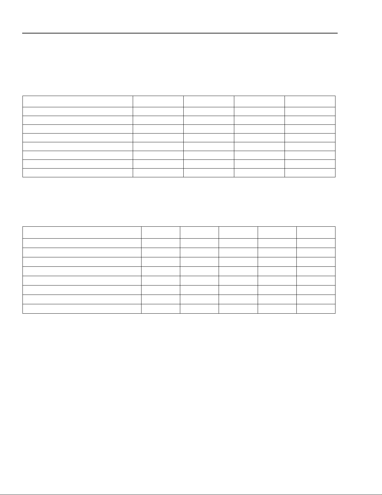
Recommended Operating Conditions
Table 1. Recommended Operating Conditions
Parameter Symbol Min Typ Max Unit
Bit Rate BR — 9.953 10.7 Gbits/s
Operating Case Temperature Range T
TIA Supply Voltage V
TIA and LA Supply Voltage V
Photodiode Bias Voltage V
Threshold Adjust Voltage V
Optical Wavelength
Optical Input Power P
OP
CC
EE
PD
T
λ
IN
–5 25 70 °C
3.1 5 5.25 V
–5.5 –5.2 –4.75 V
3.1 5 5.25 V
–1.5 Open 1.5 V
1280 — 1580 nm
–19 — 0 dBm
2
Agere System s Inc.
Page 3

Preliminary Data Sheet
October 2001 R2862A Digital 2R Receiver OC-192/STM-64
Electrical/Optical Characteristics
Table 2. Electrical/Optical Characteristics
(Specified characteristics apply for the operating conditions in Table 1
at BOL, unless noted otherwise.)
Parameter Symbol Condition Min Typ Max Unit
Sensitivity* —
Overload* —
–12
10
BER, PRBS 2
–12
10
BER, PRBS 2
Responsivity R –5 °C to +70 °C case
25 °C case
Dark Current I
Output Voltage V
D
OUT
Ext. Ratio = 10 dB, PRBS 231 – 1,
25 °C case — — 1.0 nA
31
31
– 1
– 1
— –20 –18.5 dBm
0 2 — dBm
0.65
0.7
0.75
0.8
—
—
300 550 750 mVp-p
Pin = –19 dBm to 0 dBm
Transimpedance, Small
Z
T
PIN = –25 dBm — 100 — k
Signal
Eye Crossing* — –19 dBm, V
Eye Crossing:*
V
= –1 V
T
V
= 1 V
T
Rise/Fall Time*
—
t
R/tF
= –19 dBm
P
IN
P
= –19 dBm
IN
PIN = –19 dBm — 20 35 ps
open 35 50 65 %
T
60
—
—
—
—
40
(20%—80%)
Bandwidth, Small Signal f
3 dB
PIN = –25 dBm,
79—GHz
–3 dB Relative to 300 MHz
Low-frequency Cutoff — P
= –25 dBm,
IN
——30kHz
Relative to 300 MHz
Supply Current, V
Supply Current, V
CC
EE
I
I
CC
EE
Logic Sense — — — Non-
— — 80 120 mA
— — 225 300 mA
——
inverting
Optical Return Loss RL Not Including Connector 27 — — dB
Agilent
* Test transmitter: external modulator, BW > 10 GHz, λ = 1550 ± 30 nm; extinction ratio > 10 dB (e.g.,
™
Model 83433).
A/W
A/W
Ω
%
%
Agere Systems Inc.
3
Page 4

Preliminary Data Sheet
R2862A Digital 2R Receiver OC-192/STM-64 October 2001
Pin Information
Table 3. Pin Descriptions
Pin No. Symbol Function
1 NC No Connect
2V
3V
4V
5V
CC
PD
EE
T
Threshold adjust for LA; may be left open
TIA, via regulator
Photodiode
TIA and LA
6 GND Ground
Block Diagram
VOLTAGE
REGULATOR
PHOTODIODE
PIN
1
NC
TRANSIM.
AMP
PROTECTION
DIODE
2
CC
V
LIMITING
AMP
3
PD
V
4
EE
V
5
T
V
6
GND
RF
OUT
1-xxxx
4
Agere System s Inc.
Page 5

Preliminary Data Sheet
October 2001 R2862A Digital 2R Receiver OC-192/STM-64
Outline Diagram
Dimensions are in inches and (millimeters).
Mechanical tolerances, unless otherwise specified, are: 0.XX = ±0.01 (±0.25), 0.XXX = ±0.007 (±0.18)
0.26
(7.00)
0.29
(7.40)
K-CONNECTOR
0.31
(7.90)
P*
™
0.41
(10.40)
0.58
(14.70)
0.19 ± 0.03
(5.00 ± 0.80)
1 METER MIN.
(2.50)
4X 0.094 (2.40)
0.08 ± 0.03
(2.00 ± 0.80)
0.70 ± 0.03
(18.00 ± 0.80)
0.10
0.15
(3.80)
PIN #1
1.24 (31.50)
1.04 (26.40)
0.84 (21.30)
0.20
(5.10)
0.33 ± 0.03
(8.00 ± 0.80)
5X 0.10
(2.50)
6X 0.02
(0.50)
.
0.78
(19.80)
0.17
(4.30)
* P = pin length.
Agere Systems Inc.
0.225
(5.70)
0.40
(1.00)
0.174
(4.40)
1-1169(F).b
5
Page 6

Preliminary Data Sheet
R2862A Digital 2R Receiver OC-192/STM-64 October 2001
Ordering Information
For ordering information, please contact an account manager at Opto West, Agere Systems Inc., 1-800-362-3891
(for sales staff, please press option 2).
Agilent
is a trademark of Agilent Technologies, Inc.
K-Connector
For additional information, contact your Agere Systems Account Ma na ger or the following:
INTERNET:
E-MAIL:
N. AMERICA: Agere Systems Inc., 555 Union Boulevard, Room 30L-15P-BA, Allentown, PA 18109-3286
ASIA: Agere Systems Hong Kong Ltd., Suites 3201 & 3210-12, 32/F, Tower 2, The Gateway, Harbour City, Kowloon
EUROPE:
Agere Systems Inc. reserves the right to make changes to the product(s) or information contained herein without notice. No liability is assumed as a result of their use or application.
Copyright © 2001 Agere Systems Inc.
All Rights Reserved
October 2001
DS01-322OPTO
is a trademark of Anritsu Company.
http://www.agere.com
docmaster@agere.com
1-800-372-2447
Tel. (852) 3129-2000
CHINA:
JAP AN:
Tel. (44) 7000 624624
, FAX 610-712-4106 (In CANADA:
(86) 21-5047-12 12
(81) 3-5421-160 0
, FAX (852) 3129-2020
(Shanghai),
(Tokyo), KOREA:
, FAX (44) 1344 488 045
1-800-553-2448
(86) 10-6522-5566
(82) 2-767-1850
, FAX 610-712-4106)
(Beijing),
(86) 755-695-7224
(Seoul), SINGAPORE:
(Shenzhen)
(65) 778-8833
, TAIWAN:
(886) 2-2725-5858
(Taipei)
 Loading...