

Page 1
R2860F Digital Receiver OC-192/STM-64
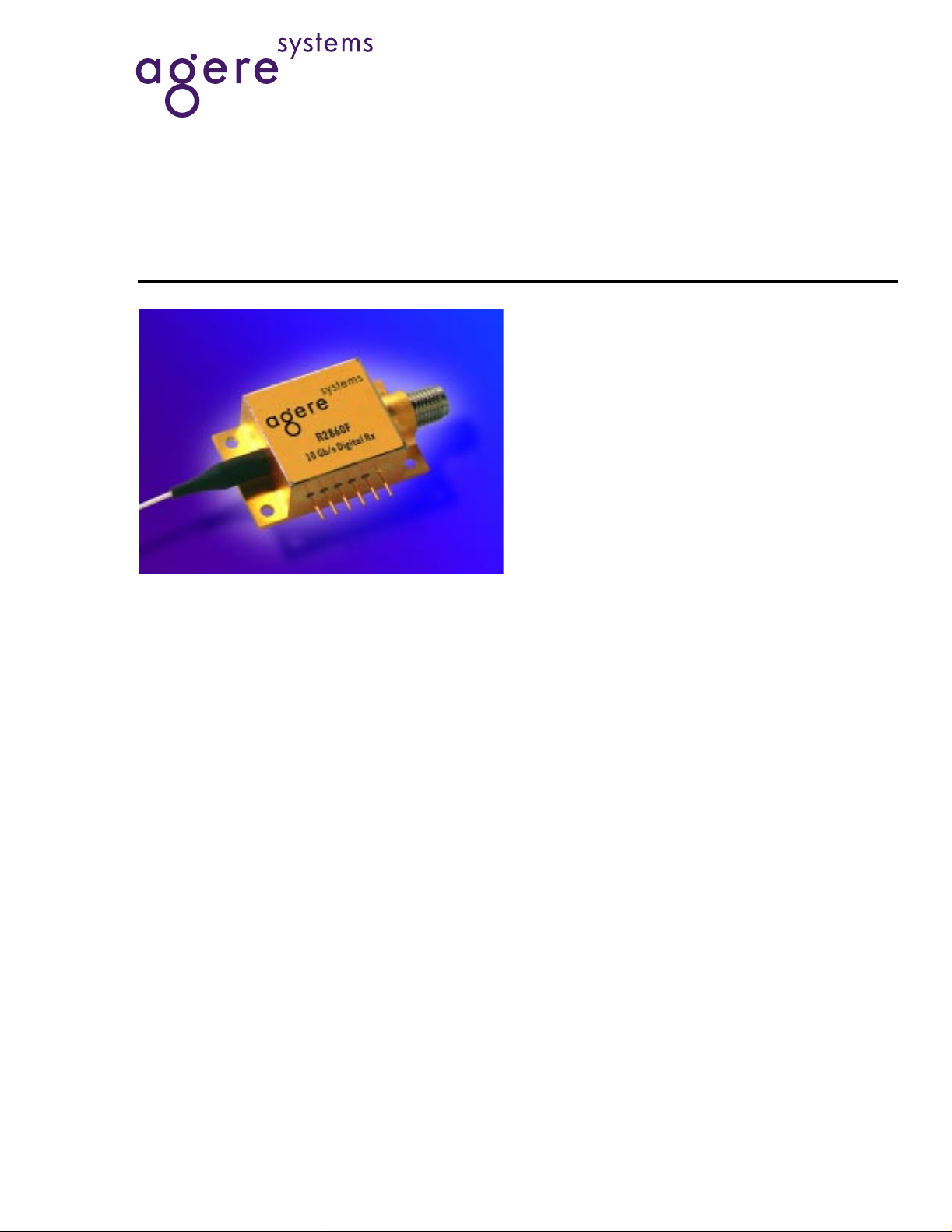
Description
The R2860F receiver module incorporates a highspeed planar PIN diode and a GaAs PHEMT preamplifier to provide exceptionally high performance. The
unit provides high bandwidth and sensitivity to operate with long, dispersive fibers, plus wide dynamic
range for operation over a variety of loss budgets.
High transimpedance coupled with a nonquantizing
limiting buffer output provides high gain while limiting
the maximum output signal swing, thereby simplifying
the interface to subsequent stages.
Data Sheet, Rev. 2
September 2001
Features
■
High sensitivity, –20 dBm typical
■
Wide dynamic range, 2 dBm overload typical
■
High transimpedance, 2000 Ω typical
■
Hermetically sealed
■
Optimized for multiple supply voltages, including
±5 V dual supplies, 8 V only, or –8 V only
■
ac-coupled output
Applications
■
10 Gbits/s short, intermediate, and long-haul systems
■
SONET/SDH equipment
■
Datacom equipment
Agere Systems Inc. offers several 1R and 2R highspeed receiver components for 10 Gbits/s and
12.5 Gbits/s applications. APD and PIN versions are
available in a 6-pin hermetic package with coaxial
output. In addition, Agere Systems also offers a PIN
receiver with coplanar waveguide in a multisource
agreement form-factor or a smaller, space sensitive
package. For more information about the complete
line of high-speed receiver products, please visit the
Agere Systems' website at www.agere.com/opto.
Page 2

Data Sheet, Rev. 2
R2860F Digital Receiver OC-192/STM-64 September 2001
Absolute Maximum Ratings
Stresses in excess of the absolute maximum ratings can cause permanent damage to the device. These are absolute stress ratings only. Functional operation of the device is not implied at these or any other conditions in excess
of those given in the operational sections of the data sheet. Exposure to absolute maximum ratings for extended
periods can adversely affect device reliability.
Parameter Symbol Min Max Unit
Operating Temperature Range T
OP
–5 70 °C
Storage Case Temperature Range Tstg –40 85 °C
Preamp Supply Voltage V
Photodiode Bias Voltage V
CC-VEE
PD-VEE
Optical Input Power P
IN
—12V
—20V
—4dBm
Electrical/Optical Characteristics
Table 1. Electrical and Optical Characteristics
(25 °C Case Temperature)
Parameter Symbol Min Typ Max Unit
Optical Wavelength Range λ 1280 — 1580 nm
-10
Sensitivity (10
Overload (10
BER, PRBS 223 – 1) — — –20 –18 dBm
-13
BER, PRBS 223 –1) — 0 2 — dBm
Responsivity R 0.7 0.8 — A/W
Dark Current I
D
——1.0nA
High-Frequency Cutoff — 8.0 9.0 — GHz
Low-Frequency Cutoff — — — 30 kHz
Transimpedance Z 1400 2000 — Ω
Maximum ac Output Voltage Swing — — 800 — mVp-p
RF Output Return Loss
RL
RF
— — 10 dB
(0.1 GHz—5 GHz)
Optical Return Loss RL 27 — — dB
Logic Sense — — Noninverting — —
Photodiode Supply Voltage* V
Positive Supply Voltage* V
Negative Supply Voltage* V
Supply Current I
* Floating supply capability allows alternate powering configurations such as VPD = 8 V, VCC = 8 V, and VEE = GND, or V
EE
= –8 V.
and V
CC
PD
CC
EE
, –I
EE
357V
455.5V
–5.5 –5 –4 V
—80120mA
PD
= GND, V
CC
= GND,
2
Agere System s Inc.
Page 3

Data Sheet, Rev. 2
September 2001 R2860F Digital Receiver OC-192/STM-64
Pin Information
Table 2. Pin Descriptions
Pin No. Description
1NC
2V
3V
4V
CC
PD
EE
5NC
6 Ground
Block Diagram
VOLTAGE
IN
REGULATOR
OUT1 OUT2
PIN
PHOTODIODE
Characteristic Curve
OUTPUT VOLTAGE (mVp—p)
1
NC
1000
100
10
CC
V
TRANSIMPEDANCE
AMPLIFIER
IN OUT
PROTECTION
DIODE
2
CC
V
–18 –16 –14 –12 –10 –8 –4 –2
–20
3
PD
V
INPUT OPTICAL POWER (dBm, NRZ)
4
EE
V
LIMITING
5
NC
OUTPUT
BUFFER
OUTIN
6
GND
RF OUT
1-1170 (F).c
0–6
1-1172 (F).a
Figure 1. R2860F Typical Electrical Output Voltage vs. Optical Input Power
Agere Systems Inc.
3
Page 4

Data Sheet, Rev. 2
R2860F Digital Receiver OC-192/STM-64 September 2001
Outline Diagram
Dimensions are in inches and (millimeters).
0.19 ± 0.03
(5.00 ± 0.80)
1 METER MIN.
4X 0.094 (2.40)
0.08 ± 0.03
(2.00 ± 0.80)
0.70 ± 0.03
(18.00 ± 0.80)
0.10
(2.50)
0.15
(3.80)
PIN #1
1.24 (31.50)
1.04 (26.40)
0.84 (21.30)
0.20
(5.10)
0.33 ± 0.03
(8.00 ± 0.80)
5X 0.10
(2.50)
6X 0.02
(0.50)
0.26
(7.00)
0.29
(7.40)
0.20
(5.00)
K-CONNECTOR
0.31
(7.90)
™
0.41
(10.40)
0.58
(14.70)
0.78
(19.80)
0.40
0.17
(4.30)
0.225
(5.70)
4
(1.00)
0.174
(4.40)
1-1169 (F).d
Agere System s Inc.
Page 5

Data Sheet, Rev. 2
September 2001 R2860F Digital Receiver OC-192/STM-64
Ordering Information
Table 3. Ordering Information
1
Device Code Description Connector Pigtail Comcode
R2860F023 Digital Receiver
Ω
1400
min. TIA gain,
FC/SPC,
Standard
SMF-28
™ (1 m min.) 108870312
ac-coupled output
R2860F040 Digital Receiver
SC/UPC
SMF-28
(1 m min.) 108870320
1400 Ω min. TIA gain,
ac-coupled output
1. Other options available. For additional ordering information, please contact an account manager at Opto West, Agere Systems Inc., 1-800362-3891 (for sales staff, please press option 2).
Agere Systems Inc.
5
Page 6

Data Sheet, Rev. 2
R2860F Digital Receiver OC-192/STM-64 September 2001
K-Connector
SMF-28
For additional information, contact your Agere Systems Account Ma na ger or the following:
INTERNET:
E-MAIL:
N. AMERICA: Agere Systems Inc., 555 Union Boulevard, Room 30L-15P-BA, Allentown, PA 18109-3286
ASIA: Agere Systems Hong Kong Ltd., Suites 3201 & 3210-12, 32/F, Tower 2, The Gateway, Harbour City, Kowloon
EUROPE:
Agere Systems Inc. reserves the right to make changes to the product(s) or information contained herein without notice. No liability is assumed as a result of their use or application.
Copyright © 2001 Agere Systems Inc.
All Rights Reserved
September 2001
DS00-278OPTO-2 (Replaces DS00-278OPTO-1)
is a trademark of Anritsu Company.
is a trademark of Corning Incorporated.
http://www.agere.com
docmaster@agere.com
1-800-372-2447
Tel. (852) 3129-2000
CHINA:
JAP AN:
Tel. (44) 7000 624624
, FAX 610-712-4106 (In CANADA:
(86) 21-5047-12 12
(81) 3-5421-160 0
, FAX (852) 3129-20 20
(Shanghai),
(Tokyo), KOREA:
, FAX (44) 1344 488 045
1-800-553-2448
(86) 10-6522-5566
(82) 2-767-1850
, FAX 610-712-4106)
(Beijing),
(86) 755-695-7224
(Seoul), SINGAPORE:
(Shenzhen)
(65) 778-8833
, TAIWAN:
(886) 2-2725-5858
(Taipei)
 Loading...