

Datasheet QTLP670C-AG, QTLP670C-E, QTLP670C-IB, QTLP670C-IG, QTLP670C-IW Datasheet (Fairchild Semiconductor)
...Page 1
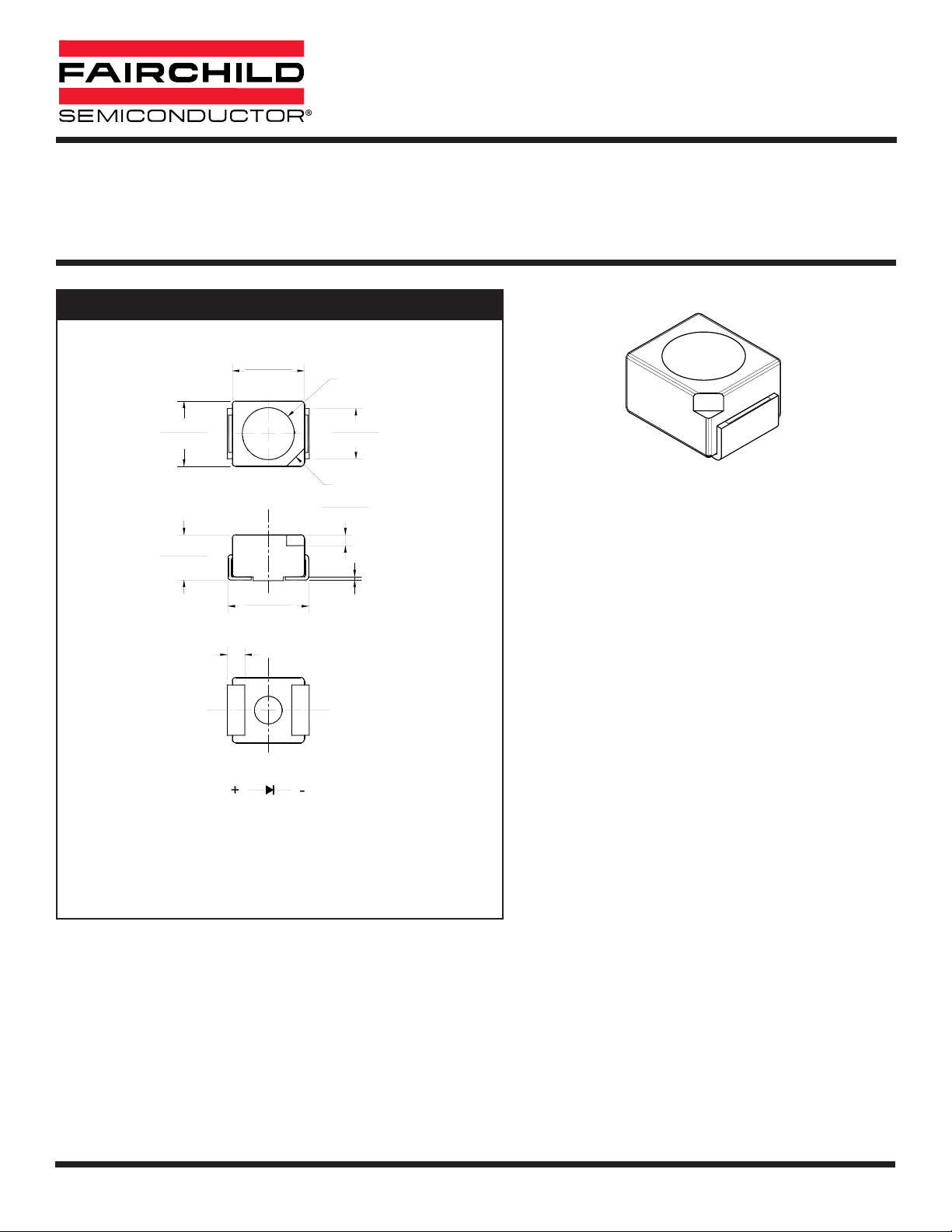
DESCRIPTION
These surface mount LEDs are designed with flat top and sides for the ease of pick-and-place by automatic placement equipment.
They are compatible with convective IR and vapor phase reflow soldering. The package size and configuration conform to EIA-535
BAAC standard specification for case size 3528 tantalum capacitor. These LEDs are ideal for backlighting and optical coupling into
light pipes.
0.118 (3.0)
0.102 (2.6)
0.091 (2.3)
0.083 (2.1)
0.146 (3.7)
0.130 (3.3)
0.006 (0.15)
0.024 (0.6)
0.016 (0.4)
0.083 (2.1)
0.067 (1.7)
CATHODE
0.130 (3.3)
0.114 (2.9)
Ø0.094 [Ø2.4]
0.032 (0.8)
BOTTOM
CATHODE
SIDE
TOP
POLARITY
NOTE:
Dimensions for all drawings are in inches (mm).
PACKAGE DIMENSIONS
QTLP670C-T Red QTLP670C-S Red QTLP670C-R Red
QTLP670C-E Orange QTLP670C-O Yellow-Orange QTLP670C-Y Yellow
QTLP670C-AG Yellow-Green QTLP670C-IG True Green QTLP670C-IB Blue
QTLP670C-IW White
APPLICATIONS
• Automotive interior lighting
• Status indication for consumer electronics and office
equipment
SURFACE MOUNT LED LAMP
SUPER BRIGHT PLCC-2
FEATURES
• AllnGaP technology for -T, -S, -R, -E, -O, -Y and -AG • Water clear optics
• InGaN/SiC technology for -IG, -IB and -IW • Available in 0.315” (8mm) width tape on
• Wide viewing angle of 120° 7” (178mm) diameter reel; 2,000 units per reel
2001 Fairchild Semiconductor Corporation
DS300236 8/31/01 1 OF 8 www.fairchildsemi.com
Page 2
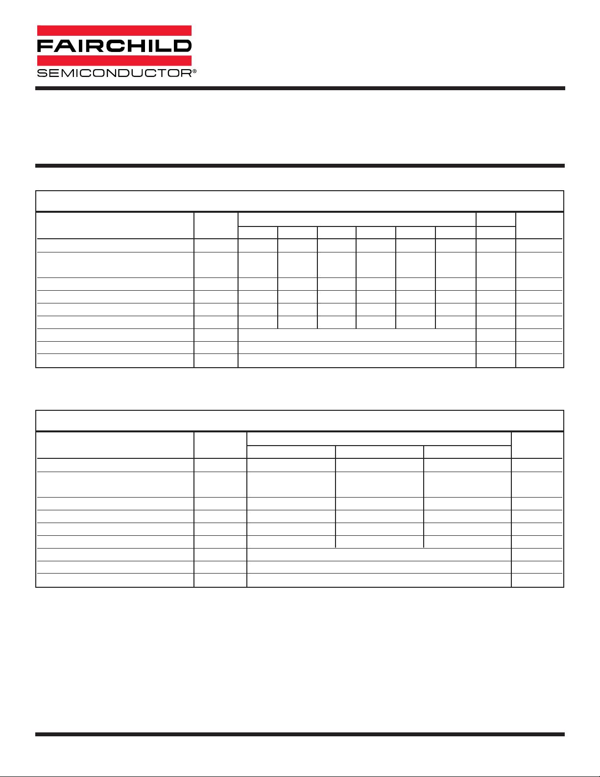
Parameter Symbol
QTLP670C
Units
-T -S -R -E -O -Y -AG
Continuous Forward Current I
F
30 30 30 30 30 25 30 mA
Peak Forward Current
I
FM
160 160 160 160 160 120 160 mA
(f = 1.0 KHz, Duty Factor = 1/10)
Reverse Voltage (IR = 10 µA) V
R
5555 555 V
Power Dissipation P
D
72 72 72 72 72 60 72 mW
Junction Temperature T
J
100 100 100 100 100 100 100 °C
Thermal Resistance (Junction-Air) R
th JA
500 500 500 500 500 500 500 K/W
Operating Temperature T
OPR
-40 to +95 °C
Storage Temperature T
STG
-40 to +100 °C
Lead Soldering Time T
SOL
260 for 5 sec °C
ABSOLUTE MAXIMUM RATINGS
(T
A =25°C Unless otherwise specified)
Parameter Symbol
QTLP670C
Units
-IB -IG -IW
Continuous Forward Current I
F
30 30 20 mA
Peak Forward Current
I
FM
100 100 70 mA
(f = 1.0 KHz, Duty Factor = 1/10)
Reverse Voltage (IR = 10 µA) V
R
555V
Power Dissipation P
D
120 120 80 mW
Junction Temperature T
J
125 125 125 °C
Thermal Resistance Junction-Air R
th JA
400 400 400 K/W
Operating Temperature T
OPR
-40 to +95 °C
Storage Temperature T
STG
-40 to +100 °C
Lead Soldering Time T
SOL
260 for 5 sec °C
ABSOLUTE MAXIMUM RATINGS
(T
A =25°C Unless otherwise specified)
SURFACE MOUNT LED LAMP
SUPER BRIGHT PLCC-2
QTLP670C-T Red QTLP670C-S Red QTLP670C-R Red
QTLP670C-E Orange QTLP670C-O Yellow-Orange QTLP670C-Y Yellow
QTLP670C-AG Yellow-Green QTLP670C-IG True Green QTLP670C-IB Blue
QTLP670C-IW White
www.fairchildsemi.com 2 OF 8 8/31/01 DS300236
Page 3

Part Number Symbol
QTLP670C
Condition
-T -S -R -E -O -Y -AG
Luminous Intensity (mcd)
Minimum I
V
20 25 25 25 25 25 15 IF= 20mA
Typical 45 65 65 65 65 65 30
Forward Voltage (V)
Maximum V
F
2.4 2.4 2.4 2.4 2.4 2.4 2.4 IF= 20mA
Typical 2.0 2.0 2.0 2.0 2.0 2.0 2.0
Wavelength (nm)
D
P
Peak 650 640 630 620 610 590 575 IF= 20mA
Dominant D
D
640 632 624 615 605 589 573
Spectral Line Half Width (nm) D 20 20 20 18 18 15 20 IF= 20mA
Viewing Angle (°) 201/
2
120 120 120 120 120 120 120 IF= 20mA
ELECTRICAL / OPTICAL CHARACTERISTICS
(T
A =25°C)
SURFACE MOUNT LED LAMP
SUPER BRIGHT PLCC-2
Part Number Symbol
QTLP670C
Condition
-IB -IG -IW
Luminous Intensity (mcd)
Minimum I
V
30 75 100 IF= 20mA
Typical 60 115 250
Forward Voltage (V)
Maximum V
F
4.0 4.0 4.0 IF= 20mA
Typical 3.5 3.5 3.5
Wavelength (nm)
D
P
Peak 465 520 — IF= 20mA
Dominant D
D
470 525 —
Chromaticity Coordinate x,y — — x = 0.30, y = 0.31 IF= 20mA
Spectral Line Half Width (nm) D 25 35 — IF= 20mA
Viewing Angle (°) 201/
2
120 120 120 IF= 20mA
ELECTRICAL / OPTICAL CHARACTERISTICS
(T
A =25°C)
QTLP670C-T Red QTLP670C-S Red QTLP670C-R Red
QTLP670C-E Orange QTLP670C-O Yellow-Orange QTLP670C-Y Yellow
QTLP670C-AG Yellow-Green QTLP670C-IG True Green QTLP670C-IB Blue
QTLP670C-IW White
DS300236 8/31/01 3 OF 8 www.fairchildsemi.com
Page 4

TYPICAL PERFORMANCE CURVES (QTLP670C-T, -S, -R, -E, -O, -Y and -AG)
SURFACE MOUNT LED LAMP
SUPER BRIGHT PLCC-2
QTLP670C-T Red QTLP670C-S Red QTLP670C-R Red
QTLP670C-E Orange QTLP670C-O Yellow-Orange QTLP670C-Y Yellow
QTLP670C-AG Yellow-Green QTLP670C-IG True Green QTLP670C-IB Blue
QTLP670C-IW White
www.fairchildsemi.com 4 OF 8 8/31/01 DS300236
Fig. 1 Forward Current vs. Forward Voltage
Fig. 2 Relative Luminous Intensity
vs. DC Forward Current
100
90
80
70
60
50
40
30
20
- FORWARD CURRENT (mA)
10
F
I
0
1.0 1.5 2.0 2.5 3.0
VF - FORWARD VOLTAGE (V)
2.5
2.0
1.5
1.0
0.5
(NORMALIZED AT 20 mA)I
RELATIVE LUMNOUS INTENSITY
0.0
010203040
IF - DC FORWARD CURRENT (mA)
Fig. 3 Relative Intensity vs. Peak Wavelength
1.0
0.5
RELATIVE INTENSITY
0
500 550 600 650 700
AG Y O E R S T
WAVELENGTH (nm)
50
Fig.4 Radiation Diagram
Fig.5 Maximum Forward Current
vs. Ambient Temperature
50
0˚
-10˚ 10˚
-20˚ 20˚
-30˚ 30˚
-40˚ 40˚
-50˚ 50˚
-60˚ 60˚
-70˚ 70˚
-80˚ 80˚
-90˚ 90˚
1.0 0.8 0.6 0.4 0.2 0 0.2 0.4 0.6 0.8 1.0
REL. LUMINOUS INTENSITY (%)
40
30
20
10
- FORWARD CURRENT (mA)
F
0
0 255075100
T, S, R, E, O and AG
Y
AMBIENT TEMPERATURE TA (˚C)
Page 5

TYPICAL PERFORMANCE CURVES (QTLP670C-IG, -IB and -IW)
SURFACE MOUNT LED LAMP
SUPER BRIGHT PLCC-2
QTLP670C-T Red QTLP670C-S Red QTLP670C-R Red
QTLP670C-E Orange QTLP670C-O Yellow-Orange QTLP670C-Y Yellow
QTLP670C-AG Yellow-Green QTLP670C-IG True Green QTLP670C-IB Blue
QTLP670C-IW White
DS300236 8/31/01 5 OF 8 www.fairchildsemi.com
Fig. 1 Forward Current vs. Forward Voltage
Fig. 2 Relative Luminous Intensity
vs. DC Forward Current
100
90
80
70
60
50
40
30
20
- FORWARD CURRENT (mA)
10
F
I
0
2.0 2.5 3.0 3.5 4.0 4.5 5.0
VF - FORWARD VOLTAGE (V)
IG
IB and IW
2.5
2.0
1.5
1.0
0.5
(NORMALIZED AT 20 mA)I
RELATIVE LUMNOUS INTENSITY
0.0
01020304050
IF - DC FORWARD CURRENT (mA)
Fig. 3 Relative Intensity vs. Peak Wavelength
1.0
0.5
RELATIVE INTENSITY
0
400 450 500 550 600 650
IW IG
IB
WAVELENGTH (nm)
Fig.4 Radiation Diagram
0˚
-10˚ 10˚
-20˚ 20˚
-30˚ 30˚
-40˚ 40˚
-50˚ 50˚
-60˚ 60˚
-70˚ 70˚
-80˚ 80˚
-90˚ 90˚
1.0 0.8 0.6 0.4 0.2 0 0.2 0.4 0.6 0.8 1.0
REL. LUMINOUS INTENSITY (%)
Fig.5 Maximum Forward Current
vs. Ambient Temperature
50
40
30
20
10
- FORWARD CURRENT (mA)
F
0
0 255075100
AMBIENT TEMPERATURE T
IB IG
IW
(˚C)
A
Page 6

60 - 120 sec
Preheating
+5° C/s MAX
-5° C/s MAX
120 - 150° C MAX
5 sec MAX
soldering time
240° C MAX
0.071 [1.80]
2X
0.095 [2.41]
0.063 [1.60]
RECOMMENDED PRINTED CIRCUIT BOARD PATTERN
RECOMMENDED IR REFLOW SOLDERING PROFILE
SURFACE MOUNT LED LAMP
SUPER BRIGHT PLCC-2
QTLP670C-T Red QTLP670C-S Red QTLP670C-R Red
QTLP670C-E Orange QTLP670C-O Yellow-Orange QTLP670C-Y Yellow
QTLP670C-AG Yellow-Green QTLP670C-IG True Green QTLP670C-IB Blue
QTLP670C-IW White
www.fairchildsemi.com 6 OF 8 8/31/01 DS300236
Page 7

Ø12.75
Ø
62.0±0.5
Ø
180±1
2.5±0.5
11.0
+0.5
-0.0
+0.25
-0.0
+1.5
8.4
-0.0
2.50±0.5
Progressive direction
Polarity
1.75
2.0±0.05
Ø1.55.±05
3.5±0.05
4.0
0.23
4.0
Dimensional tolerance is ± 0.1mm unless otherwise specified
Angle: ± 0.5
8.0
Unit: mm
3.12 2.24
3.84
TAPE AND REEL DIMENSIONS
SURFACE MOUNT LED LAMP
SUPER BRIGHT PLCC-2
QTLP670C-T Red QTLP670C-S Red QTLP670C-R Red
QTLP670C-E Orange QTLP670C-O Yellow-Orange QTLP670C-Y Yellow
QTLP670C-AG Yellow-Green QTLP670C-IG True Green QTLP670C-IB Blue
QTLP670C-IW White
DS300236 8/31/01 7 OF 8 www.fairchildsemi.com
Page 8

DISCLAIMER
FAIRCHILD SEMICONDUCTOR RESERVES THE RIGHT TO MAKE CHANGES WITHOUT FURTHER NOTICE TO
ANY PRODUCTS HEREIN TO IMPROVE RELIABILITY, FUNCTION OR DESIGN. FAIRCHILD DOES NOT ASSUME
ANY LIABILITY ARISING OUT OF THE APPLICATION OR USE OF ANY PRODUCT OR CIRCUIT DESCRIBED
HEREIN; NEITHER DOES IT CONVEY ANY LICENSE UNDER ITS PATENT RIGHTS, NOR THE RIGHTS OF
OTHERS.
LIFE SUPPORT POLICY
FAIRCHILD’S PRODUCTS ARE NOT AUTHORIZED FOR USE AS CRITICAL COMPONENTS IN LIFE SUPPORT
DEVICES OR SYSTEMS WITHOUT THE EXPRESS WRITTEN APPROVAL OF THE PRESIDENT OF FAIRCHILD
SEMICONDUCTOR CORPORATION. As used herein:
1. Life support devices or systems are devices or
systems which, (a) are intended for surgical
implant into the body,or (b) support or sustain life,
and (c) whose failure to perform when properly
used in accordance with instructions for use provided
in labeling, can be reasonably expected to result in a
significant injury of the user.
2. A critical component in any component of a life support
device or system whose failure to perform can be
reasonably expected to cause the failure of the life
support device or system, or to affect its safety or
effectiveness.
SURFACE MOUNT LED LAMP
SUPER BRIGHT PLCC-2
QTLP670C-T Red QTLP670C-S Red QTLP670C-R Red
QTLP670C-E Orange QTLP670C-O Yellow-Orange QTLP670C-Y Yellow
QTLP670C-AG Yellow-Green QTLP670C-IG True Green QTLP670C-IB Blue
QTLP670C-IW White
www.fairchildsemi.com 8 OF 8 8/31/01 DS300236
 Loading...