

Page 1
PACKAGE DIMENSIONS DESCRIPTION
The QT Optoelectronics surface mount lamps are
designed with a flat top and sides for automatic
placement equipment. They are compatible with convective IR and vapor phase reflow soldering and conductive epoxy attachment process.
The package size and configuration conform to the
EIA–535 BAAC standard specification for case 3528
tantalum capacitor.
■ Non-diffused package for backlighting and
coupling to light pipe
■ Low package profile
■ Low power dissipation
■ Wide viewing angle
FEATURES
SMT LED LAMP
PLCC–2 PACKAGE
HIGH EFFICIENCY RED QTLP670C–2 GREEN QTLP670C–4
YELLOW QTLP670C–3 AlGaAs RED QTLP670C–7
HER Yellow Green AlGaAs Red
QTLP 670C–2 670C–3 670C–4 670C–7 Units
DC forward current, I
F
30 20 30 30 mA
Operating temperature range –40° C to +85° C
Storage temperature range –40° C to +100° C
Lead soldering time 5 seconds @ 260° C
Peak forward current1, I
F
160 160 160 200 mA
Power dissipation Pd (mW) 100 100 100 100 mW
Reversed Voltage (VR)5555V
ABSOLUTE MAXIMUM RATINGS (TA = 25° C Unless otherwise specified)
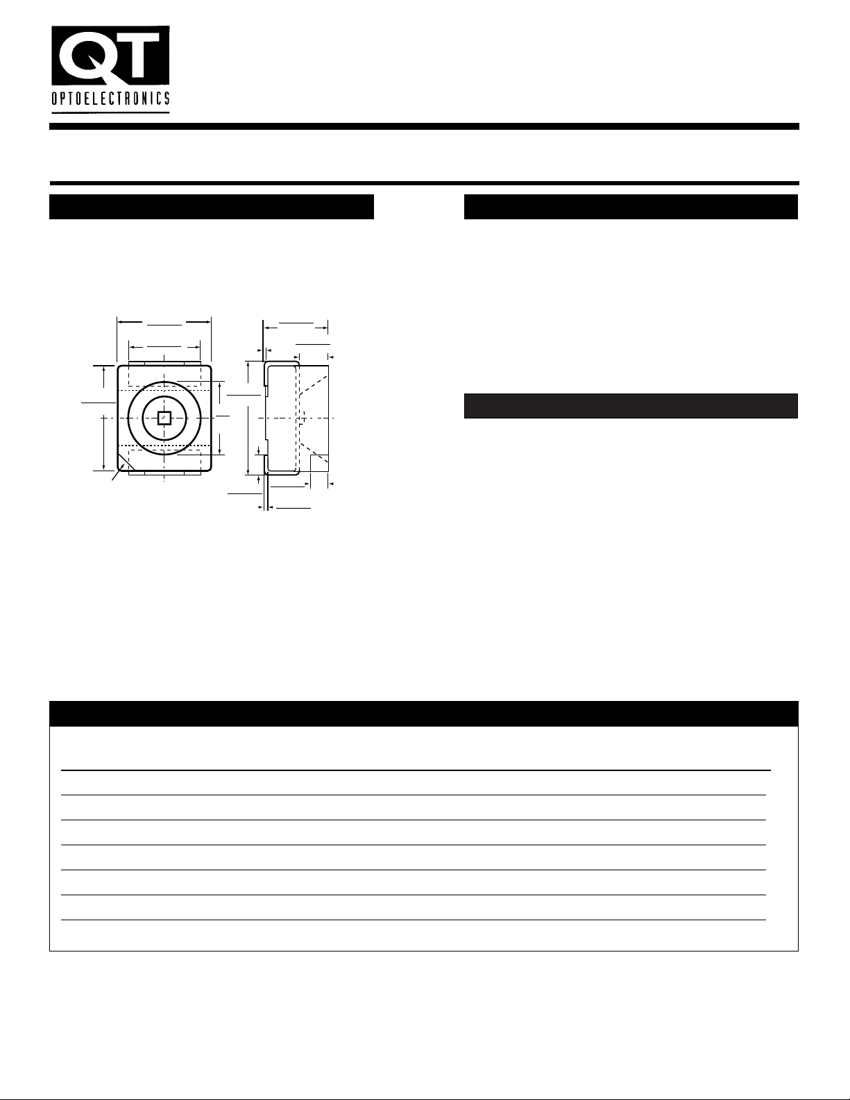
NOTE: ALL DIMENSIONS ARE IN INCHES (mm)
.118 (3.0)
.102 (2.6)
.091 (2.3)
.083 (2.1)
.134 (3.4)
.118 (3.0)
.094
(2.4)
CATHODE
ANODE FOR QTLP670C–7
.083 (2.1)
.067 (1.7)
Ø .04
(.1)
.142 (3.6)
.126 (3.2)
.043 (1.1)
.020 (.5)
.007 (.18)
.005 (.12)
.024 (.6)
.016 (.4)
.035 (.9)
.028 (.7)
Notes:
1. Measured @ f=1.0 kHz, Duty factor = 1/10
HER = High Efficiency Red
Page 2
SMT LED LAMP
PLCC–2 PACKAGE
AlGaAs
HER YELLOW GREEN RED TEST
QTLP 670C–2 670C–3 670C–4 670C–7 UNITS CONDITIONS
LUMINOUS INTENSITY
minimum 6 6 15 25 mcd I
F
= 20 mA
typical 10 10 25 40 mcd
FORWARD VOLTAGE
minimum 1.7 1.7 1.7 1.5 V I
F
= 20 mA
typical 2.0 2.0 2.1 1.7 V
maximum 2.8 2.8 2.8 2.4 V
PEAK WAVELENGTH 635 585 570 660 nm I
F
= 20 mA
SPECTRAL LINE HALF WIDTH 45 35 30 20 nm
VIEWING ANGLE 120° 120° 120° 120°
ELECTRO-OPTICAL CHARACTERISTICS (TA = 25° C Unless otherwise specified)
INDIVIDUAL COMPONENT CHARACTERISTICS
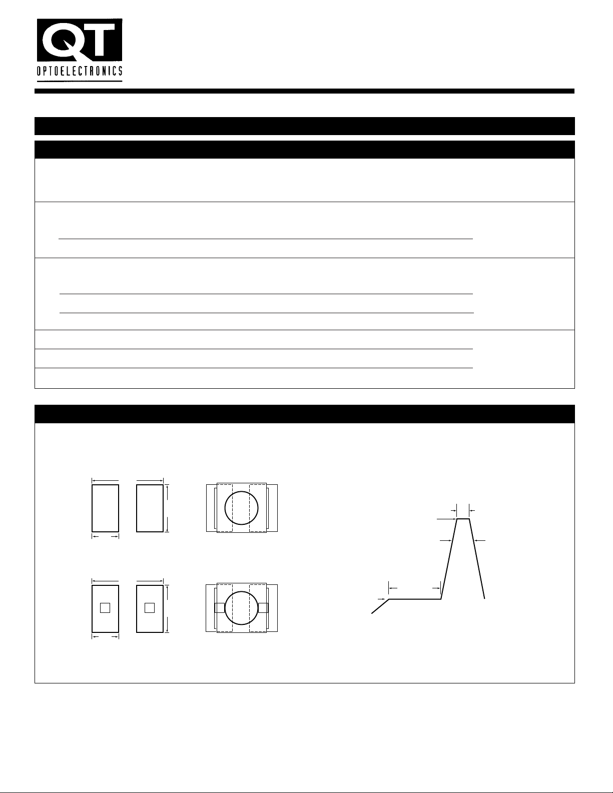
SOLDERING
FIG. 1 - Recommended Solder Pad Patterns
FIG. 2 - Recommended IR Reflow Soldering Profile
INFRARED VAPOR PHASE
REFLOW SOLDERING
4.45
(.175)
1.65
(.065)
4.45
(.175)
1.65
(.065)
0.64 (.025) SQ.
CENTERED HOLE
COMPONENT LOCATION
ON PAD
COMPONENT LOCATION
ON PAD
2.41
(.095)
2.41
(.095)
240° MAX
5 s MAX
soldering time
60 – 120 sec
Preheating
+5° C/s MAX –5° C/s MAX
120 – 150° C MAX
Notes:
All dimensions are in millimeters (inches).
HER = High Efficiency Red
Page 3

SMT LED LAMP
PLCC–2 PACKAGE
TYPICAL ELECTRO–OPTICAL CHARACTERISTIC CURVES (TA = 25° C)
FIG. 5 - Relative Luminous Intensity vs. Forward Current
FIG. 3 - Relative Intensity vs. Wavelength
FIG. 4 - Forward Current vs. Forward Voltage V
FIG. 6 - Relative Intensity vs. Angular Displacement
500
0
550 600 650 700 750
0.5
1.0
WAVELENGTH – nm
RELATIVE INTENSITY
GREEN YELLOW AlGaAs RED
HIGH
EFFICIENCY
RED
T
A
= 25° C
90
80
70
60
50
40
30
20
10
0
1.0 2.0 3.0 4.0 5.0
AlGaAs
RED
HER
YELLOW
GREEN
VF – FORWARD VOLTAGE – V
I
F
– FOWARED CURRENT – mA
0°
10°
20°
30°
40°
50°
60°
70°
90°
80°
1.0
.8
.6
.4
.2
10° 20° 30° 40° 50° 60° 70° 90°80° 100°
ø – OFF – AXIS ANGLE – DEGREES
NORMALIZED INTENSITY
IDC – DC CURRENT PER LED – mA
RELATIVE LUMINOUS INTENSITY
(NORMALIZED AT 20 mA)
005 10 15 20 25 30
0.5
1.0
1.5
2.0
AlGaAs
RED
HER
YELLOW
GREEN
Page 4

SMT LED LAMP
PLCC–2 PACKAGE
TAPE DIMENSIONS
Call QT Optoelectronics for more information or the phone number of your nearest distributor.
United States 800-533-6786 ■France 33 1/43.99.25.12 ■Germany 49 089/96.30.51■United Kingdom 44 [0] 1296/39.44.99 ■Asia/Pacific 603/735-2417
© 1996 QT Optoelectronics QT-013-A DS 103
8 MM TAPE AND REEL
NOTES:
1. All dimensions are in inches (mm).
2. Quantity/Reel: 2,000
3. When ordering tape and reel parts,
add suffix “.TR” to part number.
Components are packed in a heat-sealed,
moisture-proof aluminum bag.
NO
COMPONENTS
TRAILER
6.0 (150) MIN
User direction of feed
TAPE
COMPONENTS
OPERATOR
QT PART NUMBER
DATE CODE
TAPING DATE
ELEC. VALUE
TOLERANCE
QUANTITY
CUSTOMER PART NUMBER
STARTEND
NO
COMPONENTS
LEADER
6.0 (150) MIN
N A
C
OPERATOR
QT PART NUMBER
DATE CODE
TAPING DATE
ELEC. VALUE
TOLERANCE
QUANTITY
CUSTOMER PART NUMBER
Dimensions per ANSI/EIA
Standard RS-481
All dimensions are in
millimeters.
A
7.08 (180)
6.92 (176)
C
0.73 (18.5)
0.69 (17.5)
N 3.19 (81)
3.11 (79)
.45 (11.5)
T
.33 (8.5)
Thickness of top cover tape
T
.004 (.10) MAX
User direction of feed
Label this
side of reel
DIA
.157 (4.0)
.118 (3.0)
.063 (1.6)
DIA
CATHODE MARK
.055 (1.4)
POLARITY
.010 (.30)
.085 (2.16)
.161 (4.1)
.153 (3.9)
.161 (4.1)
.153 (3.9)
.081 (2.05)
.077 (1.95)
PROGRESSIVE DIRECTION
.073 (1.85)
.065 (1.65)
.142 (3.6)
.327 (8.3)
.303 (7.7)
 Loading...