

Page 1
QIP0640001
Powerex Inc., 200 Hillis St., Youngwood, PA 15697 (724)925-7272 Asymmetrical Half Bridge IGBT H-Series
Hermetic Module
400 Amperes/600 Volts
Description:
Hermetic Package TBD
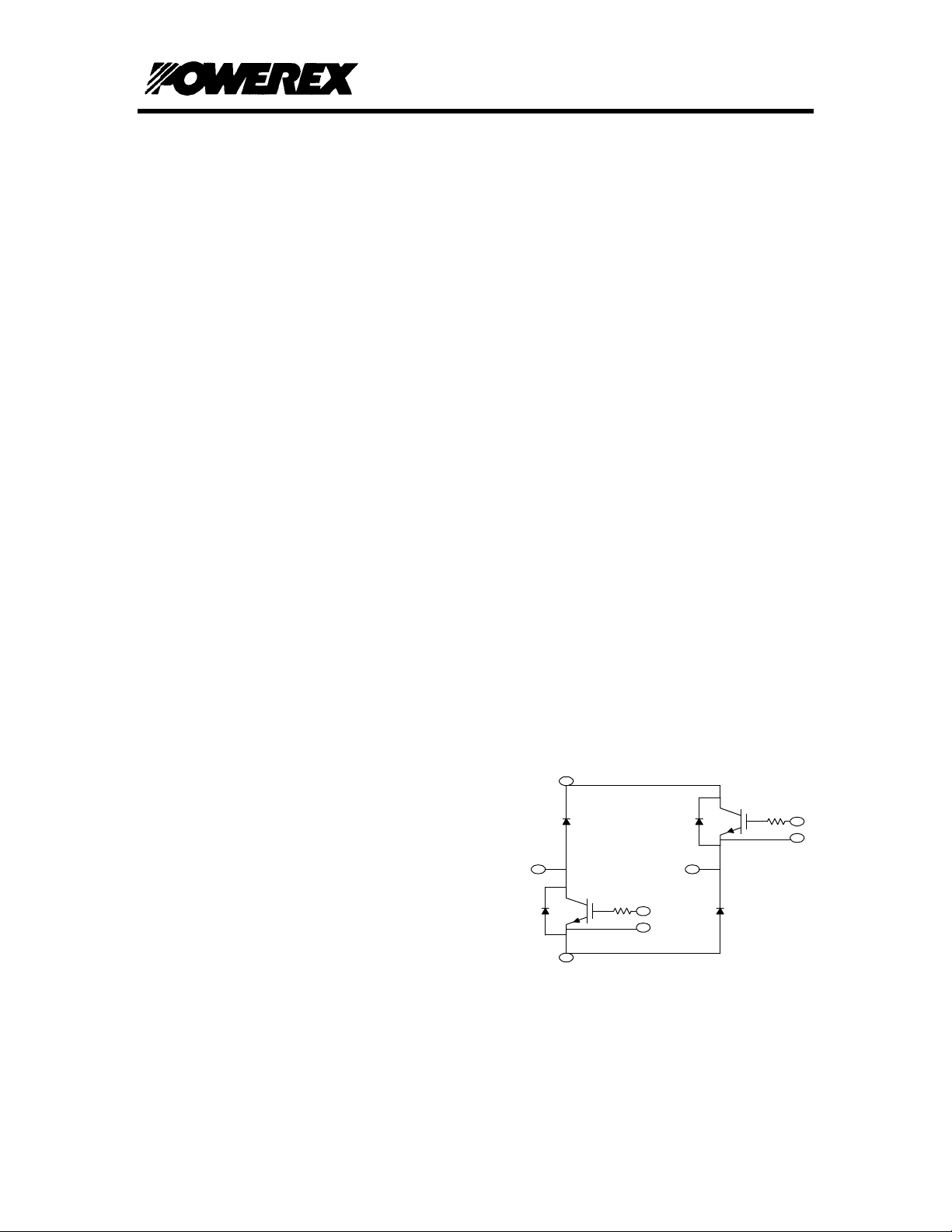
Powerex IGBT Hermetic modules are
designed for use in switching applications.
Each Module consists of two IGBT transistors,
four super fast free wheel diodes in an
asymmetrical half bridge configuration with
each transistor having a reverse connected
super fast recovery free wheel diode. All
components are located in a hermetically
sealed chamber and are electrically isolated
from the heat sinking base plate, offering
simplified system assembly and thermal
management.
Features:
♦ Low Drive Power
♦ Low V
CE(sat)
♦ Discrete Super-Fast Recovery
(70ns) Free-Wheel Diode
♦ Isolated Base plate for Easy Heat
sinking
♦ Fully Hermetic Package
♦ Package Design Capable of Use at
High Altitudes
♦ Package can be modified to adhere
to customer dimensions.
♦ High Capacity Diodes (D1 & D3)
Schematic:
D1 D4
D2 D3
Applications:
♦ AC Motor Control
♦ Motion/Servo Control
♦ Air Craft Applications
Ordering Information:
Page 1 PRELIMINARY 06/06/97
Page 2

QIP0640001
Powerex Inc., 200 Hillis St., Youngwood, PA 15697 (724)925-7272 Asymmetrical Half Bridge IGBT H-Series
Hermetic Module
400 Amperes/600 Volts
Contact Powerex Custom Modules
Page 2 PRELIMINARY 06/06/97
Page 3

QIP0640001
Powerex Inc., 200 Hillis St., Youngwood, PA 15697 (724)925-7272 Asymmetrical Half Bridge IGBT H-Series
Hermetic Module
400 Amperes/600 Volts
Maximum Ratings, Tj=25°°C unless otherwise specified
Ratings Symbol Units
Collector Emitter Voltage V
Gate Emitter Voltage V
Collector Current I
Peak Collector Current I
Diode Forward Current (D2,D4) I
Diode Forward Surge Current (D2,D4) I
Diode Forward Current (D1,D3) I
V Isolation V
CES
GES
C
CM
FM
FM
FM
RMS
600 Volts
±20
Volts
400 Amperes
800* Amperes
400 Amperes
800* Amperes
400 Amperes
2500 Volts
Static Electrical Characteristics, Tj=25°°C unless otherwise specified
Characteristic Symbol Test
Conditions
Collector Cutoff Current I
Gate Leakage Current I
Gate-Emitter Threshold Voltage V
GE(th)
CES
GES
VCE=V
VCE=0V 0.5
IC=40mA,
VCE=10V
Collector-Emitter Saturation Voltage V
CE(sat)
IC=400A,
VGE=15V
V
CE(sat)
IC=400A,
VGE=15V,
T
=150°C
j
Total Gate Charge Q
G
VCC=300V,
IC=400A,
VGS=15V
Diode Forward Voltage (D1,D3) V
FM
IE=400A,
VGS=0V
Diode Forward Voltage (D2,D4) V
FM
IE=200A,
VGS=0V
CES
Min Typ Max Units
1.0 mA
µA
4.5 6.0 7.5 Volts
2.1 2.8 Volts
2.15 Volts
1200 nC
2.0 Volts
2.8 Volts
Dynamic Electrical Characteristics, Tj=25°°C unless otherwise specified
Characteristic Symbol Test
Conditions
Input Capacitance C
Output Capacitance C
Reverse Transfer Capacitance C
Turn on Delay time t
Rise Time t
Turn off delay time t
ies
oes
res
d(on)
r
d(off)
VGE=0V 40 nF
VCE=10V 14 nF
f=1MHz 8 nF
VCC=300V 350 nS
IC=200A 600 nS
V
GE1=VGE2
=15
V
Fall Time t
f
RG=1.6Ω
Diode Reverse Recovery (D1,D3) trr IE=400A 400 nS
Diode reverse Recovery Charge
(D1, D3)
Qrr diE/dt=-
400A/µS
Diode Reverse Recovery (D2, D4) trr IE=200A 110 nS
Diode reverse Recovery Charge
(D2,D4)
Qrr diE/dt=-
400A/µS
Page 3 PRELIMINARY 06/06/97
Min Typ Max Units
350 nS
300 nS
80
1.08
µC
µC
Page 4

QIP0640001
Powerex Inc., 200 Hillis St., Youngwood, PA 15697 (724)925-7272 Asymmetrical Half Bridge IGBT H-Series
Hermetic Module
400 Amperes/600 Volts
Thermal and Mechanical Characteristics, Tj=25°°C unless otherwise specified
Characteristic Symbol Test
ConditionsMin
Thermal Resistance, Junction to Case
Thermal Resistance, Junction to Case
R
θJC
R
θJC
Per IGBT 0.085
Per Diode 0.08
(D1,D3)
Thermal Resistance, Junction to Case
R
θJC
Per Diode 0.18
(D2,D4)
Typ Max Units
°C/W
°C/W
°C/W
Page 4 PRELIMINARY 06/06/97
 Loading...